| (19) |
 |
|
(11) |
EP 0 577 569 B1 |
| (12) |
EUROPEAN PATENT SPECIFICATION |
| (45) |
Mention of the grant of the patent: |
|
24.04.1996 Bulletin 1996/17 |
| (22) |
Date of filing: 25.06.1993 |
|
|
| (54) |
Pliers with movable jaws for gripping bottles or the like for mounting preferably
on an automatic rinsing-sterilizing machine
Zange mit beweglichen Backen zum Greifen von Flaschen oder dergleichen, vorzugsweise
für automatische Spül-/Sterilisiermaschinen
Pince avec mâchoires mobiles pour la prise de bouteilles, préférablement pour le montage
aux machines automatiques de rinçage/stérilisation
|
| (84) |
Designated Contracting States: |
|
AT BE CH DE DK ES FR GB GR IE LI LU MC NL PT SE |
| (30) |
Priority: |
30.06.1992 IT PD920080 U
|
| (43) |
Date of publication of application: |
|
05.01.1994 Bulletin 1994/01 |
| (73) |
Proprietor: OFFICINE AVE S.p.A. |
|
I-30030 Maerne,
Venezia (IT) |
|
| (72) |
Inventor: |
|
- Pusineri, Luca
I-30030 Favaro Veneto (IT)
|
| (74) |
Representative: Sarpi, Maurizio |
|
Studio FERRARIO
Via Collina, 36
I-00187 Roma
I-00187 Roma (IT) |
|
| |
|
| Note: Within nine months from the publication of the mention of the grant of the European
patent, any person may give notice to the European Patent Office of opposition to
the European patent
granted. Notice of opposition shall be filed in a written reasoned statement. It shall
not be deemed to
have been filed until the opposition fee has been paid. (Art. 99(1) European Patent
Convention).
|
[0001] The present patent relates to pliers with movable jaws for gripping bottles, vases
or the like, in glass, ceramic, plastic material or other.
[0002] The subject pliers permit the aforesaid containers to be gripped and moved during
the washing, rinsing or sterilizing operations which are carried out by automatic
or semiautomatic, carrousel or linear machines.
[0003] The prior art provides particular automatic machines for washing, rinsing and/or
sterilizing bottles or the like. Such automatic machines comprise bottle gripping
devices which move the bottles according to a fixed course in which the bottles are,
in general, overturned so that their mouth-pieces are positioned over nozzles which
deliver the treating substances such as water, disinfectants, air, gas or other.
[0004] The known gripping devices are carried out according to a few patterns which comprise,
in general, pliers which consist of a pair of pivoted jaws which grip the bottle-neck
through the action of means which may provoke both the clamping and the opening of
the jaws.
[0005] The opening and closing movements of the jaws may be carried out through pushing
devices which cause the displacement of control parts for the jaws. Such devices are
arranged behind the pivot and may be pins which slide within inclined slots or leverages
or the like, such as in WO-A-9 115 309.
[0006] The pivots or the levers are commonly controlled by cams or other pushing devices
which act on a rod or a slide assembly, during the clamping or release phases.
[0007] The main inconveniences found in the known gripping pliers refer on the one hand
to the difficulty of controlling and adjusting the sliding pivots in the slots of
the jaws since the slots, although shaped, do not permit a perfect clamping of the
bottle if the opening capacity is to be safeguarded, and on the other hand there is
the difficulty of a limited mobility and practicalness of the lever controls which
are difficult to be carried out and do not permit to reach wide openings for large-diameter
containers.
[0008] The present invention removes the aforesaid inconveniences and other consequent ones
since the subject pliers are provided with new moving elements which offer a double
possibility. In fact, on the one hand such moving elements permit the pliers to be
opened till reaching a large width so that it is possible for the pliers to grip also
bottles or vases having long diameters. On the other hand such moving elements permit
an effective returning action of the jaws so as to obtain a stronger grip than any
other pliers without affecting the opening capacity.
[0009] Within the sphere of the above-described general object, the pliers in question are
provided with jaws which are moved symmetrically by opening and closing members acting
on the extensions of the jaws, such extensions being cam-shaped and arranged behind
the pins. The form and direction of the cam-shaped parts may be varied according to
whatever angle based on the wished opening of the jaws.
[0010] The peculiarity of the pliers according to the present invention is that the direction
of the inner sides of the cam-shaped extensions can be nearly parallel to the thrust
line, the closing thrust being interposed between such inner sides, and therefore
the returning action of the jaws may reach a very high force which is necessary for
an effective grip of the bottles.
[0011] In fact, the invention refers to pliers with movable jaws for gripping bottles or
the like for mounting preferably on automatic, carrousel or linear, rinsing or sterilizing
machines, characterized by the fact that both jaws are pivoted upon a jaws supporting
assembly and show an extension which is arranged behind the pin, such extension being
cam-shaped with curvilinear or linear sloping parts with variable angles; the cam-shaped
extension of each jaw is intercepted by pairs of pins which are arranged two by two
on a thrust and/or draw sliding block which is arranged against a preloaded spring
which is placed on a shaft which is secured to the sliding block and is placed between
the jaws and the jaws supporting assembly; the thrust and draw action is accomplished
by the pins of the sliding block on the cam-shaped extensions of the jaws and provokes
the opening and closing of the jaws through the intervention of usual thrust means
acting on the sliding block itself; the cam-shaped extensions of the jaws may show
whatever angle according to the wished opening capacity and clamping force.
[0012] The invention will be comprised better from the following specification with reference
to the accompanying drawings which represent a preferred embodyment wherein:
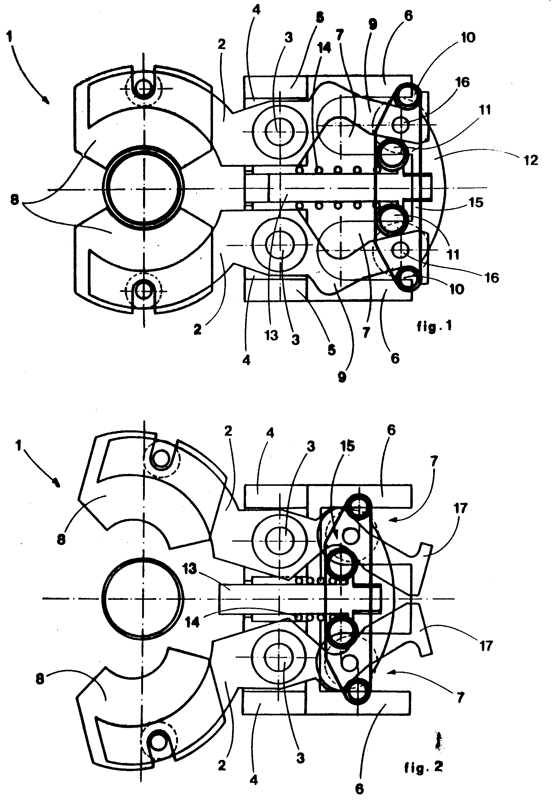
Fig. 1 shows a schematic plan view of the pliers according to the present invention
as a whole and in close position;
Fig. 2 shows a corresponding schematic view but in open position;
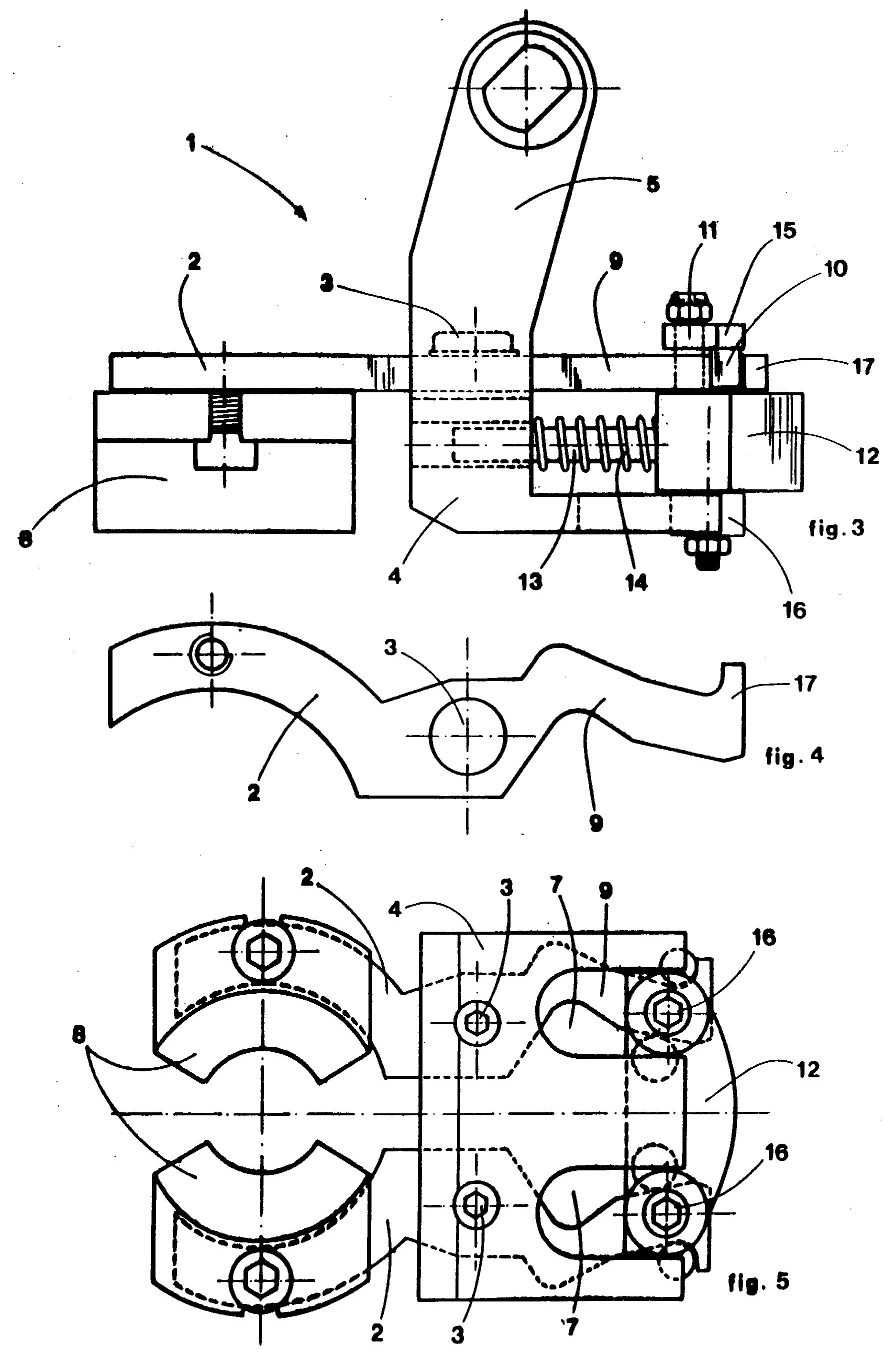
Fig. 3 shows a schematic side view of the pliers in question;
Fig. 4 shows a schematic view of a detail of a jaw; and
Fig. 5 shows a schematic view of the pliers in which the jaws supporting part is in
evidence.
[0013] With reference to the accompanying drawings, in general number 1 denotes pliers for
gripping bottles or the like for mounting preferably on an automatic, carrousel or
linear, rinsing-sterilizing machine.
[0014] Essentially, such pliers consist of two jaws 2 which may be moved symmetrically on
pins 3. The jaws 2 are symmetrical and each other's mirror image.
[0015] The pins 3 of the jaws are secured to an L-shaped bracket 4 which comprises arms
5. The arms 5 are used to mount a jaws supporting assembly on the fixed part of the
machine. The bracket 4 is also provided with appendixes 6 which form parallel cavities
7 the function of which will be described below.
[0016] The fore ends of the jaws get out from the bracket 4 and are shaped like semicircles.
The fore ends of the jaws are provided with conventional pads 8 for gripping the bottle-necks.
[0017] The rear parts of the jaws, such parts being arranged behind the pins 3, form cam-shaped
extensions 9 which are intercepted by the members which control the opening and clamping
of the jaws.
[0018] The cam-shaped extensions 9 are in fact included between pairs of pins 10 and 11
which are fixed to a central sliding block 12 which may slide between the extensions
9 and the appendixes 6 of the bracket 4.
[0019] The sliding block 12 slides axially along a hypothetical center line between both
jaws on a shaft 13 and is kept in a pushing position towards the outside of the bracket
4 by means of a preloaded spring which is arranged on the shaft 13 itself.
[0020] As already said, the pins 10 and 11 are fixed on the sliding block 12.
[0021] The cam-shaped extensions 9 are intercepted by the pins laterally and are also kept
by an upper closing plate 15.
[0022] Moreover, the sliding block 12 is guided in its thrust and draw movements by guide
rolls 16 which slide along the previously mentioned parallel cavities 7 of the bracket
4.
[0023] The cam-shaped extensions 9 are so shaped that during the advancing motion of the
sliding block the outer pins 10 push on the outer side of both cam-shaped extensions
in order to provoke the opening of the jaws whereas in the phase of return of the
sliding block the inner pins 11 push on the inner side of both cam-shaped extensions
in order to provoke the closing of the jaws.
[0024] As concerns the opening capacity of the jaws and the clamp force of the jaws on the
bottleneck, the shape of the extensions is very important since it is possible to
reach more or less wide openings of the jaws by varying the angle of the outer side
of the cam extensions while the shape of the inner side of the cam extensions determines
the force with which the jaws grip the bottleneck.
[0025] The preferred shape of the jaws 2 with their respective cam extensions 9 is shown
in Fig. 4 where it can be seen that the outer side of the cam-shaped extension 9 has
a slightly curved profile with the angle with respect to the slide middle axis of
the sliding block 12 increasing towards the gripping end of the jaw whereas the inner
side has a discontinue profile with a very angled initial sector close to the gripping
end and a final sector which is nearly parallel to the slide middle axis of the sliding
block, when the jaws are in their gripping position.
[0026] The aforesaid measures permit that the first sector of the inner side of the cam-shaped
extension provokes the clamping of the jaw when the inner pins 11 are retracted while
the second sector, which is less sloping, facilitates and completes the clamping of
the bottleneck and prevents the jaw from partially releasing the bottleneck during
the displacements of the bottles, such displacements being often rapid.
[0027] Accordingly, it is evident that a change of the angle and direction of the cam-shaped
extension 9 involves also a change in the movements which the jaw makes during the
displacements of the pins 10 and 11 together with the sliding block on which such
pins are mounted.
[0028] Finally, the end part of bothcam-shaped extensions is provided with a stop tooth
17 which determines the maximum retracting point for the outer pins 10 and the whole
sliding part of the sliding block 12.
[0029] The onward movement of the sliding block for provoking the opening of the jaws is
caused by a known thrust device such as a cam or other while the backward movement
of the sliding block is provoked by a preloaded spring 14 which is arranged on the
slide shaft 13 of the sliding block itself.
[0030] The gripping pliers according to the present invention have been described and represented
according to a preferred solution but variants may be provided within the range of
protection of the claims.
1. Pliers with movable jaws for gripping bottles or the like for mounting preferably
on automatic, carrousel or linear, rinsing-sterilizing machines, wherein both jaws
(2), which are pivoted around pins (3) on a supporting bracket (4), are provided with
an extension (9) which is arranged behind a pin (3), and wherein a thrust and/or draw
sliding block (12) is provided, which can be displaced against the force of a preloaded
spring (14) to provoke opening of the jaws, characterized in that each extension (9)
is shaped essentially like a cam with inclined, curved or linear parts, the angle
being variable; the cam-shaped extension (9) of each jaw (2) is intercepted by a pair
of pins (10, 11), of which one pin (10) is arranged on the outer side of the extension
(9) and the other pin (11) on the inner side of the extension (9); the pairs of pins
(10, 11) are coupled two by two on said sliding block (12) and said spring (14) is
provided on a slide shaft (13) which is fixed to the sliding block (12).
2. Pliers as claimed in claim 1, characterized in that the sliding block (12) is arranged
between the rear extensions (9) of the jaws (2) and the supporting bracket (4) and
is guided in its thrust and draw motions by means of rolls (16) or the like which
can slide along parallel cavities (7) provided in the supporting bracket (4).
3. Pliers as claimed in the foregoing claims, characterized in that the thrust and draw
action carried out by the pins (10, 11) of the sliding block (12) on the cam-shaped
extensions (9) of the jaws (2) causes the opening and closing, respectively, of the
jaws (2) through the intervention of thrust means acting on the sliding block (12).
4. Pliers as claimed in the foregoing claims, characterized in that the cam-shaped extensions
(9) of the jaws (2) may show any angles according to the wished opening capacity and
to the wished clamp force.
5. Pliers as claimed in the foregoing claims, characterized in that the shape of the
cam-extensions (9) is such that the outer pins (10) push on the outer sides of the
cam-shaped extensions during the advancing motion of the sliding block (12) so as
to determine the opening of the jaws (2) while the inner pins (11) push on the inner
sides of the cam-shaped extensions (9) during the phase of return of the sliding block
(12) so as to determine the clamp of the jaws (2).
6. Pliers as claimed in the foregoing claims, characterized in that the preferred shape
of the cam-shaped extensions (9) is such that the outer sides of the extensions (9)
have a slightly curved profile with the angle with respect to the slide middle axis
of the sliding block (12) increasing towards the gripping parts of the jaws while
the inner sides have a discontinue profile, the initial sector, close to the gripping
parts of the jaws, being very angled and the final sector being nearly parallel to
said slide middle axis, when the jaws are in their gripping position.
7. Pliers as claimed in the foregoing claims, characterized by the fact that the final
part of the cam-shaped extensions (9) is provided with a stop tooth (17) which determines
the maximum retracting point for the outer pins (10) and for the whole sliding part
of the sliding block (12).
1. Zange mit beweglichen Backen zum Greifen von Flaschen oder dergleichen, zum Anbringen
vorzugsweise an automatische, kreiförmige oder lineare Spül-Sterilisations-Maschinen,
wobei die beiden Backen (2), die um Stifte (3) an einem Halter (4) angelenkt sind,
mit einem Ansatz (9) versehen sind, der hinter einem Stift (3) angeordnet ist, und
wobei ein Drück- und/oder Zug-Gleitblock (12) versehen ist, der gegen die Kraft einer
vorgespannten Feder (14) verschiebbar ist, um die Öffnung der Backen hervorzurufen,
dadurch gekennzeichnet, daß jeder Ansatz (9) im wesentlichen wie ein Nockenkörper
mit geneigten, gebogenen oder linearen Abschnitten gestaltet ist, wobei der Winkel
variabel sein kann, daß an dem nockenförmigen Ansatz (9) eines jeden Backens (2) ein
Paar von Stiften (10, 11) angreift, wobei der eine Stift (10) auf der Außenseite des
Ansatzes (9) und der andere Stift (11) auf der Innenseite des Ansatzes (9) angeordnet
ist, daß die Stifte (10, 11) paarweise auf dem besagten Drück- und/oder Zug-Gleitblock
(12) gekoppelt sind, und daß die besagte Feder (14) auf einem Gleitschaft (13) vorgesehen
ist, der an den Gleitblock (12) befestigt ist.
2. Zange gemäß Anspruch 1, dadurch gekennzeichnet, daß der Gleitblock (12) zwischen der
rückseitigen Ansätzen (9) der Backen (2) und dem Halter (4) angeordnet ist und bei
seinen Drück- und Ziehbewegungen durch Rollen (16) oder dergleichen geführt ist, die
entlang paralleler Ausnehmungen (7) gleiten können, die in dem Halter (4) ausgebildet
sind.
3. Zange gemäß den vorausgehenden Ansprüchen, dadurch gekennzeichnet, daß die Drück-
und Zugaktion, die von der Stiften (10, 11) des Gleitblockes (12) auf die nockenförmigen
Ansätze (9) der Backen (2) ausgeübt wird, durch das Einwirken von den Gleitblock (12)
beaufschlagenden Beaufschlagungsmitteln das jeweilige Öffnen und Schließen der Backen
(2) verursacht.
4. Zange gemäß den vorausgehenden Ansprüchen, dadurch gekennzeichnet, daß die nockenähnlich
geformten Ansätze (9) der Backen (2) entsprechend dem gewünschten Öffnungsvermögen
und der gewünschten Klemmkraft jegliche Winkel aufweisen können.
5. Zange gemäß den vorausgehenden Ansprüchen, dadurch gekennzeichnet, daß die Nocken-Ansätze
(9) eine derartige Gastalt haben, daß die äußeren Stifte (10) während der Vorwärtsbewegung
des Gleitblockes (12) auf die Außenseiten der nockenartig geformten Ansätze drücken,
um das Öffnen der Backen (2) zu bewirken, wohingegen die inneren Stifte (11) während
der Rückkehrphase des Gleitblockes (12) auf die Innenseiten der nockenartig geformten
Ansätze (9) drücken, um das Klemmen der Backen (2) zu bewirken.
6. Zange gemäß den vorausgehenden Ansprüchen, dadurch gekennzeichnet, daß die bevorzugte
Gestalt der nockenförmig gestalteten Ansätze (9) derart ist, daß die Außenseiten der
Ansätzen ein leicht kurvonförmiges Profil mit dem ansteigenden Winkel in bezug auf
die Gleitmittelachse des Gleitblockes (12) in Richtung zu den Greifabschnitten der
Backen aufweisen, während die Innenseiten ein diskontinuierliches Profil haben, wobei
der Anfangsabschnitt in der Nähe der Greifabschnitten der Backen stark angewinkelt
und der Endabschnitt nahezu parallel zur besagten Gleitmittelachse ist, wann die Backen
in ihren Greifposition sind.
7. Zange gemäß den vorausgehenden Ansprüchen, dadurch gekennzeichnet, daß der Endabschnitt
der nockenförmigen Ansätze (9) mit einem Anschlagzahn (17) versehen ist, der den maximalen
Rückzugspunkt für die äußeren Stifte (10) und für den gesamten Gleitteil des Gleitblockes
(12) bestimmt.
1. Pince pourvue de mâchoires mobiles adaptée pour saisir des bouteilles su objets de
ce genre et pour être montée, de préférance sur des machines automatiques de rinçage-stérilisation,
costituées sous forme circulaire ou linéaire, ce pince ayant les deux mâchoires (2)
qui sont montés autour aux pivots (3) sur une console de support (4), ces machoirs
sont pourvues d'un prolongement (9) disposé en arrière d'un pivot (3), et dans lequel
est pourvu un bloc coulissant de poussée et/ou de traction (12) et qui peut être déplacé
contre la force d'un ressort soumis à une précontrainte (14) pour provoquer l'ouverture
des machoirs, caracterisée par le fait que chaque prolongement (9) est conformé en
forme de came comportant des parties inclinées, courbes ou droites, sous un angle
variable; le prolongement en forme de came (9) de chaque machoir (2) est encadré par
deux goujons (10, 11), un goujon (10) étant situé extérieurement à ce prolongement
(9) et l'autre goujon (11) étant situé intérieurement à ce prolongement (9); les couples
de goujons (10, 11) sont couplés deux par deux sur le bloc coulissant (12), et dite
ressort (14) étant engagé sur un arbre de coulissement (13) qui est fixé sur le bloc
coulissant (12).
2. Pince selon la revendication 1, caracterisée par le fait que le bloc coulissant (12)
est située entre les prolongements arrière (9) des mâchoires (2) et la console de
support (4) et est guidé dans ses mouvements en poussé et en traction au moyen de
galets (16) ou éléments semblables qui peuvent glisser le long d'évidements parallèles
(7) qui sont prévus dans la console de support (4).
3. Pince selon l'une ou l'autre des revendications 1 ou 2, caracterisée par le fait que
l'action de poussée et de traction exercée par les goujons (10, 11) du bloc coulissant
(12) sur le prolongement (9) en forme de came des mâchoires (2) êntraine, respectivement,
l'ouverture et la fermeture de ces mâchoires (2) en faisant intervenir des moyens
de poussée qui agissent sur le bloc coulissant (12).
4. Pince selon l'une quelconque des revendications 1 à 3, caracterisée par le fait que
les prolongements (9) en forme de came des mâchoires (2) peuvent comporter toutes
sortes d'angles selon la capacité d'ouverture et de la force de serrage que l'on souhaite
obtenir.
5. Pince selon l'une quelconque des revendications 1 à 4, caracterisée par le fait que
la forme des prolongements en forme de came (9) est adaptée de maniere que les goujons
externes (10) poussent sur les côtés extérieurs des prolongements en forme de came
pendant le mouvement d'avancement du bloc coulissant (12) de manier à déterminer l'ouverture
des mâchoires (2) tandis que les goujons internes (11) poussent sur les côtes intérieurs
des prolongements (9) en forme de came pendant le mouvement de retour du bloc coulissant
(12) de manière à déterminer le serrage des mâchoires (2).
6. Pince selon l'une quelconque des revendications 1 à 5, caracterisée par le fait que
la forme préférée des prolongements (9) en forme de came est telle que les côtés extérieurs
de ces prolongements (9) ont un profil légèrement incurvé avec l'angle en relation
à l'axe central de coulissement du bloc coulissant (12) augmentant vers les parties
de préhension des mâchoires tandis que les côtés intérieurs présentent un profil brisé,
le secteur initial, près de parties de préhension des machoirs, étant très angulaire
et le secteur final étant pratiquement parallèle à l'axe central de coulissement,
quand les mâchoires sont dans leur position de préhension.
7. Pince selon l'une quelconque des revendications 1 à 6, caracterisée par le fait que
le secteur final des prolongements (9) en forme de came est pourvu d'un dent d'arrêt
(17) qui détermine le point de recul maximal pour les goujons externes (10) et pour
toute la partie coulissante du bloc coulissant (12).