| (19) |
 |
|
(11) |
EP 0 609 252 B1 |
| (12) |
EUROPEAN PATENT SPECIFICATION |
| (45) |
Mention of the grant of the patent: |
|
11.12.1996 Bulletin 1996/50 |
| (22) |
Date of filing: 29.09.1992 |
|
| (86) |
International application number: |
|
PCT/GB9201/779 |
| (87) |
International publication number: |
|
WO 9308/327 (29.04.1993 Gazette 1993/11) |
|
| (54) |
METHOD FOR MAKING SHEET MATERIALS AND SECURITY PAPER
VERFAHREN ZUR HERSTELLUNG BAHNFORMIGES MATERIAL UND SICHERHEITSPAPIER
PROCEDE DE FABRICATION DE MATERIAUX EN FEUILLE ET DE PAPIER FIDUCIAIRE
|
| (84) |
Designated Contracting States: |
|
AT BE CH DE DK ES FR GB GR IE IT LI LU MC NL SE |
| (30) |
Priority: |
25.10.1991 GB 9122694
|
| (43) |
Date of publication of application: |
|
10.08.1994 Bulletin 1994/32 |
| (73) |
Proprietor: PORTALS LIMITED |
|
London, WC2N 4DE (GB) |
|
| (72) |
Inventor: |
|
- KNIGHT, Malcom Robert Murray
Basingstoke,
Hampshire RG25 2BP (GB)
|
| (74) |
Representative: Hardisty, David Robert et al |
|
BOULT, WADE & TENNANT
27 Furnival Street
London EC4A IPQ
London EC4A IPQ (GB) |
| (56) |
References cited: :
EP-A- 0 059 056
US-A- 4 534 398
|
GB-A- 1 604 463
|
|
| |
|
|
|
|
| |
|
| Note: Within nine months from the publication of the mention of the grant of the European
patent, any person may give notice to the European Patent Office of opposition to
the European patent
granted. Notice of opposition shall be filed in a written reasoned statement. It shall
not be deemed to
have been filed until the opposition fee has been paid. (Art. 99(1) European Patent
Convention).
|
[0001] This invention relates to a method of making sheet materials and security paper having
partially embedded therein an elongate security element which is partially disposed
within the thickness of the sheet and exposed at spaced locations.
[0002] Bank notes and other security documents including cheques, warrants, identification
cards, credit cards or guarantee cards formed from security paper or materials incorporating
such partially exposed security strips or threads have been in circulation for a number
of years and are now widely used in many countries. The security strip or thread in
such documents is exposed in a controlled manner on one side of the paper from which
the document is formed. Such exposed regions are commonly referred to as "windows"
in the paper and the exposed regions of the thread are readily visible in reflected
light at these windows.
[0003] British patent specification GB-A-741,675 discloses a Fourdrinier-type papermaking
machine which is used to produce corrugated paper having some raised and some recessed
portions. British patent specification GB-A-1,447,933 teaches a further adapted Fourdrinier-type
papermaking machine utilising an endless foraminous belt supporting embossed portions
for producing a watermark which has areas of different thicknesses. European patent
specification EP-A-0,367,520 discloses another papermaking machine of the Fourdrinier-type
construction which uses differential compaction asserted by a dandy roll carrying
embossed watermark designs to create watermarks in the paper produced thereon. Although
these prior art specifications demonstrate ways of creating paper with variable thicknesses
on Fourdrinier-type machines, none of them disclose apparatus or methods for producing
windowed security paper incorporating a security element.
[0004] European patent specification EP-A-0,166,189 discloses a technique for forming paper
by simultaneous drainage through a rotating cylinder and an outer wire but does not
disclose a technique for forming windowed paper.
[0005] British patent specifications GB-A-1,552,853 and GB-A-1,604,463 disclose windowed
security paper in which a security device is embedded within the paper. The windows
are created by laser burning, mechanical cutting or abrasive means, which method involves
multi-step processes, which are costly and time-consuming.
[0006] European patent specification EP-A- 0059056 also relates to a method of making such
windowed security paper. In the specification a method is proposed for depositing
fibres on the mesh cylinder of a cylinder mould papermaking machine, which rotates
in a vat of papermaking fibres. An elongate security thread is fed into contact with
the cylinder which has raised portions thereon so that the thread overlies the raised
portions as fibres begin to deposit on the cylinder. Fibres are progressively deposited
on the cylinder, over the thread and also below the level of the thread except where
it is in contact with the raised portions. A disadvantage of this prior technique
is that for the range of substances (78-90 grams per square metre) and manufacturing
speeds (20-80 m/min) commonly used for banknote paper, the width of security threads
which may be incorporated into paper is restricted to less than 3mm. Above this width,
there is insufficient fibre deposition behind the thread since the deposition and
thus formation of paper takes place through the cylinder on which the thread is laid
and this deposition cannot efficiently occur across the full width of a wide security
thread.
[0007] The resulting paper produced by this method has the thread exposed at one surface
of the paper where the thread contacted a raised portion and is continuously covered
on the other side of the paper.
[0008] EP-A-0,229,645 additionally discloses a method of combining two wet webs of paper
with regions of few or no fibres in one or more of the layers of paper, and inserting
a security element into the paper such that the security element embedded beneath
the layer or layers is exposed at windowed portions in the finished sheet. However,
this requires a very high degree of lateral registration between the security element
insertion apparatus and the pre-formed regions containing few or no fibres; such registration
is extremely difficult to achieve in practice.
[0009] United States of America patent specification US-A-4,534,398 relates to method of
making security paper incorporating a number of discrete security elements which are
pressed into a web of wet based paper fibres formed on a Fourdrinier-type moving wire.
The discrete security elements are mounted on a carrier paper which, on contacting
the wet base fibres, draw some fibres and water up within the carrier paper to form
a composite paper. This specification does not disclose any means for exposing a continuous
security element in windows on one side of the sheet.
[0010] It is an object of the invention to overcome the aforementioned disadvantages and
to achieve a method of making windowed sheet materials and security paper incorporating
an elongate security element using modifications of paper making apparatus, such as
a Fourdrinier machine.
[0011] A method of making a sheet of material generally incorporating a continuous elongate
security element which is at least substantially exposed at windows in one surface
of the sheet at a plurality of spaced locations, which method comprises the steps
of depositing aqueous fibrous stock comprising a mixture of water and fibres onto
a support surface, and introducing the security element under tension into deposited
fibrous stock, characterised by bringing the security element into contact with a
rotatable embedment means, which embedment means comprises a plurality of spaced apart
raised portions having recesses therebetween, the recesses being defined by the sides
of adjacent raised portions and a base, the security element being brought to lie
across adjacent raised portions overlying the recesses therebetween, and rotating
the embedment means to effect the introduction of the security element into the fibrous
stock such that fibres are caused to move into said recesses and in particular between
the security element and the base of the recesses to form bridges at a plurality of
spaced locations covering the security element between adjacent windows, further characterised
in that the support surface is moved in a substantially linear direction and in that
the tension applied to the elongate security element maintains contact of the security
element with the raised portions of the embedment means to prevent said fibres substantially
from penetrating between the raised portions and the overlying security element.
[0012] Inter alia, the present technique permits manufacture of banknote paper containing
wide windowed security threads at higher speeds than is possible using prior techniques.
[0013] The preferred embodiment of the invention comprises a method of making a sheet of
material generally incorporating a continuous security element which is at least substantially
exposed at one surface of the sheet at a plurality of spaced locations, which method
comprises the step of depositing fibres onto a continuous moving foraminous support,
supplying a continuous security element to overlie a rotatable cylinder, which cylinder
comprises a plurality of spaced apart raised portions having recesses therebetween,
rotating the cylinder in contact with the deposited fibres creating pressure between
said cylinder and the support wire thereby forcing the security element into the fibres,
such that some fibres move into said recesses between the security element and the
cylinder so that the security element is covered by fibres, and substantially preventing
fibres from penetrating between the raised portion and the overlying security element.
[0014] A papermaking machine for making sheets of paper generally incorporating an elongate
security element which is at least substantially exposed at windows in one surface
of the sheet at a plurality of spaced locations, comprising a support surface on to
which is deposited aqueous fibrous stock comprising a mixture of water and fibres
and means for introducing the security element under tension into deposited fibrous
stock, characterised by the provision of a rotatable embedment means, which embedment
means comprises a plurality of spaced apart raised portions having recesses therebetween,
the recesses being defined by the sides of adjacent raised portions and a base, means
for bringing the security element to lie across adjacent raised portions of the embedment
means overlying the recesses therebetween, wherein rotating the embedment means effects
the introduction of the security element into the fibrous stock such that fibres are
caused to move into said recesses and in particular between the security element and
the base of the recesses to form bridges at a plurality of spaced locations covering
the security element between adjacent windows, further characterised by the provision
of means to move the support surface in a substantially linear direction and to apply
tension to the elongate security element such that it maintains contact of the security
element with the raised portions of the embedment means to prevent said fibres substantially
from penetrating between the raised portions and the overlying security element.
[0015] The invention will now be described, by way of example, with reference to the accompanying
drawings in which:-
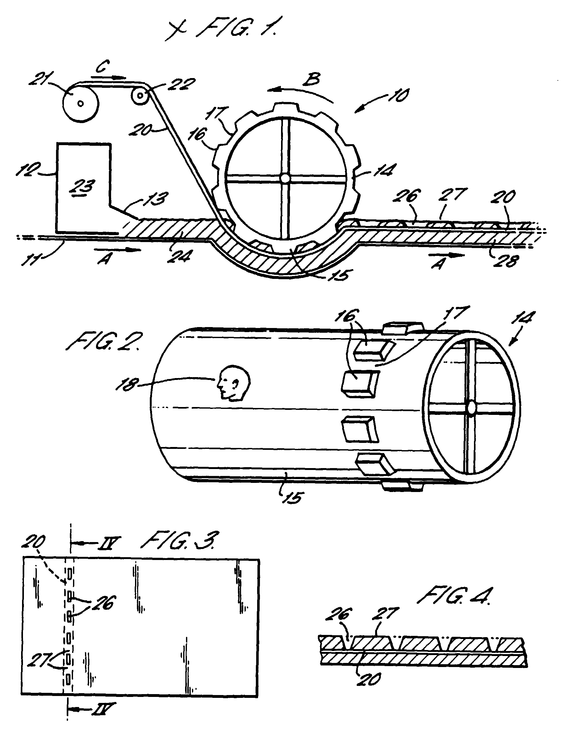
FIG. 1 is a schematic section (not to scale) through a modified Fourdrinier paper
machine in normal operation inserting a security thread into the paper being made;
FIG. 2 shows an enlarged perspective view of a cylinder used in the machine of Fig.
1;
FIG. 3 is a plan view of a finished bank note incorporating a security device made
from paper produced by the machine of Fig. 1; and
FIG. 4 shows an enlarged portion of the cross section through the bank note of Fig.
3 on the line IV-IV of Fig. 3.
[0016] Referring to Figs. 1 and 2 there is shown a modified Fourdrinier-type paper making
machine 10. The machine 10 comprises an endless foraminous support wire 11 which is
supported and driven in the direction of arrows A by an appropriate arrangement of
rollers or other support and driving means (not shown). A head box 12 containing aqueous
fibre stock 23 is located adjacent the wire 11 and has a mouth or slice 13 located
directed above the wire 11 to maintain a continuous relatively level supply of the
aqueous fibre stock to be fed to the moving wire 11.
[0017] A cylinder 14 is positioned above the wire 11 and is driven by appropriate means
(not shown) to rotate in the direction of arrow B. The cylinder 14 is covered with
a porous wire mesh 15 which is embossed with portions 16, which are raised with respect
to the surrounding level of wire mesh 15. The recesses 17 between the raised portions
16 may or may not actually be recessed with respect to the surrounding wire mesh 15,
according to the required surface finish of the end product. The raised portions 16
and recesses 17 extend for typically, but not exclusively, 6-30mm in a direction parallel
to the axis of the cylinder 14 and for 1-15mm in the circumferential direction. The
actual sizes of the raised portions 16 and recesses 17 are determined by the required
size of windows in the resulting paper. optionally, the wire mesh 15 may also include
an additional embossing 18 e.g. in the form of a human portrait, which will create
a type of watermark in the final paper required.
[0018] Where the wire 11 passes beneath cylinder 14, the wire 11 follows an arcuate path,
to take account of the curvature of the cylinder 14.
[0019] The continuous flexible security element in the form of a strip or thread 20 to be
fed into the paper, is generally of uniform construction and thickness. Such a thread
20 is typically 12 micron polyester vacuum metallised with aluminium on one or both
sides and coated on one of those sides with a protective and/or adhesive material.
Obviously other designs or compositions may be used according to the desired end effect.
The preferred security strip or thread is typically, but not exclusively, 2 to 10mm
wide, or more preferably 2 to 5mm, and even more preferably 4mm. The actual size used
will depend on the required effect. The security thread may be in excess of 10mm in
certain cases. The thread 20 is fed from a bobbin 21 over a guide mechanism 22 in
the direction of arrow C. The guide mechanism 22 is positioned such that the thread
20 makes contact with the raised portions 16 of wire mesh 15, above the level of the
paper being formed and maintains tension of the thread.
[0020] In operation, aqueous fibrous stock is fed from a supply 23 via the mouth 13 of head
box 12 to form a generally even deposited layer of fibrous stock 24. Water from the
layer of deposited stock 24 drains through the holes in the wire 11 thus leaving fibres
deposited on the wire 11 starting the formation of the sheet of paper. As the wire
11 passes beneath the rotating cylinder 14, the raised portions 16 of the cylinder
14 move the overlying thread 20, which is in contact therewith, down into the layer
of fibres 24. Some of the fibres of the draining paper layer 24 are thereby displaced
and forced by the pressure between the cylinder 14 and foraminous wire 11 into the
recesses 17 of the cylinder between the security thread 20 and the wire mesh 15. The
fibres, however, are not able to penetrate between the thread 20 and the wire mesh
15 at the raised portions 16.
[0021] Drainage of water from the paper layer 24 continues to take place through the holes
of the supporting wire 11. Optionally, further drainage takes place through the wire
mesh 15 covering the cylinder 14, although such drainage may need to be assisted by
a vacuum extraction system in the region where the cylinder 14 is in contact with
the layer 24.
[0022] As it is necessary to prevent fibres occurring between the raised portions 16 and
the thread 20, the initial point of contact of the thread 20 on the raised portions
16 must take place before the raised portions 16 come into contact with the layer
of fibres 24. Correct tensioning of the thread 20 will ensure that this contact is
maintained and prevents the unwanted penetration of fibres accordingly.
[0023] As the partially formed paper on the wire 11 leaves the cylinder 14, the security
thread 20 is just exposed on one side at regions or windows 26, which were formerly
in contact with the raised portions 16, but is covered with fibres at intervening
regions 27. The other side of the thread 20 is fully covered with fibres. Further
drainage and consolidation of the sheet of paper continues to take place and conventional
press and drying apparatus complete the paper manufacturing process. Following this,
the resulting paper is reeled into webs for subsequent finishing and printing operations.
The finished paper can be processed to form a bank note, such as the one shown in
Fig. 3, which has regions 26 on one side where the security thread 20 is exposed inbetween
regions 27 where it is covered. On the other side of the bank notes (not shown) the
thread 20 is fully enclosed in fibres.
[0024] Using the technique disclosed in this specification, it is possible to produce banknote
paper containing a wider security thread (3mm or more) than is possible using the
technique of EP-A-0059056. Firstly, the pressure generated between the rotating cylinder
14 and foraminous wire 11 is effective in forcing fibre between a wide security thread
20 and the recesses 17 thus ensuring full fibre coverage of regions 27 between the
windows 26. Secondly, since the paper is essentially formed by drainage through the
foraminous wire 11 before and during embedment of the security thread, there is full
fibre coverage of the thread on the reverse side of the sheet at 28.
[0025] Other modifications may be made to the machine which are as follows.
[0026] In one alternative embodiment, the raised portions 16 on the cylinder 14 comprise
a water impermeable substance, such as flexible rubber, bonded onto the wire mesh
15. Alternatively the raised portions 16 may be partially pervious and partially impervious.
[0027] In another alternative embodiment, the head box 12 may be placed very close to the
nip between the rotating cylinder 14 and the foraminous wire 11 to inject the aqueous
stock 23 directly into the nip. Also, the support wire 11, the rotating cylinder 14,
or both may be subjected to lateral shaking parallel to the axis of the cylinder 14,
to assist the formation of the paper in a manner similar to that of a conventional
Fourdrinier machine. Where such shaking is adopted, it is preferable to shake both
the wire 11 and the cylinder 14 together in phase. Typically, the guide mechanism
22 for the security strip 20 is subjected to controlled lateral oscillation with respect
to the wire 11 and rotating cylinder 14 in order to oscillate the position of the
security strip in the finished paper. This is a conventional procedure, adopted to
minimise distortion of the paper web or stack of sheets by the inclusion of the security
thread 20 which typically increases the overall thickness of the paper in the region
of the thread.
[0028] Preferably, the cylinder 14 extends to the full width of the paper machine and wire
11. The same cylinder may have multiple sets of raised portions 16 according to the
number of security threads 20 required across the width of the paper web.
[0029] Alternatively, the cylinder 14 may be substantially narrower in the axial direction
and could be essentially the same width as the raised portions 16. In this embodiment,
multiple cylinders 14 may be used across the width of the machine, each containing
one series of raised portions 16.
[0030] In yet another variant, two or more cylinders 14 are placed across the width of the
machine, each providing several series of raised portions 16.
[0031] The fibres used to manufacture paper according to this technique may be natural (e.g.
cotton, linen, wood) or synthetic (e.g. polyester, viscose, nylon, polyvinyl alcohol)
or a mixture of natural/synthetic fibres.
1. A method of making a sheet of material generally incorporating a continuous elongate
security element (20) which is at least substantially exposed at windows (26) in one
surface of the sheet at a plurality of spaced locations, which method comprises the
steps of depositing aqueous fibrous stock (23) comprising a mixture of water and fibres
onto a support surface (11), and introducing the security element (20) under tension
into deposited fibrous stock (23), characterised by bringing the security element
(20) into contact with a rotatable embedment means (14), which embedment means (14)
comprises a plurality of spaced apart raised portions (16) having recesses (17) therebetween,
the recesses (17) being defined by the sides of adjacent raised portions (16) and
a base, the security element (20) being brought to lie across adjacent raised portions
(16) overlying the recesses (17) therebetween, and rotating the embedment means (14)
to effect the introduction of the security element (20) into the fibrous stock (23)
such that fibres are caused to move into said recesses (17) and in particular between
the security element (20) and the base of the recesses (17) to form bridges at a plurality
of spaced locations covering the security element (20) between adjacent windows (26),
further characterised in that the support surface (11) is moved in a substantially
linear direction and in that the tension applied to the elongate security element
(20) maintains contact of the security element (20) with the raised portions (16)
of the embedment means (14) to prevent said fibres substantially from penetrating
between the raised portions (16) and the overlying security element (20).
2. A method as claimed in claim 1 further comprising the step of bringing the elongate
security element (20) into contact with the said raised portions (16) before it comes
into contact with the fibrous stock (23).
3. A method as claimed in any one of the preceding claims in which the embedment means
(14) comprises a rotating wire mesh cylinder (15) bearing the spaced apart raised
portions (16) raised relative to adjacent areas of the cylinder (15) surface.
4. A method as claimed in any one of the preceding claims in which the fibrous stock
(23) is continuously deposited on the support surface (11), which is moved in a continuous
path beneath the embedment means (14), to form a sheet which is continuously removed
from the support surface (11) and in which the security element (20) is continuously
brought into contact with said embedment means (14).
5. A method as claimed in any one of the preceding claims in which the support surface
(11) comprises a continuous foraminous wire which enables drainage of water from the
fibrous stock (23) located thereon.
6. A method as claimed in any one of the preceding claims in which the support surface
(11) is recessed where it passes beneath the embedment means (14).
7. A method as claimed in any one of the preceding claims in which the raised portions
(16) are water permeable, water impermeable or a combination of both.
8. A method as claimed in any one of the preceding claims in which water is extracted
from the fibrous stock (23) by vacuum extraction.
9. A method as claimed in any one of the preceding claims in which the embedment means
(14) further comprises a number of sets of raised portions (16) and an equal number
of security elements (20) supplied thereto.
10. A method according to claim 1 wherein the fibres of the fibrous stock (23) consist
of natural fibres, synthetic fibres or a combination of both.
11. A papermaking machine (10) for making sheets of paper generally incorporating an elongate
security element (20) which is at least substantially exposed at windows (26) in one
surface of the sheet at a plurality of spaced locations, comprising a support surface
(11) on to which is deposited aqueous fibrous stock (23) comprising a mixture of water
and fibres and means (14) for introducing the security element under tension into
deposited fibrous stock (23), characterised by the provision of a rotatable embedment
means (14), which embedment means (14) comprises a plurality of spaced apart raised
portions (16) having recesses (17) therebetween, the recesses (17) being defined by
the sides of adjacent raised portions (16) and a base, means (22) for bringing the
security element to lie across adjacent raised portions (16) of the embedment means
(14) overlying the recesses (17) therebetween, wherein rotating the embedment means
(14) effects the introduction of the security element (20) into the fibrous stock
(23) such that fibres are caused to move into said recesses (17) and in particular
between the security element (20) and the base of the recesses (17) to form bridges
at a plurality of spaced locations covering the security element (20) between adjacent
windows (26), further characterised by the provision of means to move the support
surface (11) in a substantially linear direction and means (21, 22) to apply tension
to the elongate security element (20) such that it maintains contact of the security
element (20) with the raised portions (16) of the embedment means (14) to prevent
said fibres substantially from penetrating between the raised portions (16) and the
overlying security element (20).
12. A papermaking machine (10) as claimed in claim 11 in which the embedment means (14)
comprises a rotating wire mesh cylinder (15) bearing the spaced apart raised portions
(16) raised relative to adjacent areas of the cylinder (15) surface.
13. A papermaking machine (10) as claimed in claim 11 or claim 12 in which the support
surface (11) comprises a continuous foraminous wire which enables drainage of water
from the fibrous stock (23) located thereon.
14. A papermaking machine (10) as claimed in any one of claims 11 to 13 in which the support
surface (11) is recessed where it passes beneath the embedment means (14).
15. A papermaking machine (10) as claimed in any one of claims 11 to 14 in which the raised
portions (16) are water permeable, water impermeable or a combination of both.
16. A papermaking machine (10) as claimed in any one of claims 11 to 15 in which the embedment
means (14) further comprises a number of sets of raised portions (16) and an equal
number of security elements (20) supplied thereto.
1. Verfahren zur Herstellung eines Blattes aus Material, in welchem im allgemeinen ein
zusammenhängendes langgestrecktes Sicherheitselement (20) inkorporiert ist, das mindestens
im wesentlichen an Fenstern (26) in einer Oberfläche des Blattes an einer Vielzahl
von beabstandeten Stellen freiliegt, wobei das Verfahren [folgende] Schritte umfaßt:
Abscheidung einer wäßrigen Fasermasse (23), enthaltend ein Gemisch aus Wasser und
Fasern auf einer Trägeroberfläche (11) und Einführung des Sicherheitselements (20)
unter Zug in die abgeschiedene Fasermasse (23), dadurch gekennzeichnet, daß man das Sicherheitselement (20) mit einer drehbaren Einbettungseinrichtung (14)
in Kontakt bringt, die eine Vielzahl von beabstandeten erhöhten Teilen (16) mit dazwischenliegenden
Vertiefungen (17) enthält, wobei die Vertiefungen (17) durch die Seiten der angrenzenden
erhöhten Teile (16) und eine Basis definiert sind, wobei das Sicherheitselement (20)
veranlaßt wird, quer zu angrenzenden erhöhten Teilen (16) zu liegen, die über den
dazwischenliegenden Vertiefungen (17) liegen, und daß die Einbettungseinrichtung (14)
gedreht wird, um die Einführung des Sicherheitselements (20) in die Fasermasse (23)
zu bewirken, so daß die Fasern veranlaßt werden, in die Vertiefungen (17), insbesondere
zwischen das Sicherheitselement (20) und die Basis der Vertiefungen (17) zu gehen,
um an einer Vielzahl von beabstandeten Stellen Brücken zu bilden, die das Sicherheitselement
(20) zwischen benachbarten Fenstern (26) bedecken, weiterhin dadurch gekennzeichnet,
daß man die Trägeroberfläche (11) in einer im wesentlichen linearen Richtung bewegt
und daß man die an das langgestreckte Sicherheitselement (20) angelegte Spannung den
Kontakt des Sicherheitselements (20) mit den erhöhten Teilen (16) der Einbettungseinrichtung
(14) aufrechterhält, um zu verhindern, daß die Fasern nennenswert zwischen die erhöhten
Teile (16) und das darüberliegende Sicherheitselement (20) eindringen.
2. Verfahren nach Anspruch 1, enthaltend den weiteren Schritt, bei dem das langgestreckte
Sicherheitselement (20) mit den erhöhten Teilen (16) in Kontakt gebracht wird, bevor
es mit der Fasermasse (23) in Kontakt kommt.
3. Verfahren nach einem der vorhergehenden Ansprüche, worin die Einbettungseinrichtung
(14) einen sich drehenden Drahtmaschenzylinder (15) enthält, der die beabstandeten
erhöhten Teile (16) gegenüber den angrenzenden Bereichen der Oberfläche des Zylinders
(15) erhöht hält.
4. Verfahren nach einem der vorhergehenden Ansprüche, worin die Fasermasse (23) kontinuierlich
auf der Trägeroberfläche (11) abgeschieden wird, die auf einem zusammenhängenden Weg
unterhalb der Einbettungseinrichtung (14) bewegt wird, um ein Blatt zu bilden, das
kontinuierlich von der Trägeroberfläche (11) entfernt wird, und worin das Sicherheitselement
(20) kontinuierlich mit der Einbettungseinrichtung (14) in Kontakt gebracht wird.
5. Verfahren nach einem der vorhergehenden Ansprüche, worin die Trägeroberfläche (11)
ein zusammenhängendes Drahtnetz enthält, das die Drainage von Wasser aus der darauf
angeordneten Fasermasse (23) ermöglicht.
6. Verfahren nach einem der vorhergehenden Ansprüche, worin die Trägeroberfläche (11)
abgesenkt ist, wenn sie unter der Einbettungseinrichtung (14) verläuft.
7. Verfahren nach einem der vorhergehenden Ansprüche, worin die erhöhten Teile (16) wasserdurchlässig
oder wasserundurchlässig sind oder eine Kombination von beiden darstellen.
8. Verfahren nach einem der vorhergehenden Ansprüche, worin das Wasser durch Vakuumextraktion
aus der Fasermasse (23) entfernt wird.
9. Verfahren nach einem der vorhergehenden Ansprüche, worin die Einbettungseinrichtung
weiterhin eine Anzahl von Gruppen von erhöhten Teilen (16) und eine gleiche Anzahl
von diesen zugeführten Sicherheitselementen (20) enthält.
10. Verfahren nach Anspruch 1, worin die Fasern der Fasermasse (23) aus natürlichen Fasern,
synthetischen Fasern oder einer Kombination von beiden bestehen.
11. Papierherstellungsmaschine (10) zur Herstellung von Blättern aus Papier, in welchen
im allgemeinen ein langgestrecktes Sicherheitselement (20) inkorporiert ist, das mindestens
im wesentlichen an Fenstern (26) in einer Oberfläche des Blattes an einer Vielzahl
von beabstandeten Stellen freiliegt, enthaltend eine Trägeroberfläche (11), auf der
eine wäßrige Fasermasse (23), die ein Gemisch aus Wasser und Fasern enthält, abgeschieden
wird, und eine Einrichtung (14) zum Einführen des Sicherheitselements unter Spannung
in die abgeschiedene Fasermasse (23), gekennzeichnet durch eine drehbare Einbettungseinrichtung
(14), die eine Vielzahl von beabstandeten erhöhten Teilen (16) mit dazwischenliegenden
Vertiefungen (17) enthält, wobei die Vertiefungen (17) durch die Seiten der angrenzenden
erhöhten Teile (16) und eine Basis definiert sind, eine Einrichtung (22), mit der
das Sicherheitselement dazu veranlaßt wird, quer zu den angrenzenden erhöhten Teilen
(16) der Einbettungseinrichtung (14) zu liegen, die über den dazwischenliegenden Vertiefungen
(17) liegen, wobei durch die Drehung der Einbettungseinrichtung (14) die Einführung
des Sicherheitselements (20) in die Fasermasse (23) bewirkt wird, so daß die Fasern
veranlaßt werden, in die Vertiefungen (17), insbesondere zwischen das Sicherheitselement
(20) und die Basis der Vertiefungen (17) zu gehen, um an einer Vielzahl von beabstandeten
Stellen Brücken zu bilden, die das Sicherheitselement (20) zwischen angrenzenden Fenstern
(26) bedecken, weiterhin gekennzeichnet durch eine Einrichtung zum Bewegen der Trägeroberfläche
(11) in einer im wesentlichen linearen Richtung, und eine Einrichtung (21, 22) zum
Anlegen einer Spannung an das langgestreckte Sicherheitselement (20), so daß sie den
Kontakt des Sicherheitselements (20) mit den erhöhten Teilen (16) der Einbettungseinrichtung
(14) aufrechterhält, um zu verhindern, daß die Fasern nennenswert zwischen die erhöhten
Teile (16) und das darüberliegende Sicherheitselement (20) eindringen.
12. Papierherstellungsmaschine (10) nach Anspruch 11, worin die Einbettungseinrichtung
(14) einen sich drehenden Drahtmaschenzylinder (15) enthält, der die beabstandeten
erhöhten Teile (16) gegenüber angrenzenden Bereichen der Oberfläche des Zylinders
(15) erhöht hält.
13. Papierherstellungsmaschine (10) nach Anspruch 11 oder 12, worin die Trägeroberfläche
(11) ein zusammenhängendes Drahtnetz enthält, das die Drainage von Wassers aus der
darauf angeordneten Fasermasse (23) ermöglicht.
14. Papierherstellungsmaschine (10) nach einem der Ansprüche 11 bis 12, worin die Trägeroberfläche
(11) abgesenkt ist, wenn sie unter der Einbettungseinrichtung (14) verläuft.
15. Papierherstellungsmaschine (10) nach einem der Ansprüche 11 bis 14, worin die erhöhten
Teile (16) wasserdurchlässig oder wasserundurchlässig sind oder eine Kombination von
beiden darstellen.
16. Papierherstellungsmaschine (10) nach einem der Ansprüche 12 bis 15, worin die Einbettungseinrichtung
(14) weiterhin eine Anzahl von Gruppen von erhöhten Teilen (16) und eine gleiche Anzahl
von diesen zugeführten Sicherheitselementen (20) enthält.
1. Procédé de fabrication d'une feuille d'un matériau comprenant de façon générale un
élément allongé continu (20) de sécurité qui est au moins exposé de façon importante
dans des fenêtres (26) d'une surface de la feuille à plusieurs emplacements distants,
le procédé comprenant les étapes suivantes : le dépôt d'une matière aqueuse fibreuse
(23) constituée d'un mélange d'eau et de fibres sur une surface de support (11), et
l'introduction de l'élément de sécurité (20) sous tension dans la matière fibreuse
déposée (23), caractérisé par la mise de l'élément de sécurité (20) au contact d'un
dispositif rotatif (14) d'incorporation, ce dispositif d'incorporation (14) comportant
plusieurs parties distantes (16) en saillie entre lesquelles sont formés des évidements
(17), les évidements (17) étant délimités par les côtés des parties adjacentes en
saillie (16) et une base, l'élément de sécurité (20) étant disposé afin qu'il soit
placé transversalement à des parties adjacentes en saillie (16) recouvrant les épaulements
(17) en position intermédiaire, et l'entraînement en rotation du dispositif d'incorporation
(14) afin qu'il assure l'introduction de l'élément de sécurité (20) dans la matière
fibreuse (23) d'une manière telle que les fibres se déplacent dans les évidements
(17) et en particulier entre l'élément de sécurité (20) et la base des évidements
(17) en formant des pontets en plusieurs emplacements distants recouvrant l'élément
de sécurité (20) entre les fenêtres adjacentes (26), et caractérisé en ce que la surface
de support (11) est déplacée en direction pratiquement rectiligne et en ce que la
tension appliquée à l'élément allongé de sécurité (20) maintient le contact de l'élément
de sécurité (20) avec les parties en saillie (16) du dispositif d'incorporation (14)
de manière que les fibres ne puissent pratiquement pas pénétrer entre les parties
en saillie (16) et l'élément de sécurité (20) qui se recouvrent.
2. Procédé selon la revendication 1, comprenant en outre une étape de mise de l'élément
allongé (20) de sécurité au contact des parties en saillie (16) avant qu'il ne vienne
au contact de la matière fibreuse (23).
3. Procédé selon l'une quelconque des revendications précédentes, dans lequel le dispositif
d'incorporation (14) comprend un cylindre rotatif (15) à toile métallique portant
les parties distantes en saillie (16) qui dépassent les régions adjacentes de la surface
du cylindre (15).
4. Procédé selon l'une quelconque des revendications précédentes, dans lequel la matière
fibreuse (23) est déposée de façon continue sur la surface de support (11) qui est
déplacée suivant un trajet continu sous le dispositif d'incorporation (14) pour la
formation d'une feuille qui est retirée de façon continue de la surface de support
(11), et dans lequel l'élément de sécurité (20) est mis constamment au contact du
dispositif d'incorporation (14).
5. Procédé selon l'une quelconque des revendications précédentes, dans lequel la surface
de support (11) comprend une toile métallique perforée continue permettant l'évacuation
de l'eau de la matière fibreuse (23) placée sur elle.
6. Procédé selon l'une quelconque des revendications précédentes, dans lequel la surface
de support (11) a des évidements à l'endroit où elle passe sous le dispositif d'incorporation
(14).
7. Procédé selon l'une quelconque des revendications précédentes, dans lequel les parties
en saillie (16) sont perméables à l'eau, imperméables à l'eau ou sous forme d'une
combinaison de telles parties.
8. Procédé selon l'une quelconque des revendications précédentes, dans lequel l'eau est
extraite de la matière fibreuse (23) par extraction sous vide.
9. Procédé selon l'une quelconque des revendications précédentes, dans lequel le dispositif
d'incorporation (14) comporte en outre un certain nombre d'ensembles de parties en
saillie (16) et un nombre égal d'éléments de sécurité (20) qui lui sont transmis.
10. Procédé selon la revendication 1, dans lequel les fibres de la matière fibreuse (23)
sont constituées de fibres naturelles, de fibres synthétiques ou d'une combinaison
de telles fibres.
11. Machine à papier (10) destinée à la fabrication de feuilles de papier comprenant de
façon générale un élément allongé de sécurité (20) qui est au moins exposé de façon
importante par des fenêtres (26) d'une surface de la feuille à plusieurs emplacements
distants, comprenant une surface (11) de support sur laquelle est déposée une matière
fibreuse aqueuse (23) comprenant un mélange dosé de fibres, et un dispositif (14)
d'introduction d'un élément de sécurité sous tension dans la matière fibreuse déposée
(23), caractérisée par la présence d'un dispositif rotatif d'incorporation (14), ce
dispositif d'incorporation (14) comprenant plusieurs parties distantes en saillie
(16) entre lesquelles sont formés des évidements (17), les évidements (17) étant délimités
par les côtés des parties adjacentes en saillie (16) et une base, un dispositif (22)
destiné à disposer l'élément de sécurité sur les parties adjacentes en saillie (16)
du dispositif d'incorporation (14) en recouvrant les évidements intermédiaires (17),
la rotation du dispositif d'incorporation (14) provoquant l'introduction de l'élément
de sécurité (20) dans la matière fibreuse (23) de manière que les fibres se déplacent
dans les évidements (17) et en particulier entre l'élément de sécurité (20) et la
base des évidements (17) pour la formation de pontets en plusieurs emplacements distants
qui recouvrent l'élément de sécurité (20) entre les fenêtres adjacentes (26), et caractérisée
en outre par la présence d'un dispositif de déplacement de la surface de support (11)
en direction pratiquement rectiligne et d'un dispositif (21, 22) d'application d'une
tension à l'élément allongé de sécurité (20) afin qu'il assure le maintien du contact
de l'élément de sécurité (20) avec les parties en saillie (16) du dispositif d'incorporation
(14) et empêche pratiquement la pénétration des fibres entre les parties en saillie
(16) et l'élément de sécurité (20) placé sur elles.
12. Machine à papier (10) selon la revendication 11, dans laquelle le dispositif d'incorporation
(14) est un cylindre rotatif (15) d'une toile métallique portant les parties distantes
(16) en saillie par rapport aux régions adjacentes de la surface du cylindre (15).
13. Machine à papier (10) selon la revendication 11 ou 12, dans laquelle la surface de
support (11) est une grille métallique perforée continue qui permet l'évacuation d'eau
de la matière fibreuse (23) placée sur elle.
14. Machine à papier (10) selon l'une quelconque des revendications 11 à 13, dans laquelle
la surface de support (11) est en retrait à l'endroit où elle passe sous le dispositif
d'incorporation (14).
15. Machine à papier (10) selon l'une quelconque des revendications 11 à 14, dans laquelle
les parties en saillie (16) sont perméables à l'eau, imperméables à l'eau ou une combinaison
de ces deux types.
16. Machine à papier (10) selon l'une quelconque des revendications 11 à 15, dans laquelle
le dispositif d'incorporation (14) comporte en outre un certain nombre d'ensembles
de parties en saillie (16) et un nombre égal d'éléments de sécurité (20) qui lui sont
transmis.