| (19) |
 |
|
(11) |
EP 0 737 272 B1 |
| (12) |
EUROPEAN PATENT SPECIFICATION |
| (45) |
Mention of the grant of the patent: |
|
29.07.1998 Bulletin 1998/31 |
| (22) |
Date of filing: 27.12.1994 |
|
| (51) |
International Patent Classification (IPC)6: F04B 17/00
// F04B31/00, F02B71/04 |
| (86) |
International application number: |
|
PCT/FI9400/584 |
| (87) |
International publication number: |
|
WO 9518/305 (06.07.1995 Gazette 1995/29) |
|
| (54) |
MULTI-PISTON HYDRAULIC PUMP FOR A FREE-PISTON ENGINE
FLÜSSIGKEITSPUMPE MIT MEHREREN KOLBEN FÜR EINEM FREIKOLBENMOTOR
POMPE HYDRAULIQUE A PISTONS MULTIPLES POUR UN MOTEUR A PISTONS LIBRES
|
| (84) |
Designated Contracting States: |
|
DE FR GB IT NL |
| (30) |
Priority: |
28.12.1993 FI 935892
|
| (43) |
Date of publication of application: |
|
16.10.1996 Bulletin 1996/42 |
| (73) |
Proprietor: SAMPOWER OY |
|
SF-13300 Hämeenlinna (FI) |
|
| (72) |
Inventor: |
|
- LUOTO, Mikko
FIN-01600 Vantaa (FI)
|
| (74) |
Representative: LEITZINGER OY |
|
Ruoholahdenkatu 8
00180 Helsinki
00180 Helsinki (FI) |
| (56) |
References cited: :
US-A- 4 097 198
|
US-A- 4 128 083
|
|
| |
|
|
|
|
| |
|
| Note: Within nine months from the publication of the mention of the grant of the European
patent, any person may give notice to the European Patent Office of opposition to
the European patent
granted. Notice of opposition shall be filed in a written reasoned statement. It shall
not be deemed to
have been filed until the opposition fee has been paid. (Art. 99(1) European Patent
Convention).
|
[0001] The present invention relates to a multi-piston hydraulic pump for a free-piston
engine, comprising two engine pistons mounted on a common piston rod which is also
fitted with pin-shaped pistons of the hydraulic pump at a radial distance from the
piston rod, and mounting blocks for the hydraulic pump pistons extend from the engine
piston rod at a distance from each other and the free ends of the hydraulic pistons
point in opposite directions.
[0002] This type of free-piston engine with its multi-piston hydraulic pump is prior known
from the Patent publication US-4,097,198. An object of the invention is to improve
this prior known mechanism in view of optimizing the space utilization of a hydraulic
pump and, thus, for reducing the overall length of an engine.
[0003] This object is achieved by the invention on the basis of the characterizing features
set forth in the appended claim 1.
[0004] The invention is further capable of achieving the additional advantage that the mounting
blocks of hydraulic pump pistons can be used as pistons for the scavenger pumps of
engine cylinders.
[0005] The invention will now be described in more detail with reference made to the accompanying
drawings, in which
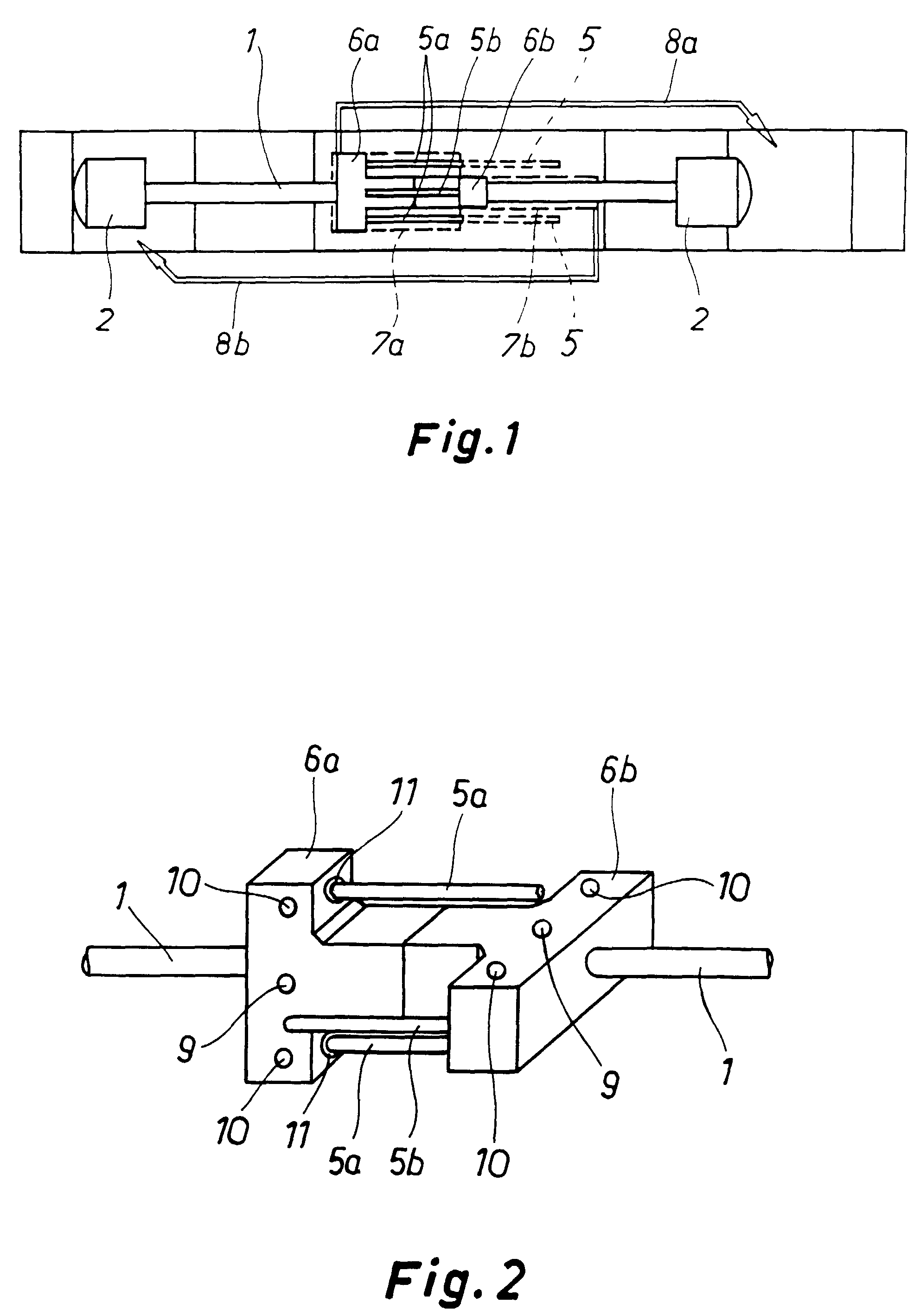
- fig. 1
- shows schematically a free-piston engine including a multi-piston hydraulic pump of
the invention, and
- fig. 2
- is a perspective view showing the hydraulic pump pistons with mounting blocks therefor.
[0006] A free-piston engine includes two engine pistons 2 mounted on the opposite ends of
a piston rod 1. The piston rod 1 has its mid-section provided with axially spaced
scavenger pump pistons 6a and 6b, which are T-shaped blocks whose T-stems are parallel
and against each other and T-heads are crosswise, in the present case at an angle
of 90° relative to each other. Pin-shaped hydraulic pump pistons 5a are fastened to
the mounting block 6a. Respectively, two hydraulic pump pistons 5b are fastened to
the mounting block 6b. The hydraulic pistons 5a and 5b fastened to different mounting
blocks 6a and 6b are located for the most part side by side over the same section
of the axial length of the engine piston rod 1 and the free ends of pistons 5a point
in the direction opposite to that of the free ends of pistons 5b. By virtue of this
arrangement, it is possible to employ a multi-piston hydraulic pump having a length
which is as short as possible. Naturally, the number of pistons 5a and 5b may vary.
[0007] The mounting blocks 6a and 6b of the hydraulic pistons can also be used for another
purpose. They can also serve as pistons for the scavenger pumps of engine cylinders.
In this case, the scavenger pump pistons constituted by blocks 6a and 6b operate in
cylinder spaces 7a and 7b made in the engine body, said spaces being connected by
way of scavenging ducts 8a and 8b to respective engine cylinders.
[0008] The piston rod 1 extends through holes bored centrally in blocks 6a and 6b and the
blocks 6a and 6b are fastened to the piston rod 1 by means of crosswise fastening
pins 9. The pin pistons 5a and 5b are secured to blocks 6a and 6b by means of crosswise
fastening pins 10. Receiving holes 11 for the bases of pin pistons 5a and 5b are made
loose and filled with resilient packings, whereby the pin pistons 5a and 5b are able
to find their way into pump cylinders 5 without setting unreasonably strict tolerances
for manufacturing.
1. A multi-piston hydraulic pump for a free-piston engine, comprising two engine pistons
(2) mounted on a common piston rod (1) which is also fitted with pin-shaped pistons
(5a, 5b) of the hydraulic pump at a radial distance from the piston rod (1), and mounting
blocks (6a, 6b) for the hydraulic pump pistons (5a, 5b) extend from the engine piston
rod (1) at a distance from each other and the free ends of the hydraulic pistons (5a,
5b) point in opposite directions, characterized in that the mounting blocks (6a, 6b) of the hydraulic pistons extend crosswise relative
to each other and that the hydraulic pistons (5a and 5b) fastened to different mounting
blocks (6a and 6b) are located for the most part side by side over the same section
of the axial length of the engine piston rod.
2. A hydraulic pump as set forth in claim 1, characterized in that said mounting blocks (6a, 6b) of the hydraulic pistons serve at the same
time as pistons for the scavenger pumps of engine cylinders, having their cylinder
spaces (7a, 7b) connected by way of scavenging ducts (8a, 8b) to respective engine
cylinders.
1. Flüssigkeitspumpe mit mehreren Kolben für einen Freikolbenmotor,
bestehend aus zwei Motorkolben (2), befestigt an einer gemeinsamen Kolbenstange (1),
die außerdem in einem radialen Abstand zur Kolbenstange (1) mit bolzenförmigen Kolben
(5a, 5b) der Flüssigkeitspumpe versehen ist
und Halteteile (6a, 6b) für die Kolben (5a, 5b) der Flüssigkeitspumpe, die sich in
einem Abstand zueinander von der Motor-Kolbenstange (1) erstrecken
wobei die freien Enden der hydraulischen Kolben (5a, 5b) in entgegengesetzte Richtungen
weisen
dadurch gekennzeichnet,
dass die Halteteile (6a, 6b) der hydraulischen Kolben (5a, 5b) sich relativ zueinander
kreuzweise erstrecken
und dass die an unterschiedlichen Halteteile (6a, 6b) befestigten hydraulischen Kolben
(5a, 5b) größtenteils Seite an Seite über den gleichen Abschnitt der axialen Länge
der Motorkolbenstange (1) angeordnet sind.
2. Flüssigkeitspumpe nach Anspruch 1, dadurch gekennzeichnet, dass die Halteteile (6a,
6b) der hydraulischen Kolben (5a, 5b) gleichzeitig als Kolben für die Spülpumpen der
Motorzylinder dienen, deren Zylinderraum (7a, 7b) durch Spülleitungen (8a, 8b) mit
dem jeweiligen Motorzylinder verbunden sind.
1. Pompe hydraulique multipiston pour moteur à pistons libres, comprenant deux pistons
de moteur (2) montés sur une tige de pistons commune (1) qui est aussi munie de pistons
en forme de broche (5a, 5b) de la pompe hydraulique à une distance radiale de la tige
de pistons (1), et où des blocs de montage (6a, 6b) pour les pistons de pompe hydraulique
(5a, 5b) s'étendent de la tige de pistons (1) du moteur à une distance l'un de l'autre
et les extrémités libres des pistons hydrauliques (5a, 5b) sont orientées dans des
directions opposées, caractérisée en ce que les blocs de montage (6a, 6b) des pistons
hydrauliques sont disposés transversalement l'un par rapport à l'autre et en ce que
les pistons hydrauliques (5a et 5b) fixés à des blocs de montage différents (6a et
6b) sont situés pour la plus grande partie côte à côte sur la même section de la longueur
axiale de la tige de pistons du moteur.
2. Pompe hydraulique selon la revendication 1, caractérisée en ce que lesdits blocs de
montage (6a, 6b) des pistons hydrauliques servent en même temps de pistons pour les
pompes de balayage des cylindres du moteur, leurs espaces de cylindres (7a, 7b) étant
reliés par des conduits de balayage (8a, 8b) aux cylindres de moteur respectifs.