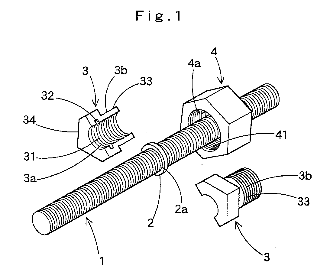
(57) The lock nut device is constituted by a nut setting member fitted loosely to an outer
circumferential part of a screw shaft such as a bolt; split nuts (3,3) divided in
two in axial direction and fitted so as to envelope the outside of the nut setting
member fitted to the screw shaft, the slit nuts having an inner screw and a locking
groove into which the nut setting member (2) is to be fitted at an inner surface and
having an outer screw in taper shape at an outer circumferential part; and a lock
nut (4) having an inner screw (4a) to be threadedly engaged with the outer screw in
taper shape of the split nuts (3,3). In order to fix a nut to a screw shaft such as
a bolt (1), the nut setting member (2) is put around the outer circumferential part
of the screw shaft and stood still to a prescribed position. The split nuts (3,3)
divided in two are fitted so as to envelope the outer circumference of the screw shaft
and the nut setting member (2). The nut setting member is fitted into a locking groove
(32) provided at the inner circumference of the split nuts (3,3), and the inner screw
(3a,3a) of the split nuts (3,3) is fitted to the thread of the screw shaft. Thus the
split nuts (3,3) divided in two are held in the assembled state in one body at a desired
position of the outer circumferential part of the screw shaft by the fitting of the
locking groove (32) at the inside and the nut setting member (2). In this state, the
lock nut (4) is threadedly engaged with the outer circumferential part (3b) of the
split nuts (3,3) and is tightened.
|
|
