| (19) |
 |
|
(11) |
EP 0 608 378 B1 |
| (12) |
EUROPEAN PATENT SPECIFICATION |
| (45) |
Mention of the grant of the patent: |
|
15.12.1999 Bulletin 1999/50 |
| (22) |
Date of filing: 21.10.1992 |
|
| (86) |
International application number: |
|
PCT/US9209/105 |
| (87) |
International publication number: |
|
WO 9308/092 (29.04.1993 Gazette 1993/11) |
|
| (54) |
ONE-PIECE FITMENT AND CAP WITH TAMPER-EVIDENT BAND
EINSTÜCKIGER SPUND UND KAPPE MIT GARANTIEBAND
UNITE EMBOUT ET BOUCHON POURVUS D'UNE BANDE REVELANT UNE TENTATIVE D'OUVERTURE
|
| (84) |
Designated Contracting States: |
|
AT DE ES FR GB IT |
| (30) |
Priority: |
22.10.1991 US 780774
|
| (43) |
Date of publication of application: |
|
03.08.1994 Bulletin 1994/31 |
| (73) |
Proprietor: PORTOLA PACKAGING, INC. |
|
San Jose
California 95112 (US) |
|
| (72) |
Inventors: |
|
- LUCH, Daniel
San Jose, CA 95112 (US)
- ADAMS, Brian, M.
San Jose, CA 95112 (US)
|
| (74) |
Representative: McLeish, Nicholas Alistair Maxwell et al |
|
Boult Wade Tennant
27 Furnival Street
London EC4A 1PQ
London EC4A 1PQ (GB) |
| (56) |
References cited: :
FR-A- 2 639 916
US-A- 3 998 354
US-A- 4 360 113
|
GB-A- 2 075 477
US-A- 4 345 690
US-A- 4 972 568
|
|
| |
|
|
|
|
| |
|
| Note: Within nine months from the publication of the mention of the grant of the European
patent, any person may give notice to the European Patent Office of opposition to
the European patent
granted. Notice of opposition shall be filed in a written reasoned statement. It shall
not be deemed to
have been filed until the opposition fee has been paid. (Art. 99(1) European Patent
Convention).
|
BACKGROUND OF THE INVENTION
1. Field of the Invention
[0001] This invention relates to a new and improved spout fitment and a plug type cap for
closing same. More particularly, the invention relates to a fitment which fits around
a hole in a panel of a paperboard carton or around a hole in a flexible container,
or the like, such as used for packaging liquid products and powders and to a closure
for such fitment.
2. Description of Related Art
[0002] Generally speaking, prior fitments have spouts with external threads closed by caps
with internal threads. Some fitments are used in conjunction with plastic bag containers,
the fitment being integrally welded to the plastic bag. Other prior art fitments are
attached to a polymer-coated paperboard container such as a gable-top half-gallon
container. Generally, prior art fitments for paperboard cartons include a thin flange
which is welded to the surface of the container. The closure includes a foil seal
which seals the mouth of the spout and a liner for the cap which serves a resealing
function. Attachment to the polymer coated paperboard is accomplished by welding the
flange of the spout to the polymer coating. Upon initial removal, the tamper-evident
foil seal is removed and discarded.
[0003] Fitments of the prior art have a number of deficiencies as compared to the present
invention. In the first place, they employ multiple components which increase the
cost of the combination very greatly over the simple structure of the present invention.
Secondly, the assembly is difficult and involves rotary equipment which is difficult
to control in practice and is expensive to install. Thirdly, because of the fact that
the prior art spouts are externally threaded, the diameter of the opening in the spout
is restricted inasmuch as there is only limited space on the panel of the container
on which the flange can be located, thereby reducing the diameter of the fitment flange
and correspondingly the internal diameter of the spout. Finally, commercially available
fitment-closure combinations have no external tamper-evident features, demonstrated,
for example, by the internal foil seal of the spout opening of the prior art.
[0004] All of the foregoing deficiencies are eliminated in the present invention.
SUMMARY OF THE INVENTION
[0005] The present invention comprises in combination, a fitment and a cap therefor, said
fitment comprising an annular flange having a hole, a spout upstanding from said flange
surrounding said hole, and first helical attachment means on said spout, said cap
having a top, a skirt depending from said top, second helical attachment means on
said skirt co-operable with said first helical attachment means to tighten said cap
on said fitment when said cap is turned in a first direction and loosen said cap when
said cap is turned in a second direction opposite said first direction, a tamper-evident
ring surrounding said skirt, frangible means detachably connecting said ring to said
skirt, and first locking means attached to said ring, complementary second locking
means being fixed to said fitment shaped and positioned to receive said first locking
means to restrain loosening said cap so long as said frangible means is intact, said
first locking means comprising a finger depending from said ring and said second locking
means comprising a socket shaped and positioned to receive said finger.
[0006] Initially, the cap and fitment are preferably molded in a mingle mold and the two
parts are connected together by frangible bridges or gates joining the cap skirt and
the upper edge of the fitment spout. Either in the final stage of the molding process
or separately, the cap is depressed relative to the fitment by a straight axial push.
The helical attachment means of the cap and spout slip over each other in this operation
and seat in liquid-tight fashion. At the same time the fingers of the taper-evident
band are inserted into the sockets in the fitment. In this position, the cap cannot
be unscrewed without removal of the tamper-evident band. The fitment flange is then
attached to the container and the container is filled.
[0007] The consumer pulls off the tamper-evident band and then unscrews the cap.
BRIEF DESCRIPTION OF THE DRAWINGS
[0008] The accompanying drawings, which are incorporated in and form a part of this specification,
illustrate embodiments of the invention and, together with the description, serve
to explain the principles of the invention:
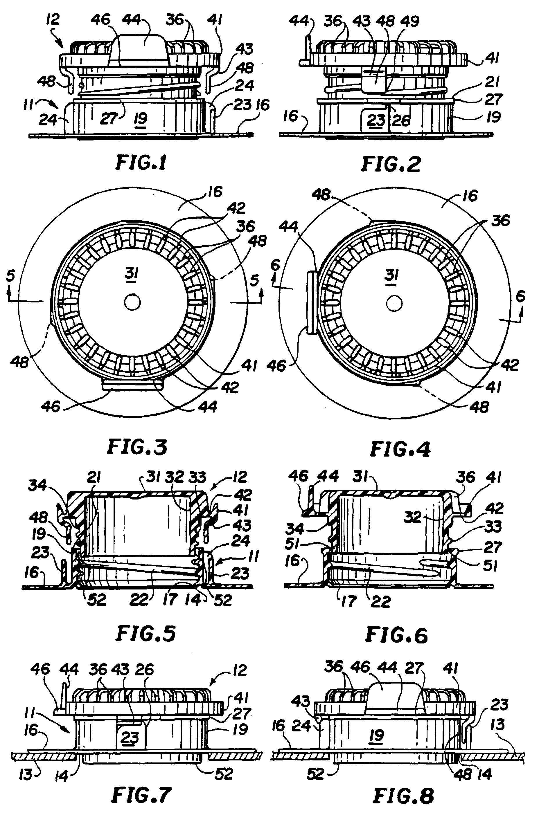
Fig. 1 is a side elevational view of the cap and fitment prior to assembly.
Fig. 2 is a view similar to Fig. 1 rotated 90 degrees.
Fig. 3 is a top plan view of the structure of Fig. 1.
Fig. 4 is a top plan view of the structure of Fig. 2.
Fig. 5 is a sectional view taken substantially along the line 5--5 of Fig. 3.
Fig. 6 is a sectional view taken substantially along the line 6--6 of Fig. 4.
Fig. 7 is a view showing the cap assembled in the fitment and attached to a supporting
container surface.
Fig. 8 is a view similar to Fig. 7 rotated 90 degrees.
DETAILED DESCRIPTION OF THE PREFERRED EMBODIMENT
[0009] Reference will now be made in detail to the preferred embodiments of the invention,
examples of which are illustrated in the accompanying drawings. While the invention
will be described in conjunction with the preferred embodiments, it will be understood
that they are not intended to limit the invention to those embodiments. On the contrary,
the invention is intended to cover alternatives, modifications and equivalents, which
are included within the scope of the invention as defined by the appended claims.
[0010] The present invention comprises a fitment portion 11 and a cap portion 12. As shown
in Fig. 7, the fitment is attached to a carton panel 13 having a hole 14 therein.
It will be understood that the invention may be used with other container constructions.
[0011] Fitment portion 11 has an annular flange 16 which is attached to the container panel
13 surrounding the hole 14 therein. A downward-inward projection 17 on the lower edge
of the inside of the flange 16 extends into the hole 14 in the panel 13. Plug seal
surface 52 is formed on the exterior of the plug skirt vicinal its lower end. When
assembled, plug seal surface 52 contacts flange 17 to form a primary seal for the
assembly. It is noted that this arrangement permits both flange 17 and seal surface
52 to be molded without seam lines to ensure effective sealing. Various means may
be used to join the flange 16 to the panel 13. Welding the flange to the panel is
a preferred choice in the present invention.
[0012] Projecting upward from the inside of the flange 16 is a spout 19 having a top edge
21. Internal threads 22 are formed in the spout 19. Spaced outwardly of spout 19 and
projecting upward from flange 16 is a socket wall 23 which is parallel to a tangent
to the outside of the spout 19. One end of wall 23 is closed off by a radial socket
wall end 24. As shown in the accompanying drawings, there are two socket walls 23
diametrically spaced apart. It will be understood that a single socket or more than
two sockets may be used. Socket wall 23 has an upward projection 26 which joins the
socket end wall 24, as best shown in Fig. 2. The outer wall of spout 19 is formed
with an upward projecting peripheral flange 27 immediately below its top edge 21.
The flange 27 is continuous except immediately above socket walls 23.
[0013] Cap portion 12 has a top disk 31 from which depends skirt 32, which is formed with
external threads 33 to mate with the threads 22. Shoulder 34 is formed at the upper
end of the threads 33. External ribs 36 curve from the periphery of top disk 31 downwardly
and assist the user in gripping the cap portion 12 to unscrew it from the fitment.
Surrounding skirt 32 and spaced outwardly thereof is a horizontal tamper-evident band
41. The lower edge of band 41 is connected to the skirt 32 by frangible bridges 42
which may constitute extensions of the lower edges of ribs 36. Thus the bridges 42
alternate with voids therebetween to form a line of weakness between band 41 and skirt
32. It will be understood that other means may be used to create a line of weakness
between the band 41 and the skirt 32. In at least one location, there is an upward-extending
pull tab 44 integral with the band 41 and projecting upward so that it may be conveniently
gripped by the consumer to tear off the band 41. As a further means to facilitate
tearing off the band 41, at least one outward-projecting thumb tab 46 is provided.
Thus the consumer may either grip the tab 44 and pull upward or insert a finger or
thumb under the tab 46 and pull upward to remove band 41.
[0014] Extending downward from band 41 in one or more locations (here shown as two in number)
are tamper-evident fingers 48 which are shaped parallel to a tangent drawn to the
exterior of skirt 32. The fingers 48 are joined to the band 41 by downward-inward
curved connections 43.
[0015] The cap portion 12 and fitment portion 11 are initially connected together by frangible
radial lugs or gates 51 joining the edge of skirt 32 to the top edge 21 of spout 19.
The lugs or gates are preferably positioned radially to coincide with the projected
extension of helical thread 33, so that the gates form an effective thread runout.
As illustrated, there are two diametrically spaced lugs 51, subject to variation.
This is because the embodiment shown is a double lead thread. Either during a final
ejection stage of the molding process or subsequently, the cap 12 is pushed down so
that the skirt 32 slips inside the spout 19. Threads 33 and 22 are so shaped and positioned
that they will slip past each other in registration during this downward movement.
The fingers 48 are so located with reference to the socket walls 23 that a straight
downward push of the cap 12 seats the fingers 48 inside the socket walls 23 and adjacent
the socket end walls 24.
[0016] End walls 24 prevent the cap 12 from being unscrewed because the fingers 48 abut
thereagainst. If one attempts to unscrew the cap 12, the fingers 48 encountering the
walls 24 prevent such turning. If the consumer forces turning of the cap 12, fracture
of the bridges 42 occurs, thereby giving evidence of tampering.
[0017] In a preferred use of the device, the consumer either pulls upward on tab 44 or raises
the tab 46, causing the band 41 to be disconnected from the cap 12 by fracturing the
bridges 42. The cap 12 may then be unscrewed. Cap 12, of course, serves as a reclosure
cap until the contents of the container are consumed.
[0018] The foregoing descriptions of specific embodiments of the present invention have
been presented for purposes of illustration and description. They are not intended
to be exhaustive or to limit the invention to the precise forms disclosed, and obviously
many modifications and variations are possible in light of the above teaching. The
embodiments were chosen and described in order to best explain the principles of the
invention and its practical application, to thereby enable others skilled in the art
to best utilize the invention and various embodiments with various modifications as
are suited to the particular use contemplated. It is intended that the scope of the
invention be defined by the Claims appended hereto.
1. In combination, a fitment (11) and a cap (12) therefor, said fitment (11) comprising
an annular flange (16) having a hole, a spout (19) upstanding from said flange (16)
surrounding said hole, and first helical attachment means (22) on said spout (19),
said cap (12) having a top (31), a skirt (32) depending from said top (31), second
helical attachment means (33) on said skirt (32) co-operable with said first helical
attachment means (22) to tighten said cap (12) on said fitment (11) when said cap
(12) is turned in a first direction and loosen said cap (12) when said cap (12) is
turned in a second direction opposite said first direction, a tamper-evident ring
(41) surrounding said skirt (32), frangible means (42) detachably connecting said
ring (41) to said skirt (32), and first locking means (48) attached to said ring (41),
complementary second locking means (23) being fixed to said fitment (11) shaped and
positioned to receive said first locking means (48) to restrain loosening said cap
(12) so long as said frangible means (42) is intact, said first locking means (48)
comprising a finger depending from said ring (41) and said second locking means (23)
comprising a socket shaped and positioned to receive said finger.
2. The combination according to claim 1 in which said first helical attachment means
(22) comprises internal threads on said spout (19) and said second helical attachment
means (33) comprises external threads on said skirt (32) mating with said internal
threads.
3. The combination according to claim 1 in which said finger (48) depends vertically
from said ring (41) and is spaced outward from the exterior of said skirt (32).
4. The combination of claim 1 which further comprises at least one downward-inward connection
(43) extending from a bottom edge of said ring (41) and connected to a top of said
finger (48).
5. The combination of claim 1 in which said frangible means (42) comprises thin bridges
separated by spaces extending inwardly from said ring (41) to said skirt (32).
6. The combination of claim 1 which further comprises radial finger-grip ribs (36) spaced
around the exterior of said skirt (32).
7. The combination of claim 1 in which said finger (48) is rectangular in cross-section,
the width of said finger (48) being positioned parallel to a horizontal tangent to
said skirt (32).
8. The combination of claim 7 in which said socket (23) comprises a vertical socket wall
disposed outwardly relative to said finger (48).
9. The combination of claim 8 in which said socket wall (23) is substantially parallel
to a tangent to said spout (19).
10. The combination of claim 8 which further comprises a substantially radial socket end
wall (24) extending substantially radially between one end of said socket wall (23)
and the exterior of said spout (19).
11. The combination of claim 1 which further comprises a pull tab (44) fixed to and extending
upwardly from said ring (41), whereby pulling said tab (44) breaks said frangible
means (42).
12. The combination of claim 1 which further comprises a thumb tab (46) extending substantially
horizontally outward from said ring (41), whereby lifting said thumb tab (46) breaks
said frangible means (42).
13. The combination of claim 1 which further comprises lugs (51) initially interconnecting
said cap (12) and said fitment (11) whereby said cap (12) and said fitment (11) may
be injection molded in one piece.
14. The combination of claim 13 in which said lugs (51) are frangible and said first and
second helical attachment means (22,33) are sufficiently flexible so that said cap
(12) and spout (19) may be pressed together in an axial movement, said lugs (51) breaking
and said helical attachment means (22,33) slipping past each other to fully seat said
skirt (32) on said spout (19).
15. The combination of claim 14 wherein said lugs (51) are opposite the lower ends of
said second helical attachment means (33) and comprise thread runouts after said cap
(12) is separated from said fitment (11).
16. The combination of claim 1 wherein said finger (48) is positioned immediately above
said socket (23) prior to the breaking of said lugs (51) whereby said axial movement
seats said finger (48) in said socket (23).
17. The combination of claim 1 which further comprises an inward projection (17) at the
lower edge of said spout (19) and a downward projection (52) on the lower end of said
cap skirt (32) positioned to seal against said inward projection (17) when said cap
(12) is seated on said spout (19).
1. Kombination aus einem Aufsatz (11) und einer Kappe (12) für diesen Aufsatz (11), der
einen Ringflansch (16) mit einem Loch, einen Ausguß (19), der von dem das Loch umschließenden
Flansch (16) hochsteht, und eine erste schraubenförmige Befestigungseinrichtung (22)
an dem Ausguß (19) aufweist, während die Kappe (12) ein Oberteil (31), eine von dem
Oberteil (31) nach unten abstehende Einfassung (32), eine zweite schraubenförmige
Befestigungseinrichtung (33) an der Einfassung (32), die mit der ersten schraubenförmigen
Befestigungseinrichtung (22) zum Festziehen der Kappe (12) auf dem Aufsatz (11), wenn
die Kappe (12) in eine erste Richtung gedreht wird, und zum Lösen der Kappe (12),
wenn die Kappe (12) in eine zweite Richtung entgegengesetzt zur ersten Richtung gedreht
wird, in Zusammenwirkung bringbar ist, einen die Einfassung (32) umschließenden Originalsicher-Ring
(41), Aufbrecheinrichtungen (42), welche den Ring (41) lösbar mit der Einfassung (32)
verbinden, und eine erste Arretiereinrichtung (48) aufweist, die an dem Ring (41)
befestigt ist, wobei eine komplementäre zweite Arretiereinrichtung (23) an dem Aufsatz
(11) festgelegt und für die Aufnahme der ersten Arretiereinrichtung (48) geformt und
positioniert ist, um ein Lösen der Kappe (12) so lange zu verhindern, wie die Aufbrecheinrichtung
(42) intakt ist, die erste Arretiereinrichtung (48) einen von dem Ring (41) nach unten
ragenden Finger hat und die zweite Arretiereinrichtung (23) eine Hülse aufweist, die
für die Aufnahme des Fingers geformt und positioniert ist.
2. Kombination nach Anspruch 1, bei welcher die erste schraubenförmige Befestigungseinrichtung
(22) ein Innengewinde an dem Ausguß (19) und die zweite schraubenförmige Befestigungseinrichtung
(33) ein Außengewinde an der Einfassung (32) aufweist, das mit dem Innengewinde zusammenpaßt.
3. Kombination nach Anspruch 1, bei welcher der Finger (48) vertikal von dem Ring (41)
nach unten ragt und in einem Abstand nach außen von der Außenseite der Einfassung
(32) angeordnet ist.
4. Kombination nach Anspruch 1, welche weiterhin wenigstens eine Abwärts-Einwärts-Verbindung
(43) aufweist, die sich von einem unteren Rand des Rings (41) aus erstreckt und mit
der Oberseite des Fingers (48) verbunden ist.
5. Kombination nach Anspruch 1, bei welcher die Aufbrecheinrichtungen (42) dünne, durch
Zwischenräume getrennte Brücken aufweist, die sich nach innen von dem Ring (41) zur
Einfassung (32) erstrecken.
6. Kombination nach Anspruch 1, welche weiterhin radiale Fingergreifrippen (36) aufweist,
die im Abstand um die Außenseite der Einfassung (32) angeordnet sind.
7. Kombination nach Anspruch 1, bei welcher der Finger (48) einen rechteckigen Querschnitt
hat, wobei die Breite des Fingers (48) parallel zu einer horizontalen Tangente an
die Einfassung (32) angeordnet ist.
8. Kombination nach Anspruch 7, bei welcher die Hülse (23) eine vertikale Hülsenwand
aufweist, die bezüglich des Fingers (48) nach außen angeordnet ist.
9. Kombination nach Anspruch 8, bei welcher die Hülsenwand (23) im wesentlichen parallel
zu einer Tangente an den Ausguß (19) ist.
10. Kombination nach Anspruch 8, welche weiterhin eine im wesentlichen radiale Hülsenstirnwand
(24) aufweist, die sich im wesentlichen radial zwischen einem Ende der Hülsenwand
(23) und der Außenseite des Ausgusses (19) erstreckt.
11. Kombination nach Anspruch 1, welche weiterhin eine Zuglasche (44) aufweist, die an
dem Ring (41) festgelegt ist und sich von ihm nach oben erstreckt, so daß beim Ziehen
an der Lasche (44) die Aufbrecheinrichtungen (42) brechen.
12. Kombination nach Anspruch 1, welche weiterhin eine Daumenlasche (46) aufweist, die
sich im wesentlichen horizontal von dem Ring (41) nach außen erstreckt, so daß ein
Anheben der Daumenlasche (46) die Aufbrecheinrichtungen (42) bricht.
13. Kombination nach Anspruch 1, welche weiterhin Nasen (51) aufweist, die anfänglich
die Kappe (12) und den Aufsatz (11) verbinden, wodurch die Kappe (12) und der Aufsatz
(11) in einem Stück spritzgegossen werden können.
14. Kombination nach Anspruch 13, bei welcher die Nasen (51) zerbrechbar und die erste
und die zweite schraubenförmige Befestigungseinrichtung (22, 23) ausreichend flexibel
sind, so daß die Kappe (12) und der Ausguß (19) in einer axialen Bewegung zusammengedrückt
werden können, wobei die Nasen (51) brechen und die schraubenförmigen Befestigungseinrichtungen
(22, 23) aneinander vorbei rutschen, um die Einfassung (32) an dem Ausguß (19) vollständig
einzupassen.
15. Kombination nach Anspruch 14, bei welcher die Nasen (51) den unteren Enden der zweiten
schraubenförmigen Befestigungseinrichtung (33) gegenüberliegen und Gewindeausläufer
aufweisen, nachdem die Kappe (12) von dem Aufsatz (11) getrennt worden ist.
16. Kombination nach Anspruch 1, bei welcher der Finger (48) vor dem Brechen der Nasen
(51) unmittelbar über der Hülse (23) angeordnet ist, wodurch die Axialbewegung den
Finger (48) in die Hülse (23) einpaßt.
17. Kombination nach Anspruch 1, welche weiterhin einen Einwärtsvorsprung (17) an dem
unteren Rand des Ausgusses (19) und einen Abwärtsvorsprung (52) an dem unteren Ende
der Kappeneinfassung (32) aufweist, der so angeordnet ist, daß er gegen den Einwärtsvorsprung
(17) abdichtet, wenn die Kappe (12) an dem Ausguß (19) eingepaßt ist.
1. Ensemble constitué par un embout (11) et un bouchon (12) pour l'embout, ledit embout
(11) comprenant un rebord annulaire (16) comportant un orifice, un bec (19) se dressant
depuis ledit rebord (16) entourant ledit orifice, et un premier moyen de fixation
hélicoïdal (22) sur ledit bec (19), ledit bouchon (12) comportant un sommet (31),
une jupe (32) pendant depuis ledit sommet (31), un second moyen de fixation hélicoïdal
(33) sur ladite jupe (32) adapté à coopérer avec ledit premier moyen de fixation hélicoïdal
(22) de manière à serrer ledit bouchon (12) sur ledit embout (11) lorsque ledit bouchon
(12) est tourné dans une première direction et à desserrer ledit bouchon (12) lorsque
ledit bouchon (12) est tourné dans une seconde direction à l'opposé de ladite première
direction, une bague à preuve d'ouverture (41) entourant ladite jupe (32), un moyen
susceptible de rupture (42) reliant, avec possibilité de séparation, ladite bague
(41) à ladite jupe (32), et un premier moyen de blocage (48) fixé à ladite bague (41),
un second moyen de blocage complémentaire (23) étant fixé audit embout (11) façonné
et positionné de manière à recevoir ledit premier moyen de blocage (48) afin d'empêcher
un desserrage du bouchon (12) tant que ledit moyen susceptible de rupture (42) est
intact, ledit premier moyen de blocage (48) comprenant un doigt partant en descendant
de ladite bague (41) et ledit second moyen de blocage (23) comprenant une douille
façonnée et positionnée de manière à recevoir ledit doigt.
2. Ensemble selon la revendication 1, dans lequel ledit premier moyen de fixation hélicoïdal
(22) comprend des filets internes sur ledit embout (19) et ledit second moyen de fixation
hélicoïdal (33) comprend des filets externes sur ladite jupe (32) s'emboîtant avec
lesdits filets internes.
3. Ensemble selon la revendication 1, dans lequel ledit doigt (48) descend verticalement
de ladite bague (41) et est espacé vers l'extérieur de l'extérieur de ladite jupe
(32).
4. Ensemble selon la revendication 1 qui comprend également au moins une connexion vers
le bas et vers l'intérieur (43) s'étendant depuis un bord inférieur de ladite bague
(41) et reliée à un sommet dudit doigt (48).
5. Ensemble selon la revendication 1, dans lequel ledit moyen susceptible de rupture
(42) comprend de minces ponts séparés par des espaces s'étendant vers l'intérieur
de ladite bague (41) à ladite jupe (32).
6. Ensemble selon la revendication 1 qui comprend également des nervures de préhension
radiales (36) espacées autour de l'extérieur de ladite jupe (32).
7. Ensemble selon la revendication 1, dans lequel ledit doigt (48) est rectangulaire
en section transversale, la largeur dudit doigt (48) étant positionnée parallèlement
à une tangente horizontale à ladite jupe (32).
8. Ensemble selon la revendication 7, dans lequel ladite douille (23) comprend une paroi
de douille verticale disposée vers l'extérieur relativement audit doigt (48).
9. Ensemble selon la revendication 8, dans lequel ladite paroi de douille (23) est sensiblement
parallèle à une tangente audit bec (19).
10. Ensemble selon la revendication 8 qui comprend également une paroi d'extrémité de
douille sensiblement radiale (24) s'étendant sensiblement radialement entre une extrémité
de ladite paroi de douille (23) et l'extérieur dudit bec (19).
11. Ensemble selon la revendication 1 qui comprend également une languette à tirer (44)
fixée à, et s'étendant vers le haut depuis, ladite bague (41), de manière que la traction
de ladite languette (44) rompe ledit moyen susceptible de rupture (42).
12. Ensemble selon la revendication 1 qui comprend également une languette à pouce (46)
s'étendant sensiblement horizontalement vers l'extérieur de ladite bague (41), de
manière que le soulèvement de ladite languette à pouce (46) rompe ledit moyen susceptible
de rupture (42).
13. Ensemble selon la revendication 1 qui comprend également des pattes (51) reliant initialement
ledit bouchon (12) avec ledit embout (11) de manière que ledit bouchon (12) et ledit
embout (11) puissent être moulés par injection en une seule pièce.
14. Ensemble selon la revendication 13, dans lequel lesdites pattes (51) sont susceptibles
de rupture et lesdits premier et second moyens de fixation hélicoïdaux (22, 33) sont
suffisamment flexibles pour que ledit bouchon (12) et ledit bec (19) puissent être
conjointement pressés selon un mouvement axial, lesdites pattes (51) se rompant et
lesdits moyens de fixation hélicoïdaux (22, 33) glissant l'un au-delà de l'autre de
manière à asseoir complètement ladite jupe (32) sur ledit bec (19).
15. Ensemble selon la revendication 14, dans lequel lesdites pattes (51) sont opposées
aux extrémités inférieures dudit second moyen de fixation hélicoïdal (33) et comprennent
des fins de filets une fois ledit bouchon (12) séparé dudit embout (11).
16. Ensemble selon la revendication 1, dans lequel ledit doigt (48) est positionné juste
au-dessus de ladite douille (23) avant la rupture desdites pattes (51) de manière
que ledit mouvement axial fasse siéger ledit doigt (48) dans ladite douille (23).
17. Ensemble selon la revendication 1 qui comprend également une projection vers l'intérieur
(17) au bord inférieur dudit bec (19) et une projection vers le bas (52) sur l'extrémité
inférieure de ladite jupe (32) du bouchon positionnée de manière à se sceller de manière
étanche contre ladite projection vers l'intérieur (17) lorsque ledit bouchon (12)
siège sur ledit bec (19).