| (19) |
 |
|
(11) |
EP 0 975 051 A1 |
| (12) |
EUROPEAN PATENT APPLICATION |
| (43) |
Date of publication: |
|
26.01.2000 Bulletin 2000/04 |
| (22) |
Date of filing: 24.07.1998 |
|
| (51) |
International Patent Classification (IPC)7: H01R 9/05 |
|
| (84) |
Designated Contracting States: |
|
AT BE CH CY DE DK ES FI FR GB GR IE IT LI LU MC NL PT SE |
|
Designated Extension States: |
|
AL LT LV MK RO SI |
| (71) |
Applicant: Cabel-Con A/S |
|
DK-4760 Vordingborg (DK) |
|
| (72) |
Inventor: |
|
- Henningsen, Jimmy Ciesla
4700 Naestved (DK)
|
| (74) |
Representative: Roerboel, Leif et al |
|
Budde, Schou & Ostenfeld A/S,
Vestergade 31
1456 Copenhagen K
1456 Copenhagen K (DK) |
|
| |
|
| (54) |
Connector for coaxial cable with multiple start threads |
(57) Cable connector for coaxial cable, comprising a bushing (2) for providing an axial
displacement of parts (4,5,6,7,8) in the connector, whereby these parts are brought
into mechanical and/or electrical engagement with the coaxial cable. the axial displacement
is provided by screwing a thread (10) provided on the bushing (2) onto a corresponding
thread (9) provided on the main body (1) of the connector. By providing said threads
(9,10) as multiple-start threads, it is achieved, that the assembly time can be substantially
reduced.
|
|
[0001] The present invention relates to a cable connector of the kind set forth in the preamble
of claim 1.
[0002] In cable connectors of this kind it is known to use axially displaceable components
with conical formations coorperating to provide the radial compression of axially
slotted connecting parts, to provide the electrical and mechanical connections between
the connector and the coaxial cable. The axial displacement of parts in the connector
is effected by a bushing or collar provided with a thread, which is screwed onto a
corresponding thread provided in the main body of the connector. Due to the necessary
many rotations of the bushing the mounting time for such connectors is high. It is
known to eliminate this high mounting time by using a connector mounting method involving
crimping the connector with a crimping tool, but such connectors cannot be replaced
in a simple way, due to the inevitable damage on the cable when removing such a crimped
cable connector.
[0003] It is the object of the present invention to provide a cable connector of the above
kind, with which the mounting time can be reduced and this objects is achieved with
a connector of said kind, which according to the present invention is characterised
by the features set forth in the characterising clause of claim 1. With this arrangement
the bushing can be brought to it's final mounting position with only a few rotations
of the of the bushing and the thread is almost instantaneously engaged, whereas the
single thread of the Prior Art having only one start may have to be rotated up to
360° before it is brought into initial engagement.
[0004] Preferred embodiments of the connector are revealed in the subordinate claims 2 and
3. Claim 2 indicates a locking arrangement preventing rotation of the cable. Claim
3 indicates the provision of O-rings for providing a liquid and moisture tight connector.
[0005] In the following detailed portion of the present description the present invention
will be explained in more detail with reference to the exemplary embodiment of a cable
connector for coaxial cable according to the invention shown in the drawing in which
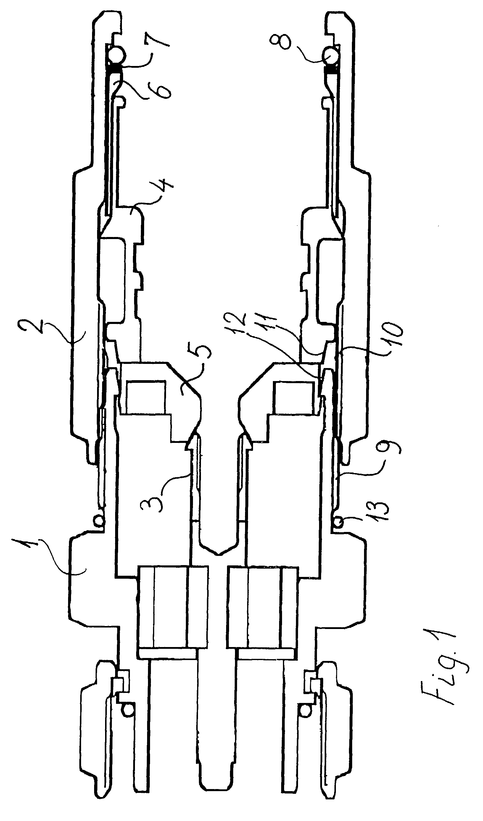
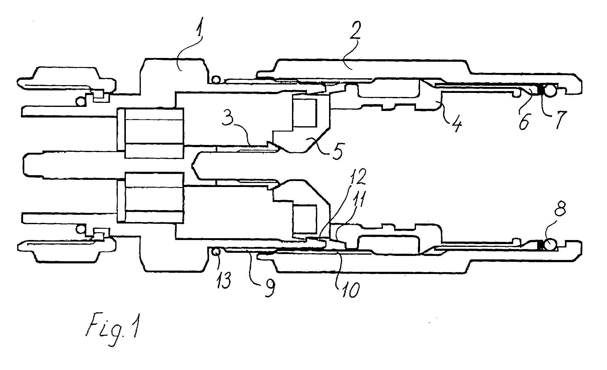
Fig 1 shows an axial cut through a cable connector for coaxial cable in accordance
with the invention.
[0006] The cable connector for coaxial cable shown in the figure comprises a main body 1,
which, as shown to the left in the drawing, is provided with a plug part in the form
of a BNC, TNC or the like. This plug part is not part of the invention and any suitable
connection may be provided in this place. The main body 1 is provided with threads
9 for engagement with corresponding threads 10 on a bushing or collar 2. Centrally
placed in the main body 1 is an axially slotted tube 3 for connection of the central
conductor of the coaxial cable. The axially slotted tube 3 will be radially compressed
by an axially displaceable insulating part 5 which is provided with a conical formation
for engaging the axially slotted tube 3. An axially slotted ferrule 4 for electrical
connection to the outer conductor of the coaxial cable and possibly for mechanical
connection to the outer insulating jacket of the cable is placed behind the axially
displaceable part 5 and the axial displacement of the ferrule 4 and the axially displaceable
part 5 is provided by screwing the bushing 2 onto the main body 1 whereby the bushing
moves an axially displaceable inner bushing 6 acting upon the ferrule 4. In the embodiment
shown a disc 7 and a O-ring 8 is placed between a step on the bushing 2 and the inner
bushing 6. A further O-ring 13 is provided on the main body 1 for providing a sealing
between the bushing 2 and main body 1 when the bushing 2 is brought into its final
position.
[0007] The cable connector shown in the drawing functions in the following way:
[0008] A prepared coaxial cable is inserted into the connector, the cable being prepared
in such a way, that the inner conductor can be inserted into the axially slotted tube
3 and the outer conductor and outer jacket can be positioned inside the ferrule 4.
The bushing 2 is screwed onto the main body 1 using the threads 9 and 10, whereby
the bushing moves the disc 7, the axially displaceable inner bushing 6, the axially
slotted ferrule 4 and the axially displaceable insulating part 5 whereby the axially
slotted tube 3 is compressed radially into contact with the central conductor of the
coaxial cable. The ferrule 4 is provided with a locking arrangement 11 which at the
end of the axial travel of the ferrule 4 is brought into engagement with a corresponding
locking arrangement 12 provided on the main body 1. The engagement between the two
locking arrangements 11,12 prevents the ferrule 4 from rotating relative to the main
body 1. Further axial movement of the bushing 2 will provide an axial movement of
the inner bushing 6, whereby the axially slotted ferrule 4 will be radially compressed
due to appropriate conical formations on the ferrule 4 cooperating with the inner
bushing 6, whereby the ferrule 4 is brought into engagement with the outer conductor
and the outer jacket on the coaxial cable. In the embodiment shown part of the radial
compression of the ferrule 4 is provided by engagement between the front of the inner
bushing 6 and a conical formation of the ferrule and other part of the radial compression
of the ferrule is provided by engagement between a conical formation on the inner
bushing 6 and the back part of the ferrule 4.
[0009] Above the present invention has been described in connection with a specific embodiment
of the invention, however it will be clear for a man skilled in the art, that many
alterations can be made without departing from the following claims.
1. Cable connector for coaxial cable, comprising a bushing (2) for providing an axial
displacement of parts (4,5,6,7,8) in the connector, whereby these parts are brought
into mechanical and/or electrical engagement with the coaxial cable, the axial displacement
being provided by screwing a thread (10) provided on the bushing (2) onto a corresponding
thread (9) provided on the main body (1) of the connector, characterised by, that said threads (9,10) are provided as multiple-start threads.
2. Cable connector (2) in accordance with claim 1, characterised by, that the parts in the connector, which are axially displaced by the bushing (2),
comprises a ferrule (4) for engaging the outer or screen of the coaxial cable, the
ferrule (4) comprising a locking arrangement (11) for preventing rotation of ferrule
(4) and cable, when screwing the bushing (2) onto the main body (1) of the connector.
3. Cable connector in accordance with any of the claims 1-2 characterised by further comprising O-rings (8,13) between the bushing (2) and the cable, and between
the bushing (2) and the main body (1) of the connector for providing a liquid and
moisture tight connector.