| (19) |
 |
|
(11) |
EP 0 581 946 B1 |
| (12) |
EUROPEAN PATENT SPECIFICATION |
| (45) |
Mention of the grant of the patent: |
|
02.02.2000 Bulletin 2000/05 |
| (22) |
Date of filing: 25.02.1993 |
|
| (51) |
International Patent Classification (IPC)7: F16K 47/04 |
| (86) |
International application number: |
|
PCT/ES9300/013 |
| (87) |
International publication number: |
|
WO 9317/265 (02.09.1993 Gazette 1993/21) |
|
| (54) |
REGULATION VALVE FOR HIGH PRESSURE SURGES
REGELVENTIL FUER GROSSE DRUCKFALLE
SOUPAPE DE REGULATION POUR A-COUPS DE PRESSION IMPORTANTS
|
| (84) |
Designated Contracting States: |
|
AT BE CH DE DK FR GB GR IE IT LI LU NL PT SE |
| (30) |
Priority: |
26.02.1992 ES 9200421
|
| (43) |
Date of publication of application: |
|
09.02.1994 Bulletin 1994/06 |
| (73) |
Proprietor: BADAIN, S.L. |
|
E-22364 Lafortunada-Huesca (ES) |
|
| (72) |
Inventor: |
|
- CAZCARRA PALLARUELO, Sebastian
E-50012 Zaragoza (ES)
|
| (74) |
Representative: Isern Jara, Nuria |
|
C/ Orense 64
28020 Madrid
28020 Madrid (ES) |
| (56) |
References cited: :
EP-A- 0 053 290
FR-A- 2 382 639
|
EP-A- 0 139 399
FR-A- 2 624 245
|
|
| |
|
|
|
|
| |
|
| Note: Within nine months from the publication of the mention of the grant of the European
patent, any person may give notice to the European Patent Office of opposition to
the European patent
granted. Notice of opposition shall be filed in a written reasoned statement. It shall
not be deemed to
have been filed until the opposition fee has been paid. (Art. 99(1) European Patent
Convention).
|
[0001] The objective of this application is a pressure reducing valve intended for high
pressure drops service, which offers outstanding innovations and important advantages
over existing control valves used in similar services.
[0002] It is wall known that when the pressure drops across a control valves is high, there
will be noise, vibrations and fast wearing of the parts of the valve which throttle
or control the flow, the plug, the seat ring and the cage or cylinder.
[0003] Also there is a friction between the moving parts, due to the difference in pressure
in the left-right sides of the valve (which is asimetric) and pushes in horizontal
direction the plug against the cylinder.
[0004] Also, if the plug is not balanced in the vertical direction, the force required by
the plug to be moved will be larger, and the movement will not be smooth unless oversized
actuators are used.
[0005] Referring to the state of the art, it has to be said that there are several types
of control valves, which either do not solve the problem or they solve the problem
in a complicated and costly way, as we are going to see.
[0006] A solution is to have 2 or more control valves one after the other, each of them
taking a part of the total pressure drop, which is an expensive solution.
[0007] There are also control valves having inside complex throttling cages, made of several
disc stacks or cylinders, one above or inside the other, which also divide the total
pressure drop across the valve in two or more pressure drops, but increasing enormously
the complexity of the desing and the cost, and also reducing the flow capacity of
the valve.
[0008] Also, the problem of the side forces, which give friction and wearing of plug and
cylinder, has not been solved yet. In existing desings large parts of the plug are
exposed to differential pressure around its cylindric surface, this giving side forces,
proportional to the surface and the pressure differences. It gives vibration sometimes,
friction and wearing in all cases. This is a particular serious problem in large size
valves.
[0009] By the document EP-0 053 290 a valve device is known provided with a lower cage in
which one diameter and several grooves can be noted. Said device also is comprised
of a plug with three different sections which correspond to an upper section with
two diameters, one of which having a throttling function, a grooved middle section
with an outer cage of sleeve, and a lower section which is hollow and keeps the same
diameters as the upper and middle sections. By this arrangement, the mentioned design
creates intermediate pressure inside the grooves of cavities in and around the plug
and the lower cage.
[0010] The new control valve which is the objet of this application, designed for high pressure
drop, reduces the total pressure drop in several stages, gradually, and eliminates
in a simple way the noise, vibration and wearing problems.
[0011] The new design of the internal parts of the valve makes the fluid to change direction
several times and creates also internal chambers which are intermediate steps or stages
of the pressure.
[0012] This design solves for the first time the problem of the side forces, by means of
the balancing ring chambers. These chambers are ring spaces around the plug which
balance the side forces acting in a horizontal direction. In this way the plug is
not pushed against the guiding cylinder and friction and wearing are reduced.
[0013] Also the plug has been designed with a middle chamber sized to allow the pass of
flow and to compensate the forces in the vertical direction. So the plug is balanced
at all positions along its stroke and the forces required to move it are very reduced.
[0014] To give a detailed description of the invention, reference will be made to the enclosed
figure, which, as an example and without being limited to, has been represented as
a preferred but not the only way of execution.
[0015] In the drawings:
- Figure 1
- represents a sectional view of the valve object of the invention.
- Figure 2
- represents a detail of figure 1
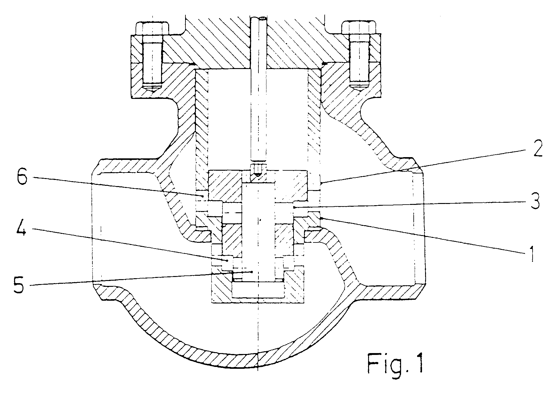
[0016] In figure 1 are shown the main parts of the valve:
(1) The seat ring which has a drilled cylinder in its lower side
(2) The cylinder also drilled and
(3) The plug which is hollow and has from top to botton three diameters decreasing
in size.
The design is based on the division of the total pressure drop on several minor pressure
drops. To achieve this it creates inner chambers or intermediate stages, in the way
of the flow, combining the different diameters of the plug with the correlated diameters
of the seat ring 2, 3, 4 or more steps as required by the total pressure drop.
In figure 2 a 4 stages pressure drop design is represented, having three chambers
or intermediate stages:
(4) A lower ring chamber around the plug (3) inside the seat ring (1).
(5) A middle chamber inside the plug (3).
(6) An upper chamber around the plug (3) inside the cylinder (2).
[0017] With this layout the flow comes from the high pressure side from under the seat ring
through the holes of the seat ring cylinder (1-4) which is the first restriction,
to the chamber (4) which is the first stage. Before it goes to the middle chamber,
the fluid has to pass a second pressure drop (4-5) across the lower part of the plug
to reach an intermediate pressure.
[0018] Until here the flow went from outside to inside the plug. From here it will go upwards
and then from inside to outside the plug. So the fluid goes through restriction (5-6)
in the upper part of the plug and reaches the chamber (6) which is the third pressure
stage. Finally after going to restriction (6-2) in the cylinder, the fluid reaches
output pressure.
[0019] In this simple way, with
one plug (3)
one seat ring (1) and
one cylinder (2), a high pressure drop across the valve is divided into 4 smaller pressure drops
and all the problems associated to a high pressure drop, are avoided.
[0020] Additionally the chambers (6) and (4) act as balancing chambers, and all horizontal
forces around the plug (3) are balanced.
[0021] So the plug (3) is not pushed in any horizontal direction (as commonly happens is
existing designs) because it is "floating" within the cylinder (2), reducing to a
minimum the friction and allowing a smooth vertical movement. The plug (3) is balanced
in horizontal direction.
[0022] Finally by selecting property the area of the chambers (6), (4) and (5) the plug
is also balanced in the vertical direction. In fact pressure in chambers (6) and (4)
pushes the plug (3) upwards. Pressure in chamber (5) pushes downwards the plug. The
correct sizing of the diameters of these chambers with make the upwards, and downwards
forces to be balanced. In this way the displacement of the plug will be smooth.
[0023] As a conclusion, the proposed design solves three different problems:
Eliminates noise and vibration associated to large pressure drop, by dividing total
pressure drop in several smaller pressure drops, in a very simple way, with a reduced
number of components.
[0024] Reduces friction of plug and cylinder, by creating balancing chambers around the
plug which suppresses horizontal forces, for the first time.
[0025] Reduces the force required to move the plug in the vertical direction, by a correct
sizing of the balancing chambers.
1. Control valve for high pressure drops, which includes seat ring (1), cylinder (2)
and plug (3), characterized in that said seat ring is an extended seat ring (1) with
a drilled lower part and, said plug is a one part hollow plug (3) with several diameters
decreasing in size from top to botton, which combine with the inside diameters of
cylinder and seat ring, and create intermediate chambers or pressure stages between
the inlet and the outlet pressure of the fluid, and because the pressure drop valve
of every stop is smaller than the total pressure drop valve, noise and vibration are
supressed.
2. Control valve, according to the above claim, characterized, in a preferred design,
by three intermediate chambers: one lower ring chamber (4) around the plug (3) between
this and the lower part of the seat ring (1), another cylindric chamber (5) within
the same plug and the upper chamber (6) between the plug and the cylinder (2), such
that the fluid in a first step goes from outside to inside, through the lower part
of a seat ring restriction (1-4) where the first step is stablished, then the fluid
has to go through a restriction (4-5) in the lower part of the plug, to the central
middle chamber (5), this is the second step, where the pressure valve is about the
middle value of the valve inlet and outlet pressures, then there being a change in
the direction of the fluid which goes from inside to outside the plug through a upper
restriction of the plug (5-6), to a chamber (6) which is the third pressure drop,
before going through a cylinder restriction (6-2) to the outlet of the valve, this
having in all 4 pressure steps (in this preferred design) each of them smaller than
the total pressure drop across the valve.
3. Control valve, according to claims 1 or 2 characterized, in that the ring chambers
(6, 4) around the upper and lower parts of the plug, having been performed as balancing
chambers, they compensate the horizontal forces acting on the plug, so that this is
now radially balanced and friction against guiding parts of seat ring and cylinder
are supressed.
4. Control valve, according to any of the preceding claims, characterized in that it
also comprises chambers (6), (4) and (5) which have been sized in such a way that
the vertical forces given by the chambers (4) and (6) on the plug (3), are compensated
by the vertical force given by the chamber (5), and the plug is also balanced in the
vertical direction, which makes easier and smoother the displacement of the plug when
controlling the flow of fluid.
1. Steurventil 1 für grosse Drucksprünge, mit einem Sitzring (1), einem Zylinder (2)
und einem Verschluss (3), dadurch gekennzeichnet, dass der genannte Sitzring ein gedehnter
Sitzring (1) ist, der ein mit Bohrungten versehenes Unterteil aufweist, wobei der
Verschluss ein hohler, einstückiger Verschluss (3) ist, mit, verschliedenen Durchmessern,
deren Grösse von oben nach unten abnimmt, wobei diese Durchmesser mit den Innendurchmessern
des Zylinders und des Sitzrings zusammenwirken, und Zwischenkammern beziehungsweise
Druckstufen zwischen dem Eingangs- und Ausgangsdruck der Flüssigkeit bilden, und dadurch,
dass der Drucksprung des Ventils an jeder Stufe kleiner ist als der Drucksprung des
gesamten Ventils, wodurch die Geräusche und die Schwingungen unterdrückt werden.
2. Steuerventil nach dem vorhergehenden Anspruch, dadurch gekennzeichnet, dass in einer
bevorzugen Ausführung drei Zwischenkammern geschaffen werden: eine untere ringförmige
kammer (4) um den Verschluss (3) zwischen letzterem und dem unteren Tei] des Sitzrings
(1), eine weitere zylinderförmige Kammer (5) im Inneren des cigentlichen Verschlusses
(2), und die obere Kammer (6) zwischen dem Verschluss und dem Zylinder (2), so dass
die Flüssigkeit in einer ersten Stufe über den unteren Teil einer Verengung (1-4)
des Sitzrings von aussen nach innen fliesst, wobei an dieser Verengung die erste stufe
gebildet wird, wonach die Flüssigkeit durch eine Verengung (4-5) am unteren Teil des
Verschlusses bis zur mittleren Kammer (5) fliesst, wobei dies die zweite Stufe darstellt,
in der das Druckventil ungefähr den Mittelwert des Eingangs- und Ausgangsdrucks des
Ventils aufweist, wobei anschliessend ein Richtungswechsel der Flüssigkeit stattfindet,
die nunmehr im Verschluss über eine obere Verengung des Verschlusses (5-6) von innen
nach aussen geht, bis zu einer Kammer (6), die die dritte Druckstufe darstellt, bevor
sie über eine zylinderförmige Verengung (6-2) zum Ausgang des Ventils fliesst, wobei
dieses (nach dieser bevorzugten Ausführung) insgesamt 4 Drucksprünge aufweist, wobei
jeder dieser Sprünge kleiner ist als der Drucksprung im gesamten Ventil.
3. Steuerventil nach den Ansprüchen 1 oder 2, dadurch gekennzeichnet, dass die Kammern
(6, 4) um das obere und untere Teil des Verschlusses, die in Form von Ausgleichskammern
ausgeführt sind, die auf den Verschluss wirkenden horizontalen Kräfte kompensieren,
so dass dieser Verschluss in radiale Richtung ausgeglichen ist und die Reibung gegen
die Führungsteile des Sitzrings und des Zylinders unterdrückt wird.
4. Steuerventil nach einem der vorhergehenden Ansprüche, dadurch gekennzeichnet, dass
es auch kammern (6), (4) und (5) aufweist, deren Abmessungen so festgelegt sind, dass
die von den Kammern (4) und (6) auf den Verschluss (3) ausgeübten vertikalen Kräfte
durch die von der Kammer (5) ausgeübte vertikale Kraft kompensiert werden, und der
Verschluss auch in die vertikale Richtung ausgeglichen ist, was bewirkt, dass die
Verschliebung des Verschlusses bei der Steuerung des Flüssigkeitsdurchflusses leichter
und ruhiger funktioniert.
1. Soupape de contôle pour des grands sautes de pression, laquelle comprend une bague
de siège (1), un cylindre (2) et un obturateur (3), qui est caracterisée en ce que
ladite bague de siège est une bague de siège (1) étendue munie d'une partie inférieure
perforée, ledit obturateur étant un obturateur (3) creux monobloc ayant. divers diamètres
qui diminuent leurs dimensions de haut en bas , lesqueles sont combinés avec les diamètres
intérieurs du cylindre et de la bague de siège, et ils créent des chambres intermédaires
ou échelons à pression entre la pression d'entrée et la pression de sortie du fluide,
et en ce que le sauf de pression de soupape de chaque échelon est plus petit que le
saut de pression de soupape total, le bruit et la vibration étant éliminés.
2. Soupape de contrôle, selon la revendication antérieure, qui est caractérisée en ce
que, dans une réalisation préférée, on établit trois chambres intermédaires: une chambre
(4) annulaire inférieure autour de l'obturateur (3), entre celui-ci et la partie inférieure
de la bague de siège (1), une autre chambre (5) cylindrique à l'intérieur de l'obutateur-même,
et la chambre (6) supérieure entre l'obturatur et le cylindre (2), de telle manière
que, dans une première étape, le fluide va de l'extérieur à l'intérieur, à travers
la partie inférieure d'une restriction (1-4) de la bague de slège oú est établise
la première étape, à la suite le fluide doit passer à travers une restriccion (4-5)
dans la partie inférieure de l'obturateur, jusqu'à la chambre (5) moyenne centrale,
celle-et étant la seconde étape, où la soupape de de pression se trouve près de la
valeur moyenne des pressions d'entrée et de sortie de soupape, en se produisant à
la suite un changement dans la direction du fluide aliant de l'intérieur à l'extérieur
de l'obturateur à travers une restriction supérieure de l'obturateur (5-6), jusqu'a
une chambre (6) constituant le troisième échelon de pression, avant de passer à travers
une restriction (6-2) cylindrique jusqu'à la sortie de la soupape, celle-ci ayant
au total 4 sauts de pression (selon cette réalisation préférée), chaque saut est inférieur
au saut total de pression à travers la soupape.
3. Soupape de contrôle, selon les revendications 1 ou 2, qui est caractérisée en ce que
les chambres (6, 4) se trouvant autour des parties supérieure ou inféfieure de l'obturateur,
qui ont été réalisées à la manière de chambres d'équilibre, compensent les forces
horizontales qui agissent sur l'obturateur, de manière que celui-ci se trouve actuellement
équilibré radialement, et le frottement contre les parties de guidage de la bague
de siège et du cylindre étant éliminé.
4. Soupape de contrôle, selon n'importe laquelle des revendications antérieures, qui
est caractérisée en ce qu' elle comprend aussi des chambres (6), (4) et (5) qui ont
été dimensionnées de telle manière que les forces verticales procurées par les chambres
(4) et (6) sur l'obturateur (3), sont compensées par la force verticale procurée par
la chambre (5), et l'obturateur est aussi équilibré en direction verticale, ce qui
fuit que le déplacement de l'obturateur lors de la réalisation du contrôle du flux
de fluide soit plus facile et plus doux.