| (19) |
 |
|
(11) |
EP 0 779 214 B1 |
| (12) |
EUROPEAN PATENT SPECIFICATION |
| (45) |
Mention of the grant of the patent: |
|
02.02.2000 Bulletin 2000/05 |
| (22) |
Date of filing: 12.12.1996 |
|
|
| (54) |
Strapping machine
Umreifungsvorrichtung
Machine de cerclage
|
| (84) |
Designated Contracting States: |
|
CH DE FR GB IT LI NL |
| (30) |
Priority: |
15.12.1995 US 573326
|
| (43) |
Date of publication of application: |
|
18.06.1997 Bulletin 1997/25 |
| (73) |
Proprietor: ILLINOIS TOOL WORKS INC. |
|
Glenview,
Illinois 60025 (US) |
|
| (72) |
Inventors: |
|
- Bell, Lem
Zion, Illinois (US)
- Pearson, Tim
Antioch,
Illinois (US)
|
| (74) |
Representative: Rackham, Stephen Neil |
|
GILL JENNINGS & EVERY,
Broadgate House,
7 Eldon Street
London EC2M 7LH
London EC2M 7LH (GB) |
| (56) |
References cited: :
GB-A- 1 603 373
|
US-A- 5 377 477
|
|
| |
|
|
|
|
| |
|
| Note: Within nine months from the publication of the mention of the grant of the European
patent, any person may give notice to the European Patent Office of opposition to
the European patent
granted. Notice of opposition shall be filed in a written reasoned statement. It shall
not be deemed to
have been filed until the opposition fee has been paid. (Art. 99(1) European Patent
Convention).
|
[0001] In the past, severing and ejecting strap errors from a strapping machine involved
complex components which were not completely integrated into the entire strapping
machine by virtue of their separate functions. For example, related prior art U.S.
Patent No. 5,287,802 requires a separate apparatus to automatically sever and eject
strap errors. Provision of separate components with dedicated duties related specifically
to severing and rejecting strap errors leads to problems of additional mechanical
complexity and the related maintenance disadvantages, additional electronic control
systems, and consequent higher cost.
[0002] According to this invention a strapping machine comprising a strap cutting means,
a strap feeding means, and a strap tensioning means, the strap cutting means being
unobtrusive to strap travel during normal operation, but being operable to sever a
strap in the event of a mis-feed, and upon servering the strap to direct a downstream
section of the severed strap to an ejection path through which the downstream section
of the severed strap is ejected, is characterised in that the strap cutting means
are disposed along a normal strap travel path from a supply reel via the strap feeding
means to the strap tensioning means, the strap cutting means being positioned between
the strap feeding means and the strap tensioning means and in that the severed strap
is ejected by only the strap tensioning means.
[0003] With the arrangement in accordance with the present invention the automatic severing
and ejecting of strap errors can be established using a system which is also used
for the other standard functions of a strapping machine. The strap feeding means and
the strap tensioning means are additionally used to eject strap errors from the strapping
machine.
[0004] A preferred embodiment of a strapping machine in accordance with this invention will
now be described with reference to the accompanying drawings; in which:-
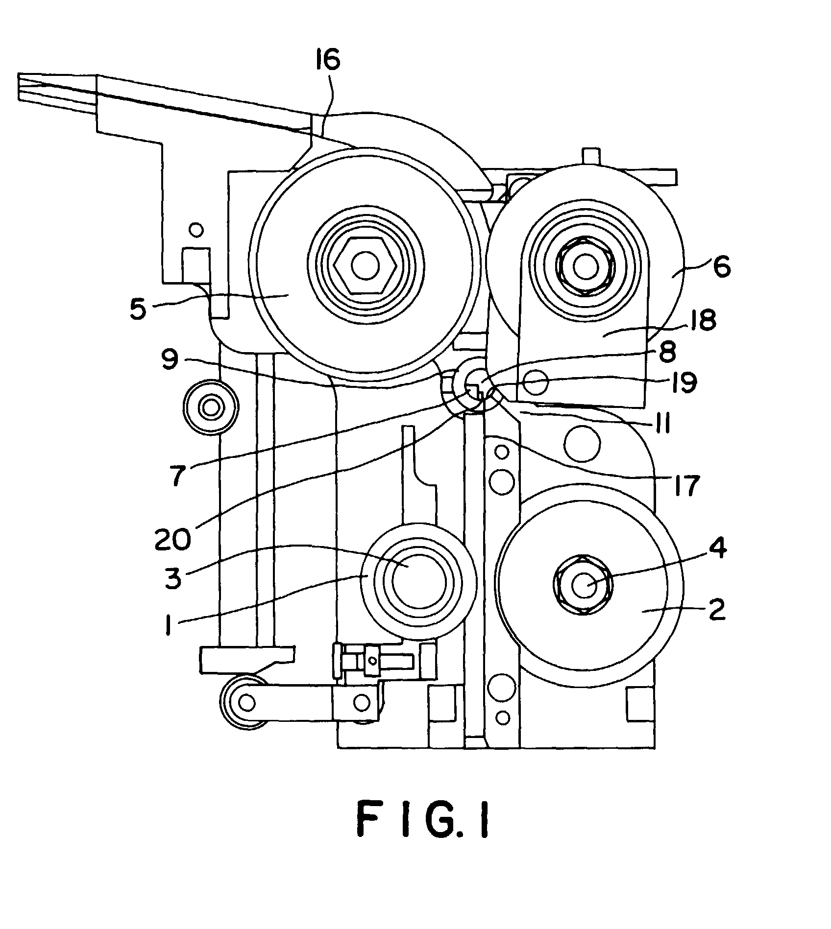
Figure 1 is a front view; and,
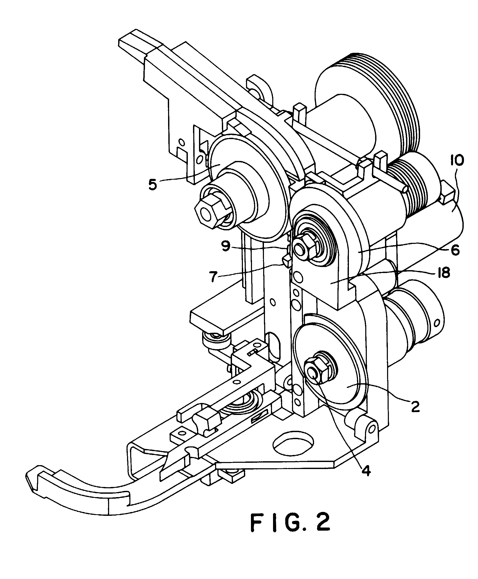
Figure 2 is a top right perspective view.
[0005] Referring to Figure 1, the strap severing and ejecting apparatus of the present invention
provides a strap cutter element 7 located between a first and second tension wheel
set 5, 6, and a first and second feed wheel set 1, 2. The strap cutter element rotates
about a strap cutter axis 8 and may be disposed within a strap cutter sleeve 9. During
normal operation of the strapping machine, the strap passes undisturbed along an edge
of the strap cutter element 7 through normal path 17. However, in the event of a strap
error downstream of the tension wheel, the strap cutter element 7 rotates in a direction
which positions a strap segment between rotating cutting surface 20 of the strap cutter
element 7 and a fixed cutting surface 19. Continued rotation of the strap cutter element
7 severs the strap at that point, and also directs the downstream portion of the severed
strap 16, including the strap error, into an ejection path 11, while at the same time
blocking the normal path 17. A pivotable strap guide 18 may be spring loaded.
[0006] The same first and second tension wheels 5, 6 which are utilized during normal operation
of the strapping device are now operated to withdraw the strap 16 including the strap
error out of the strapping machine for disposal or recycling. A gear motor 10 may
be utilized to rotate the strap cutter element 7 between the normal position and the
cutting/ejection position. A linkage may be provided for use in connection with the
gear motor 10 to limit the angular displacement of the rotating strap cutter element
7.
[0007] After the strap error has been completely rejected from the strapping machine, the
first and second feed wheels refeed the strap through the normal path 17, past the
strap cutter element 7 which has been returned to its normal operation position, and
up through the chute for the next strapping job.
[0008] In this manner, the first and second feed wheels 1, 2, and the first and second tension
wheels 5, 6 serve dual functions, one function during normal strapping conditions,
and a second function during the automatic strap ejection procedure. The dual function
of the feed and tension wheels allows for a simplification and reduction of the function
of the feed and tension wheels allows for a simplification and reduction of the total
elements necessary for the strapping machine to carry out the required functions.
This leads to cost reductions, maintenance simplification, and reliability increases
over prior art strapping machines.
1. A strapping machine comprising:
a strap feeding means (1,2), a strap cutting means (7,9), and a strap tensioning means
(5, 6), the strap cutting means (7,9) being unobtrusive to strap travel during normal
operation, but being operable to sever a strap (16) in the event of a mis-feed, and,
upon servering the strap to direct a downstream section of the severed strap to an
ejection path (11) through which the downstream section of the severed strap is ejected;
characterised in that the strap cutting means (7,9) are disposed along a normal strap
travel path (17) being positioned between the strap feeding means (1,2) and the strap
tensioning means (5,6) and in that the severed strap (16) is ejected by only the strap
tensioning means (5,6).
2. A strapping machine according to claim 1, the strap cutting means (7, 9) being a rotatable
strap cutter element (7), a rotating cutting surface (19) being located along an edge
of the strap cutter element (7), and further comprising a fixed cutting surface (20)
separate from and adjacent to the rotating cutting surface, a strap segment to be
severed being disposed between the rotating cutting surface (19) and the fixed cutting
surface (20), wherein the rotation of the cutter element through a cutting cycle places
the rotating cutting surface (19) against the strap segment (16) to be severed and
then moves the cutting surface (19) through the strap (16) towards the opposing fixed
cutting surface (20) until the strap (16) is severed and then, in this position, directs
the severed strap to the ejection path (11).
3. A strapping machine according to claim 1 or 2, the strap tensioning means being a
first tension wheel (5) and a second tension wheel (6), the strap feeding means being
a first feed wheel (1) and a second feed wheel (2), the strap cutter element (7, 9)
being disposed between the first and second tension wheels (5, 6) and the first and
second feed wheels (1, 2), the first and second tension wheels (5, 6) being rotatable
to withdraw a segment of strap (16) from the strapping machine and deliver the segment
of strap (16) to the ejector path (11) and ultimately out of the strapping machine,
wherein the first and second tension wheels (5, 6) serve the dual function of tensioning
the strap (16) during normal operation and ejection of the strap segment (16) from
the strapping machine in the event of strap error.
4. A strapping machine according to claim 3, further comprising a pivotable strap guide
(18) disposed adjacent the second tension wheel (6), the pivotable strap guide (18)
being pivotable away from the normal strap travel path (17) during a strap error severing
and ejection cycle, wherein rotation of the pivotable strap guide (18) away from the
normal strap travel path opens the ejection path (11) to the strap segment (16) to
be ejected.
5. A strapping machine according to claim 4, wherein the pivotable strap guide (18) is
spring loaded.
6. A strapping machine according to any of the preceding claims, further comprising a
gear motor (10) which rotates the strap cutter element (7) through its range of rotation.
7. A strapping machine according to any of the preceding claims, further comprising a
strap cutter sleeve (9) which houses the strap cutter element (7), the strap cutter
sleeve (9) being stationary.
8. A strapping machine according to any of the preceding claims, wherein the strap is
automatically refed into the strapping machine by strap feeding means (1, 2) after
completion of the strap segment ejection cycle.
1. Umreifungsmaschine, umfassend:
ein Umreifungsmittel-Fördermittel (1, 2), ein Umreifungsmittel-Trennmittel (7, 9)
und ein Umreifungsmittel-Spannmittel (5, 6), wobei das Umreifungsmittel-Trennmittel
(7, 9) während des normalen Betriebes einen Umreifungsmitteltransport nicht beeinträchtigt,
aber welches betätigbar ist, ein Umreifungsmittel (17) im Falle einer Fehlförderung
abzutrennen, und einen stromabwärtigen Abschnitt des abgetrennten Umreifungsmittels
nach dem Abtrennen des Umreifungsmittels zu einem Auswurfpfad (11) zu lenken, durch
den der stromabwärtige Abschnitt des abgetrennten Umreifungsmittels ausgeworfen wird,
dadurch gekennzeichnet, daß das Umreifungsmittel-Trennmittel (7, 9) entlang einem normalen Umreifungsmittel-Transportpfad
(17) angeordnet ist, positioniert zwischen dem Umreifungsmittel-Fördermittel (1, 2)
und dem Umreifungsmittel-Spannmittel (5, 6), und daß das abgetrennte Umreifungsmittel
(16) lediglich durch die Umreifungsmittel-Spannmittel (5, 6) ausgeworfen wird.
2. Umreifungsmaschine nach Anspruch 1, wobei das Umreifungsmittel-Trennmittel (7, 9)
ein drehbares Umreifungsmittel-Trennelement (7) ist, wobei eine rotierende Schneidfläche
(19) entlang einer Kante des Umreifungsmittel-Trennelementes (7) angeordnet ist, und
weiterhin umfassend eine feststehende Schneidfläche (20), die separat von der rotierenden
Schneidfläche und dieser benachbart angeordnet ist, wobei ein abzutrennender Abschnitt
eines Umreifungsmittels zwischen der rotierenden Schneidfläche (19) und der feststehenden
Schneidfläche (20) angeordnet ist, wobei die Rotation des Schneidelements in einem
Trennzyklus die rotierende Schneidfläche (19) gegen den abzutrennenden Umreifungsmittelabschnitt
(16) plaziert und anschließend die Schneidfläche (19) durch das Umreifungsmittel (16)
hindurch zu der gegenüberliegenden feststehenden Schneidfläche (20) hin bewegt, bis
das Umreifungsmittel (16) abgetrennt ist, und anschließend, in dieser Position, das
abgetrennte Umreifungsmittel zu einem Auswurfpfad (11) lenkt.
3. Umreifungsmaschine nach Anspruch 1 oder 2, wobei das Umreifungsmittel-Spannmittel
eine erste Spannrolle (5) und eine zweite Spannrolle (6) ist, wobei das Umreifungsmittel-Fördermittel
eine erste Förderrolle (1) und eine zweite Förderrolle (2) ist, wobei das Umreifungsmittel-Trennelement
(7, 9) zwischen der ersten und der zweiten Spannrolle (5, 6) und der ersten und zweiten
Förderrolle (1, 2) angeordnet ist, wobei die erste und zweite Spannrolle (5, 6) drehbar
sind, um einen Umreifungsmittelabschnitt (16) aus der Umreifungsmaschine herauszuziehen
und den Umreifungsmittelabschnitt (16) zu dem Auswurfpfad (11) zu bringen, sowie letztlich
nach außerhalb der Umreifungsmaschine, wobei die erste und die zweite Spannrolle (5,
6) die zweifache Funktion des Spannens des Umreifungsmittels (16) während des Normalbetriebs
und den Auswurf des Umreifungsmittelabschnittes (16) aus der Umreifungsmaschine im
Falle eines Umreifungsmittelfehlers erfüllen.
4. Umreifungsmaschine nach Anspruch 3, weiterhin umfassend eine schwenkbare Umreifungsmittelführung
(18), die benachbart der zweiten Spannrolle (6) angeordnet ist, wobei die schwenkbare
Umreifungsmittelführung (18) von dem normalen Umreifungsmittel-Transportpfad (17)
während eines Umreifungsmittelfehler-Abtrennund auswurfzyklus wegschwenkbar ist, wobei
die Drehung der schwenkbaren Umreifungsmittelführung (18) von dem normalen Umreifungsmittel-Transportpfad
weg den Auswurfpfad (11) für den auszuwerfenden Umreifungsmittelabschnitt (16) öffnet.
5. Umreifungsmaschine nach Anspruch 4, wobei die schwenkbare Umreifungsmittelführung
(18) federbelastet ist.
6. Umreifungsmaschine nach einem der vorangehenden Ansprüche, weiterhin umfassend einen
Getriebemotor (10), der das Umreifungsmittel-Trennelement (7) durch seinen Drehbereich
hindurch dreht.
7. Umreifungsmaschine nach einem der vorangehenden Ansprüche, weiterhin umfassend eine
Umreifungsmittel-Trennmanschette (9), die das Umreifungsmittel-schneidelement (7)
aufnimmt, wobei die Umreifungsmittel-Trennmanschette (9) stationär ist.
8. Umreifungsmaschine nach einem der vorangehenden Ansprüche, bei der das Umreifungsmittel
automatisch wieder durch Umreifungsmittel-Fördermittel (1, 2) in die Umreifungsmaschine
geführt wird, nachdem der Umreifungsmittelabschnitt-Auswurfzyklus beendet ist.
1. Machine de cerclage comprenant :
un moyen de distribution de bande (1, 2), un moyen de coupe de bande (7, 9), et un
moyen de tension de bande (5, 6), le moyen de coupe de bande (7, 9) ne faisant pas
obstacle au déplacement de bande durant un fonctionnement normal, mais étant adapté
à sectionner une bande (16) en cas de raté de distribution et, lors du sectionnement
de la bande, à diriger une section d'aval de la bande sectionnée jusqu'à un passage
d'éjection (11) via lequel la section d'aval de la bande sectionnée est éjectée ;
caractérisée en ce que le moyen de coupe de bande (7, 9) est disposé le long d'une
trajectoire de bande normale (17), étant positionné entre le moyen de distribution
de bande (1, 2) et le moyen de tension de bande (5, 6) et en ce que la bande sectionnée
(16) est éjectée uniquement par le moyen de tension de bande (5, 6).
2. Machine de cerclage selon la revendication 1, le moyen de coupe de bande (7, 9) consistant
en un élément de couteau de bande rotatif (7), une surface de coupe rotative (19)
étant située le long d'un bord de l'élément de couteau de bande (7), et comprenant,
en outre, une surface de coupe fixe (20) séparée de, et adjacente à, la surface de
coupe rotative, un segment de bande à sectionner étant disposé entre la surface de
coupe rotative (19) et la surface de coupe fixe (20), dans laquelle la rotation de
l'élément de couteau dans un cycle de coupe place la surface de coupe rotative (19)
contre le segment de bande (16) à sectionner puis amène la surface de coupe (19) à
traverser la bande (16) vers la surface de coupe fixe opposée (20) jusqu'à ce que
la bande (16) soit sectionnée puis, dans cette position, dirige la bande sectionnée
jusqu'au passage d'éjection (11).
3. Machine de cerclage selon la revendication 1 ou 2, le moyen de tension de bande consistant
en une première roue de tension (5) et une seconde roue de tension (6), le moyen de
distribution de bande consistant en une première roue de distribution (1) et une seconde
roue de distribution (2), l'élément de couteau de bande (7, 9) étant disposé entre
les première et seconde roues de tension (5, 6) et les première et seconde roues de
distribution (1, 2), les première et seconde roues de tension (5, 6) étant adaptées
à tourner pour extraire un segment de bande (16) de la machine de cerclage et acheminer
le segment de bande (16) jusqu'au passage d'éjection (11) puis enfin hors de la machine
de cerclage, dans laquelle les première et seconde roues de tension (5, 6) ont une
fonction double consistant à tendre la bande (16) durant un fonctionnement normal
et à éjecter le segment de bande (16) de la machine de cerclage en cas de bande ratée.
4. Machine de cerclage selon la revendication 3, comprenant, en outre, un guide de bande
pivotant (18) disposé adjacent à la seconde roue de tension (6), le guide de bande
pivotant (18) étant adapté à pivoter loin de la trajectoire de bande normale (17)
durant un cycle de sectionnement et d'éjection de bande ratée, dans laquelle la rotation
du guide de bande pivotant (18) loin de la trajectoire de bande normale ouvre le passage
d'éjection (11) au segment de bande (16) à éjecter.
5. Machine de cerclage selon la revendication 4, dans laquelle le guide de bande pivotant
(18) est chargé par ressort.
6. Machine de cerclage selon l'une quelconque des revendications précédentes, comprenant,
en outre, un moteur à engrenage (10) qui fait tourner l'élément de couteau de bande
(7) sur toute son étendue de rotation.
7. Machine de cerclage selon l'une quelconque des revendications précédentes, comprenant,
en outre, un manchon de couteau de bande (9) qui loge l'élément de couteau de bande
(7), le manchon de couteau de bande (9) étant fixe.
8. Machine de cerclage selon l'une quelconque des revendications précédentes, dans laquelle
la bande est automatiquement redistribuée dans la machine de cerclage par le moyen
de distribution de bande (1, 2) une fois achevé le cycle d'éjection de segment de
bande.