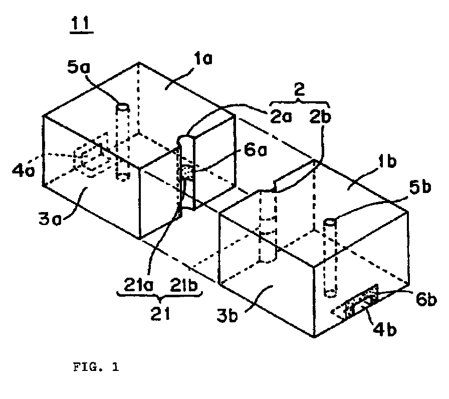
(57) A dielectric filter (11) includes a couple of transverse electric (TE)10-mode resonators
(1a, 1b) connected in series. Each resonator (1a, 1b) is such that a conductor (3a,
3b) is formed on one substantially entire surface of a dielectric body (6a, 6b). On
the connection surfaces of the resonators (1a, 1b) are formed grooves (2a, 2b), respectively.
On the inner round surface of the grooves (2a, 2b), excluding the portions of central
gaps (21a, 21b), there are formed conductors (3a, 3b). Connecting the couple of resonators
(1a, 1b) combines the grooves (2a, 2b) to form a coupling-adjustment hole (2) having
an axis parallel to the interface between the resonators (1a, 1b). The gaps (21a,
21b) combine to form a coupling window (21). The coupling window (21) is exposed in
the coupling-adjustment hole (2), which electromagnetically couples the couple of
resonators (1a, 1b).
|
|
