|
(11) | EP 0 798 829 B1 |

| (12) | EUROPEAN PATENT SPECIFICATION |
|
|
| (54) |
GAS LASER OSCILLATION APPARATUS GASENTLADUNGS-LASEROSZILLATIONSGERÄT OSCILLATEUR LASER A DECHARGE DANS UN GAZ |
|
|
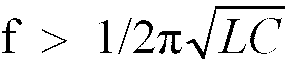
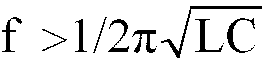
|||||||||||||||||||||||||||||||
| Note: Within nine months from the publication of the mention of the grant of the European patent, any person may give notice to the European Patent Office of opposition to the European patent granted. Notice of opposition shall be filed in a written reasoned statement. It shall not be deemed to have been filed until the opposition fee has been paid. (Art. 99(1) European Patent Convention). |
TECHNICAL FIELD
[0001] The present invention relates to a gas laser oscillator apparatus based on gas discharge excitation.
BACKGROUND ART
[0002] Fig. 4 shows a circuit of a high voltage DC power supply of a conventional gas laser oscillator apparatus.
[0003] In Fig. 4, 1 designates an inverter unit, 2 a boosting transformer, 3 rectifying diodes, 5 a laser tube and 7 a smoothing capacitor.
[0004] The operation of the circuit of the high voltage DC power supply constructed as above will be described hereunder. Firstly, a high frequency voltage is generated by the inverter unit 1 and the high frequency voltage is boosted to a high-frequency high voltage by the boosting transformer 2. Next, the high-frequency high voltage is rectified by the rectifying diodes 3, a high voltage after rectification is smoothed by the smoothing capacitor 7 and a DC high voltage is supplied to the laser tube 5 to discharge and excite a laser gas medium filled in the laser tube 5, thereby producing a laser beam.
[0005] The above conventional construction, however, faced a problem that when the laser beam was operated in a pulse form, discharge current was disturbed.
[0006] Namely, there arose a problem that as shown in Fig. 4, depending on the value of an operating frequency f, a region existed in which the discharge current became unstable, and the laser output became unstable during pulse oscillation at a certain operating frequency f.
[0007] US-A-4 910 747 discloses a gas laser oscillator apparatus according to the preamble of claim 1.
DISCLOSURE OF INVENTION
[0008] The present invention has solved the above conventional problem and its object is to provide a gas laser oscillator apparatus which can produce a stable laser output.
[0009] The gas laser oscillator apparatus of the present invention comprises a power supply unit, rectifying means connected to the power supply unit, a smoothing capacitor connected in parallel with the rectifying means, a choke coil connected in series with the rectifying means, and a laser tube connected in parallel with the smoothing capacitor and connected in series with the choke coil, wherein a smoothing capacitor capacitance C and an inductance L of the choke coil are determined by
[0010] With this construction, even when the capacitance C of the smoothing capacitor is set to
a ripple of a current flowing to the laser tube can be smaller than that in the conventional apparatus and a stable laser output can be obtained.
BRIEF DESCRIPTION OF DRAWINGS
[0011] Fig. 1 is a circuit diagram of a high voltage current power supply of a gas laser oscillator apparatus in an embodiment of the present invention, Fig. 2 is a diagram showing a comparison between changes with time in laser outputs of the gas laser oscillator apparatus of the present invention and the conventional gas laser oscillator apparatus, Fig. 3 is a diagram showing the relation between the smoothing capacitor capacitance and the frequency at which discharge is disturbed, and Fig. 4 is a circuit diagram of the high voltage DC power supply of the conventional gas laser oscillator apparatus.
BEST MODE FOR CARRYING OUT THE INVENTION
[0012] An embodiment of the present invention will be described hereunder with reference to the drawings.
[0013] In Fig. 1, 4 designates a smoothing capacitor having a capacitance C set to
and 6 a choke coil having an inductance L and connected in series with rectifying diodes 3 used as rectifying means and a laser tube 5.
[0015] Firstly, a high frequency voltage is generated by an inverter unit 1 constituting a power supply unit and the high frequency voltage is boosted to a high-frequency high voltage by a boosting transformer 2 also constituting the power supply unit. Next, the high-frequency high voltage is rectified by the rectifying diodes 3.
[0017] Since the smoothing capacitor 4 is set to
a ripple of current increases and a sufficient smoothing degree cannot be obtained but in a countermeasure thereagainst according to the present invention, the ripple of current is decreased by connecting the choke coil 6.
[0018] In Fig. 2, a change with time in laser output of the gas laser oscillator apparatus according to the present embodiment is compared with a change with time in laser output of the conventional gas laser oscillator apparatus. As is clear from Fig. 2, with the gas laser oscillator apparatus according to the present embodiment, beneficial advantages can be obtained from the viewpoint of stability of the laser output.
INDUSTRIAL APPLICABILITY
[0019] As is clear from the foregoing description, according to the present invention, by providing the smoothing capacitor having capacitance C set to
and the choke coil in series with the laser medium, the excellent gas laser oscillator apparatus can be realized which can produce the stable laser output and can realize stable working.
1. A gas laser oscillator apparatus in which a gas laser medium (5) is discharged and
excited by a high voltage DC power supply comprised of an inverter unit (1) for generating
a high frequency voltage, a boosting transformer (2) for boosting said high frequency
voltage, rectifying diodes (3) for rectifying a boosted high-frequency high voltage
and a smoothing capacitor (4) for smoothing a high voltage after rectification, thereby
generating a laser beam in a continuous or pulse form, and an intrinsic inductance
L of said boosting transformer, and a choke coil (6) is connected in series with the
gas laser medium in order to smooth the DC voltage characterised in that said smoothing
capacitor has a smoothing capacitor capacitance C set to
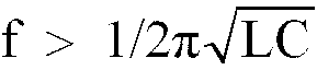
determined by an operating frequency f at which the laser beam is operated in the pulse form.
determined by an operating frequency f at which the laser beam is operated in the pulse form.
1. Eine Oszillatorvorrichtung für einen Gaslaser, in welchem ein Gaslasermedium (5) entladen
und durch eine Hochspannungsgleichstromquelle angeregt wird, welche eine Invertereinheit
(1) zum Erzeugen einer Hochfrequenzspannung, einen Verstärkungstransformator (2) zum
Verstärken der Hochfrequenzspannung, Gleichrichterdioden (3) zum Gleichrichten einer
verstärkten hochfrequenten Hochspannung und einen Glättungskondensator (4) zum Glätten
einer Hochspannung nach Gleichrichtung, wodurch ein Laserstrahl in kontinuierlicher
oder gepulster Form erzeugt wird, und eine intrinsische Induktivität L des Verstärkungstransformators
aufweist, und eine Drosselspule (6) in Reihe mit dem Medium des Gaslasers zum Glätten
der Gleichstromspannung verbunden ist, dadurch gekennzeichnet, daß der Glättungskondensator
eine Glättungskondensatorkapazität C von
besitzt, bestimmt durch eine Betriebsfrequenz f, mit welcher der Laserstrahl in gepulster Form betrieben wird.
besitzt, bestimmt durch eine Betriebsfrequenz f, mit welcher der Laserstrahl in gepulster Form betrieben wird.
1. Un oscillateur laser à décharge dans un gaz dans lequel un milieu laser gazeux (5)
est soumis à une décharge et à une excitation sous l'effet d'une alimentation de puissance
en courant continu à haute tension, constituée d'une unité inverseuse (1) devant générer
une tension à haute fréquence, d'un transformateur suceur (2) pour augmenter ladite
tension à haute fréquence, des diodes de redressement (3) pour redresser une haute
tension à haute fréquence amplifiée et un condensateur de lissage (4) pour lisser
une haute tension après redressement, de manière à générer un faisceau laser ayant
une forme continue ou pulsatoire, et une inductance intrinsèque L dudit transformateur
suceur; et une bobine d'arrêt (6) est branchée en série avec le milieu laser gazeux,
afin de lisser la tension de courant continu, caractérisé en ce que ledit condensateur
de lissage a une capacité électrique de lissage (C) telle que
déterminée par une fréquence de fonctionnement f, à laquelle le faisceau laser est produit sous la forme pulsatoire.
déterminée par une fréquence de fonctionnement f, à laquelle le faisceau laser est produit sous la forme pulsatoire.