| (19) |
 |
|
(11) |
EP 0 704 066 B1 |
| (12) |
EUROPEAN PATENT SPECIFICATION |
| (45) |
Mention of the grant of the patent: |
|
17.10.2001 Bulletin 2001/42 |
| (22) |
Date of filing: 25.05.1994 |
|
| (86) |
International application number: |
|
PCT/AU9400/279 |
| (87) |
International publication number: |
|
WO 9428/444 (08.12.1994 Gazette 1994/27) |
|
| (54) |
MULTIPLE IMAGE DIFFRACTIVE DEVICE
DIFFRAKTIONSVORRICHTUNG MIT MEHREREN ABBILDUNGEN
DISPOSITIF DIFFRACTEUR A IMAGES MULTIPLES
|
| (84) |
Designated Contracting States: |
|
CH DE FR GB LI |
| (30) |
Priority: |
25.05.1993 AU PL900093
|
| (43) |
Date of publication of application: |
|
03.04.1996 Bulletin 1996/14 |
| (73) |
Proprietor: COMMONWEALTH SCIENTIFIC AND INDUSTRIAL RESEARCH ORGANISATION |
|
Campbell,
ACT 2612 (AU) |
|
| (72) |
Inventor: |
|
- LEE, Robert, Arthur
East Burwood, VIC 3125 (AU)
|
| (74) |
Representative: Ertl, Nicholas Justin et al |
|
Elkington and Fife,
Prospect House,
8 Pembroke Road
Sevenoaks,
Kent TN13 1XR
Sevenoaks,
Kent TN13 1XR (GB) |
| (56) |
References cited: :
EP-A- 0 240 261
EP-A- 0 467 601
AU-A- 1 909 692
AU-A- 3 739 093
AU-A- 5 372 990
FR-A- 2 515 396
|
EP-A- 0 240 262
AU-A- 1 049 992
AU-A- 1 957 683
AU-A- 4 811 090
AU-A- 6 282 890
|
|
| |
|
|
- PATENT ABSTRACTS OF JAPAN, P-1057, page 1; & JP,A,2 072 320 (TOPPAN PRINTING CO. LTD),
12 March 1990.
|
|
| |
|
| Note: Within nine months from the publication of the mention of the grant of the European
patent, any person may give notice to the European Patent Office of opposition to
the European patent
granted. Notice of opposition shall be filed in a written reasoned statement. It shall
not be deemed to
have been filed until the opposition fee has been paid. (Art. 99(1) European Patent
Convention).
|
Field of the Invention
[0001] This invention relates to diffractive devices and to their manufacture and has particular
though not exclusive application to the provision of optically variable security diffractive
devices which may be adapted for affixment to or incorporation in, for example, currency
notes, credit cards, charge cards, share certificates and the like.
Background Art
[0002] The present applicant's international patent publication WO91/03747 (application
PCT/AU90/00395) proposes a diffraction grating structure comprised of a multiplicity
of pixels which are individual optical diffraction gratings so that the pixellated
diffraction grating when illuminated generates an optically variable image. The applicant's
pixellated diffraction gratings utilising curved line grating pixels have become known
by the trademark Pixelgram (trade mark). According to preferred aspects of the arrangement
disclosed in the international application, the respective diffraction grating of
each grating pixel comprises a plurality of reflective or transmissive grooves or
lines which are usually curved across a pixel. Groove or line curvature determines
both local image intensity, e.g. shading, and local optical structural stability.
Groove or line spacing in each pixel determines local colour properties, with non-primary
colours generated by a pixel mixing. Average groove or line orientation determines
movement or colour effects, and the number of distinct values of average curvature
and average spacing may be viewed as defining the Pixelgram palette, by analogy with
the language of computer graphics. A further disclosure of a security diffraction
grating structure is to be found in international patent publication WO90/07133 (PCT/AU89/00542).
[0003] The present applicant's international patent publication WO93/18419 (PCT/AU93/00102)
discloses how selected visually observable effects in the optically variable image
may be generated by arraying the pixels in groups within which the pixels are arranged
according to a predetermined rule for the pixellated diffraction grating. Thus, for
example, multiple sets of different images, or of the same image but different shading
or colour, may be produced at different viewing angles.
[0004] The concept of providing multiple optically variable images at different viewing
angles, using a pixellated diffractive device in which each pixel contains a sub-pixel
corresponding to each image, is also disclosed in US patent 5,032,003. In that case,
each diffractive sub-pixel is a straight line grating. This is an example of a more
general class of pixellated diffractive structures utilising straight line grating
pixels and known by the trademark Kinegram.
[0005] Australian patent application 10499/92 proposes a pixellated diffraction grating
structure with three channels which constitute views from different angles of the
same image, in order to obtain a stereoscopic image. The gratings may be curved line
gratings. A predecessor of this reference is Japanese patent (Kokai) publication 2-72320.
[0006] European patent publication 467601 is concerned with holographic diffraction grating
patterns which may include curved line gratings. Overlaid or alternate channels are
proposed for providing different images at different angles. The different images
may include numerical information and logos.
Summary of the Invention
[0007] The present inventor has now appreciated that the concepts of the aforementioned
applications can be further extended to provide diffractive devices which give one
or more optically variable images, by fracturing the pixels of each image into sub-pixels
and then rearranging and interlacing the sub-pixels so that the sub-pixels cooperatively
provide elements of the respective images. In proposing this further development,
the inventor has appreciated that he can take advantage of the mathematical theorem
in Fourier analysis that the Fourier transform of any diffractive function is translationally
invariant.
[0008] According to a first aspect of the present invention there is provided a pixellated
diffraction device according to claim 1.
[0009] The invention also provides, in another aspect, a method of designing a multi-component
pixellated diffractive device according to claim 19.
[0010] In some prior references, the term "relief structure" is utilised interchangeably
with or instead of "diffraction grating" or "diffraction surface structure". The term
"diffraction surface structure" is employed herein to indicate a structure which is
either reflective or transmissive. Without in any way limiting the scope of "diffraction
surface structures", it is noted that such structures may include, for example, line
or groove diffraction gratings, small squares, rectangles or polygons.
[0011] By "at least a representation" is meant that the respective integer may be actually
formed, or, if not, at least a representation is formed. The representation may be
a set of code or data defining the respective integer, e.g. in a computer memory means.
The designing steps are preferably carried out in suitably programmed computer operations.
The method may advantageously include the step of utilising the derived representation
to drive a suitable machine, e.g. an electron beam lithography machine, to form the
actual diffractive device.
[0012] Preferably, there are at least two optically variable images, each associated with
a respective group of diffractive elements. The images may be the same or similar
scenes but differently oriented or of different shading or colour. One or more further
groups of sub-pixels of the device may collectively generate an optically invariable
image.
[0013] There are preferably at least four sub-pixels per pixel, but more preferably at least
16 in a 4 x 4 square array of square sub-pixels. The pixels are preferably sufficiently
small to be below the resolution limit of a healthy human eye, for example, less than
125 micron on edge and more preferably about 30 to 80, e.g. around 60 micron.
[0014] The diffractive sub-elements are preferably dispersed within each pixel so as to
produce a predetermined discernible effect in the corresponding optically variable
image. The dispersal of the diffractive elements may be chosen from a predetermined
set of selections which therefore defines a mapping palette for the diffractive element
array, again by analogy with the language of computer graphics. In a case where, in
accordance with international patent publication WO91/03747, the respective diffraction
surface structures forming the pixels of the pixellated diffraction surface structure
have been formed, e.g. in relation to predetermined variables such as groove or line
curvature, groove or line spacing and average groove or line orientation, from a primary
palette, the aforementioned mapping palette forms a secondary palette and the diffractive
device entails successive selections from both the primary and secondary palettes.
[0015] The diffractive elements within the pixels may involve classes of miniature diffraction
gratings of curved and variably spaced grooves, or alternatively elementary arrays
of polygon shaped relief structures (pixels within pixels of pixels or SQUOTS) of
dimensions of the order of fractions of a micron. In general the transformed representations
of the input images may involve classes of groups of diffractive elements. A class
of different groups of diffractive elements is defined as a component palette of component
pixel types. Since each element of a component palette is itself a group of diffractive
elements, each diffractive element can be regarded as a member of a sub palette and
hence each component palette is, in this embodiment, a palette of sub palettes (palettes
within palettes).
[0016] The invention therefore also provides, in a further aspect, a method of forming a
pixellated diffractive device in terms of a multiplicity of diffraction grating pixel
palettes characterised in that each pixel palette contains diffraction grating groups
and each group M is in itself a sub-pixel palette of N sub-pixel diffractive elements,
comprising defining the device by repeating the diffractive elements of each group
M at predetermined locations within an array of multiple repeat group locations, the
map of repeat group locations for the diffractive elements of each group M being determined
by a set of complex mapping relations between said array and a set of invariable image
component maps which act co-operatively under the control of the mapping relations
to define the diffractive properties of the diffractive device thereby formed on said
array, which diffractive properties cause a multi-component optical effect which is
an observable modification of the individual component pixel optical effects generated
by each of said sub-pixel diffractive elements.
[0017] As already indicated, the images generated by the diffractive device may be either
optically invariable or optically variable. An image is described herein as "optically
variable" where it varies according to the position of observation and "optically
invariable" where it remains substantially the same regardless of the position of
observation. By "image" in the context of this specification is meant the optical
image observed by the naked eye focussed on the diffractive device when it is illuminated
by an arbitrarily extended diffuse source of finite width such as a fluorescent tube.
The term "image" is used herein in its broadest sense, not being limited to pictorial
or diagrammatic images but extending, e.g. to figures, numbers, data and codes.
[0018] It is an advantage of the present invention that the diffractive device may produce
not only a mix of optically variable and optically invariable images but may also
produce two or more different kinds of optically variable images. For example, the
optical variable images may be of a Pixelgram type (i.e. each pixel is a curved line
diffraction grating), a Kinegram type (i.e. each pixel is a straight line diffraction
grating), or a mathematical hologram. For each case, the structure of the component
mapping palettes is determined by the optical properties of the input images and the
required optical properties of the component viewable images generated by the diffractive
device.
[0019] The diffraction device may be provided on a suitable substrate, eg a metal foil,
and/or may be affixed or formed in a carrier eg a currency note, credit card, bank
account or ATM card, debit card, security card, charge card or prepaid card.
Brief Description of the Drawings
[0020] The invention will now be further described, by way of example only, with reference
to the accompanying diagrams, in which:
Figure 1 is a diagrammatic representation of the formation of an embodiment of diffractive
device in accordance with the invention, the diffractive device generating two different
optically variable images and utilising Pixelgram-type curved line diffraction gratings;
and
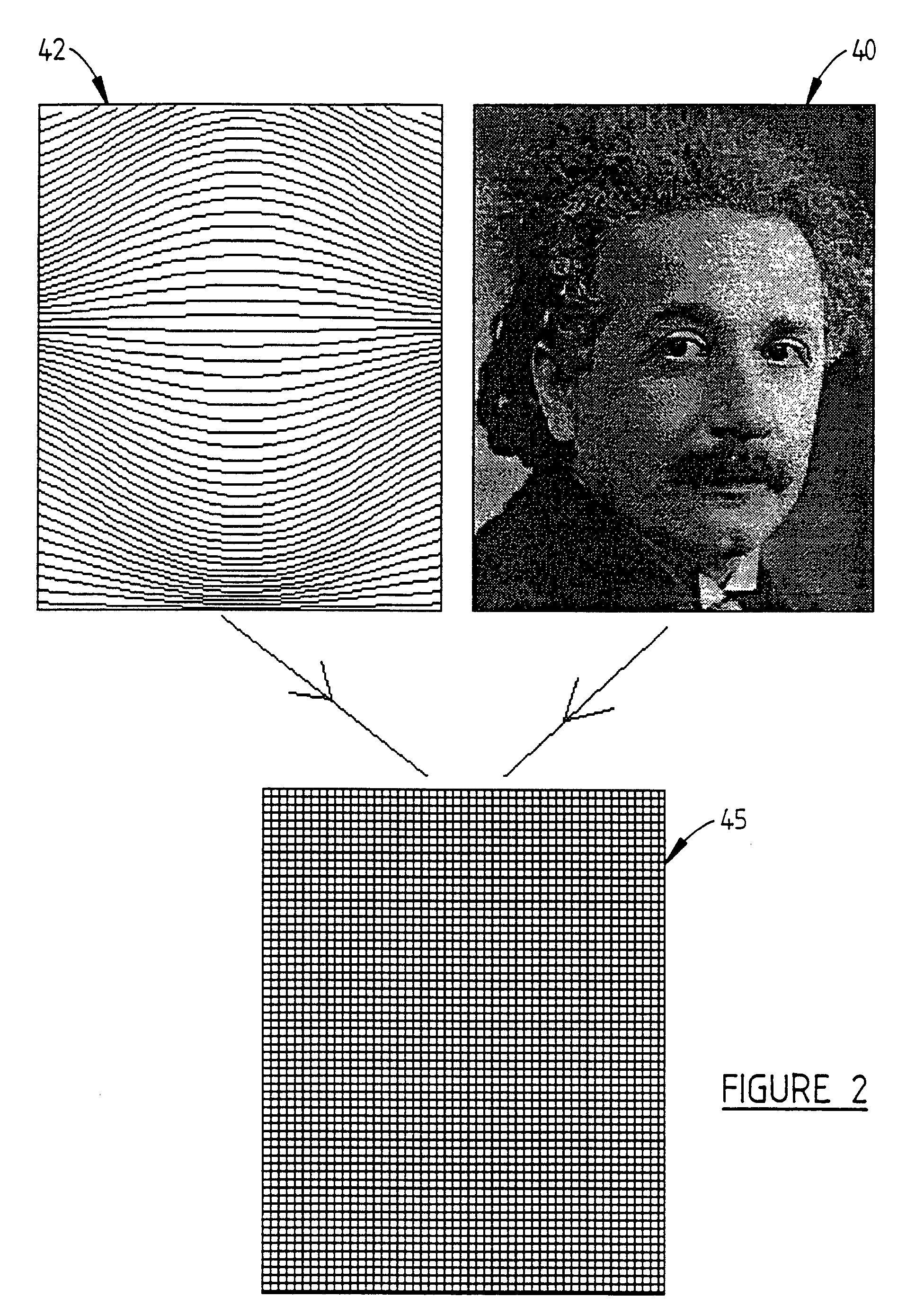
Figure 2 is a diagrammatic representation of a further embodiment of the invention;
and
In Figures 1 and 2, the optical effect arising from slight discontinuities or steps
in the grating lines is a printer artefact.
Description of Preferred Embodiments
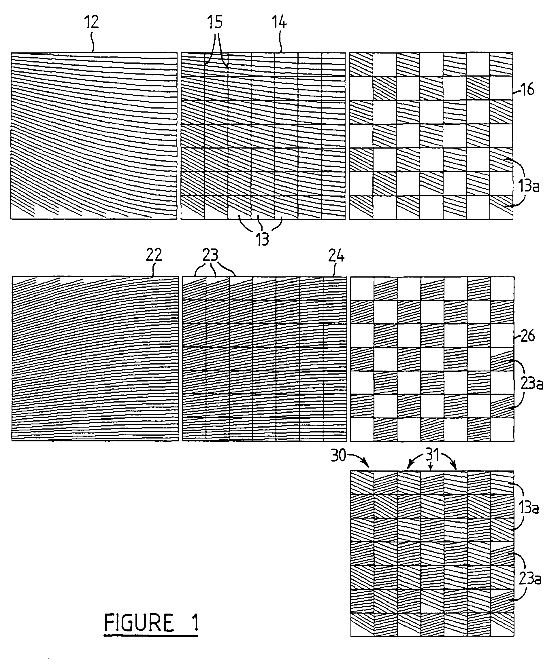
[0021] Figure 1 depicts one pixel 12,22, for each of two pixellated diffraction gratings
designed in accordance with the principles set out in international patent publication
WO91/03747 and intended to produce respective different optically variable images
when illuminated. The two pixels are preferably at corresponding coordinate positions
in the respective gratings. It will be understood that each of the diffraction gratings
does not necessarily physically exist at this stage and that each of the two illustrated
pixels may merely have been designed in a computer system and this design set down
as a representation in the form of a set of stored data, or more preferably as a code
for a selection from a Pixelgram palette, as further discussed hereinafter.
[0022] As explained in international patent publication WO91/03747, the contents of which
are incorporated herein by reference, the respective pixellated diffraction gratings
are produced from an optically invariable image by first dividing up the image into
square pixels (in this case 62.5 micron squares) and assessing the greyness factor,
chroma or colour value, or more specifically the greyness factor, chroma or colour
value of each pixel in turn. This process is typically carried out by exposing an
image to a video camera coupled to a suitable computer system, the greyness factor
for each pixel being stored in the computer memory. Groove or line curvature across
a pixel determines both local image intensity, e.g. shading and local optical structural
stability. Groove or line spacing in each pixel determines local colour properties,
with non-primary colours generated by a pixel mixing. Average groove or line orientation
determines movement and colour effects, and the number of distinct values of average
curvature and average spacing may be viewed as defining the pixelgram palette by analogy
with the language of computer graphics. The lines are derived from a function S
ij(x,y) as more fully explained in international patent publication WO91/03747.
[0023] It is emphasised that the diffraction grating pixels 12,22 may be pixels of other
forms of pixellated diffraction surface structure, e.g. Kinegram-type structures or
holograms.
[0024] The next step is to fracture or divide the respective pixels 12,22 into multiple
diffractive elements 13,23. A preferred fracturing is a simple n x n square array,
depicted in Figure 1 as a grid overlay 15. In this example, it is a 7 x 7 array 14,24
of square diffractive elements 13,23 of almost 9 micron sides, a total of 49 diffractive
elements.
[0025] The set of diffractive elements is then sampled and displaced or rearranged so that
approximately half of the diffractive elements of each set are rearranged in an even,
spaced out array 16,26. It will be seen that the two arrays 16,26 are preselected
so that, in each array, the retained diffractive elements 13a,23a occupy mutually
exclusive positions. The two arrays can then be merged or interlaced to produce the
combined pixel 30 in which the diffractive elements 13a,23a define a complete set
of sub-pixels 31. In this simple case, sub-pixels 31 consist of diffractive elements
13a,23a.
[0026] This process may then be repeated for all the corresponding pixels of the two designed
Pixelgram-type gratings. The resultant set of pixel representations, in the form of
suitable data or code, is applied to an electron beam (or "E-beam") lithography system
to produce the real grating. E-beam machines are particularly suitable for etching
out a diffraction grating microgroove pattern in a substrate in accordance with the
supplied data or codes. This aspect of the process is already known and is described,
e.g., in International patent publication WO91/03747. In a practical application,
a master diffractive device designed to generate characteristic images is made by
the above method, and this master is subsequently utilised to produce authorised copies.
The grating may be typically written as an array of square cut reflective grooves
in a metallised surface, for example PMMA electron resist spin coated onto a chrome
coated glass substrate. This substrate may then be processed to produce a gold coated
nickel master. For example, a durable metal master of the optimised grating may be
obtained by vacuum coating the photo-resist master with 2000 angstrom 99.99% gold
and electro-depositing a thick layer of nickel to act as a support. After separating
from the glass master, this gold coated nickel master may be bonded to a brass block
and used as a die for hot pressing of authorised plastic film/foil replica gratings.
[0027] It will be seen from Figure 1 that the design of the arrays 16,26 involves in some
instances a substantial rearrangement of the relative positions of the diffractive
elements within the pixel. Thus, their relative spatial arrangement is substantially
different from their arrangement within original pixels 12,22, in which the diffractive
elements co-operate as a contiguous surface structure. For example, the diffractive
elements are not merely spread out but occupy different co-ordinate positions in the
array. On the one hand, because of the aforementioned theorem of Fourier analysis,
this does not effect the integrity of the combined contribution of the diffractive
elements or sub-pixels to the corresponding single element or pixel of the viewed
optically variable image. On the other hand, observable effects can be produced in
the viewed image by particular relative rearrangements of the diffractive elements
within a pixel. It is also necessary to take account of the loss of half of the diffractive
elements. Thus, for example, it has been realised that in a diffraction grating pixel
such as 12, the closest spaced lines towards the left and towards the bottom control
the positive order components of the image generated when the grating is illuminated,
and the greater spaced region towards the right and top more controls the negative
order components. Thus, if the diffractive elements 13a retained in the array 16 are
chosen more from the region towards the bottom left corner of pixel 12, there will
be a strong positive bias in the contribution to the pixel of the image. A set of
selections of different rules for sampling and displacing the diffractive elements
13,23 of the fractured array 14,24 can be predetermined as a secondary palette for
the system.
[0028] Some examples of other effects able to be produced by respective selections from
the secondary palette include:
(i) An "RGB" palette consisting of red, green and blue sub-palettes which together
act cooperatively to produce a true colour image of the subject at one angle of view.
The red, green and blue sub-palettes have carrier frequencies which differ slightly
from each other, but the same range of greyness factors;
(ii) Transparency effects produced by an optically variable Pixelgram-type image in
one component with a generalised grating as the second component;
(iii) An optically invariable image in one component and an optically variable image
as the second component. The optically invariable image sub-palette consists of a
palette of diffusely scattering pixels of different levels of greyness which produce
a static image in zero-order.
[0029] It will now be understood that the general case combining the primary and secondary
palettes can be viewed as a set of N component palettes with M1 elements in the first
component palette, M2 elements in the second palette ... and MN elements in the Nth
component palette.
[0030] It will be appreciated that the fracturing, sampling/displacement and recombination
steps in accordance with the preferred practice of the invention allow the production
of complex multi-component diffractive devices for which the images have a much smoother
appearance, since the effective image resolution can be increased due to the grid
size being reduced to the size of a 5 to 15 micron diffractive element or sub-pixel
rather than a full, e.g. 60 or so micron, pixeL The effective palette size has also
been increased by the fracturing and sampling technique since it allows for the mixing
in of additional specialised sub-pixels. Finally, fracturing, sampling and recombination
allows for much more flexibility in assigning image element characteristics to the
mathematical properties of the sub-pixels.
[0031] A number of further embodiments are possible within the general concept of the invention.
For example, the sampling process involved in deriving the array 16,26 from the fractured
pixel 14,24 may involve choosing only (nxn/2)-M diffraction elements from each pixel
and then interlacing 2M sub-pixels not chosen from the main fractured pixels, with
specialised optical properties, to fill the remaining areas of the eventual array.
These additional sub-pixels may be designed to contribute special diffuse light effects,
zero order diffraction effects or applications-specific colour switch effects to the
final image.
[0032] In another alternative embodiment (Figure 2), also indicated as secondary palette
(ii) above, a Pixelgram-type pixellated diffraction grating 40, shown here as generating
an optically variable image recognisable as Albert Einstein, may be combined with
a non-pixellated generalised diffraction grating 42 consisting of a curved groove
pattern with variable spacings between the grooves. The result is a diffractive device
45 which under illumination produces one or more optically variable semi-transparent
images embedded in a background diffractive field. Because the background generalised
grating is relatively slowly varying when compared to the very small scale pixellated
grating pattern, the background grating pattern will produce relatively large scale
zero-order Talbot or Moire fringe patterns when the diffractive device is copied using
holographic reflection contact printing techniques. The presence of the strong fringe
pattern on the copy will ensure that the copy is markedly different from the original
version and hence this type of diffractive device in accordance with an embodiment
of the invention will have a high level of optical security.
[0033] It will be appreciated that in each of these embodiments, each of a group M of miniature
diffraction grating groups is repeated at predetermined locations within a large array
of repeat group locations. The map of these locations for each group M is determined
by set of complex mapping relations between the large array and a set of invariable
image component maps which act co-operatively under the control of the mapping relations
to define the diffractive properties of the diffractive device thereby formed on said
large array. The mapping relation required to produce the type of diffractive device
described in the preceding paragraph is similar to that required for the device illustrated
in Figure 1 except that the generalised grating pattern first needs to be redefined
mathematically as a set of n x m small grating elements that can be interpreted as
grating pixels able to be combined with the n x m pixels of the input Pixelgram-type
component. This redefinition of the generalised grating can be achieved by overlying
the grating with an imaginary n x m grid and then calculating the average groove spacing
and azimuth angle or groove orientation within each grid element or pixel. The generalised
grating then becomes a set of n x m conventional straight line grating pixels of different
orientations which can be fractured, sampled, displaced and interlaced with corresponding
sub-pixels of the corresponding Pixelgram type grating pixels.
[0034] Throughout this specification and the claims which follows, unless the context requires
otherwise, the word "comprise", or variations such as "comprises" or "comprising",
will be understood to imply the inclusion of a stated integer or group of integers
but not the exclusion of any other integer or group of integers.
1. A pixellated diffraction grating providing an optically variable image, wherein each
pixel (30) of the grating comprises an array of sub-pixels (31) in the form of diffractive
elements (13a, 23a), wherein the diffractive elements (13a,23a) of each pixel (30)
comprise at least first (13a) and second (23a) groups of diffractive elements, the
first group of diffractive elements (13a) from each pixel (12) together defining a
diffraction grating for a first image, and the second group of diffractive elements
(23a) from each pixel (22) together defining a diffraction grating for a second image,
wherein the groups of diffractive elements (13a, 23a) occupy mutually exclusive positions
within each pixel, and wherein the first and second groups of diffractive elements
(13a, 23a) cooperatively contribute to the image of each pixel (30) of the grating
and wherein the diffractive elements (13a,23a) have a size of 5 to 15 microns.
2. A grating according to claim 1, characterised in that first and second images are both optically variable.
3. A pixellated diffraction device according to any preceding claim, characterised in that said sub-pixels are so dispersed within each pixel that their relative spatial arrangement
is substantially different from their arrangement within said corresponding single
pixel, in which the sub-pixels co-operate as a contiguous surface structure.
4. A pixellated diffractive device according to claim 2 or 3, characterised in that said optically variable images are the same or similar scenes, but differently orientated
or of different shading or colour.
5. A pixellated diffractive device according to any preceding claim, characterised in that one or more further groups of sub-pixels of the device co-operatively generate an
optically invariable image on illumination of the device.
6. A pixellated diffractive device according to claim 5, further including one or more
groups of diffusely scattering sub-pixels which produce an optically invariable image
on illumination.
7. A pixellated diffraction device according to any preceding claim, characterised in that there are at least 16 sub-pixels per pixel in a 4x4 array of square sub-pixels.
8. A pixellated diffraction device according to any preceding claim, characterised in that said pixels are less than 125 microns square.
9. A pixellated diffractive device according to any preceding claim, characterised in that said sub-pixels comprise respective miniature diffraction gratings of curved and
variably spaced grooves.
10. A pixellated diffractive device according to any preceding claim, characterised in that said sub-pixels comprise polygon shaped relief structures of dimensions of the order
of fractions of a micron.
11. A pixellated diffractive device according to claim 1, comprising at least three sub-pixel
groups, each group including diffractive elements of a single colour, such that the
three groups co-operate to produce a true colour image at a particular angle of view.
12. A pixellated diffractive device according to claim 11, characterised in that the respective colours of the three groups are. red, green and blue.
13. A pixellated diffractive device according to any preceding claim, characterised in that each pixel of the device contains two interlaced sub-pixel groups, one group corresponding
to a sub-division of a pixel of a pixellated diffractive surface structure in which
the pixel grating lines are curved, and the other group corresponding to subdivisions
of elementary grid areas of a generalised diffraction grating of curved and variable
spaced lines, and further characterised in that observed images generated by the diffractive device under any particular light source
have the appearance of a generalised diffraction grating of curved and variably spaced
lines, such that observed images generated by the diffractive device have the appearance
of a generalised diffraction grating pattern seen through a transparent or semi-transparent
diffraction image generated by said diffraction surface structure in which the pixel
grating lines are curved.
14. A pixellated diffractive device according to claim 13, characterised in that 5 the generalised diffraction grating pattern is a relatively slowly varying groove
pattern such that any attempted copying of the diffractive device, using the method
of holographic contact copying, results in a copied image with overlaid relatively
large scale Talbot or Moire fringe effects, not present on the original diffractive
device.
15. A pixellated diffractive device according to any preceding claim, characterised in that said groups of sub-pixels produce an optically variable image on illumination.
16. A pixellated diffraction device according to any preceding claim, characterised in that each pixel of the device contains two interlaced sub-pixel groups, one of which corresponds
to the sub-division of the pixels of a first pixellated diffraction surface structure
in which the pixel grating lines are curved, and the other of which corresponds to
the subdivision of the pixels of a second pixellated diffraction surface structure
in which the pixel grating lines are straight, further characterised in that observed images generated by the diffractive device under an illuminating light source
have optical characteristics of both said first and second diffractive surface structures.
17. A pixellated diffraction device according to any preceding claim, characterised in that each pixel of the device contains two interlaced sub-pixel groups, one of which corresponds
to the sub-division of the pixels of a primary pixellated diffraction surface structure
in which the pixel grating lines are curved, and the other of which corresponds to
the pixel subdivision of a diffusely scattering image device containing multiple levels
of greyscale information, such that observed images, generated by the diffraction
device, under an illuminating light source, contain both optically variable image
information of the primary pixellated diffractive surface structure as well as zero
order optically invariable information of the diffusely scattering image device, and
further characterised in that the zero order optically invariable image information contains similar levels of
greyscale information as said levels present in the original diffusely scattering
image device.
18. A pixellated diffraction device according to any preceding claim, characterised in that the individual diffractive elements making up each sub-pixel are spatially located
in said gridded array at locations in said array which are spatially distant from
their respective locations within said corresponding pixel.
19. A method of designing a multi-component pixellated diffractive device comprised of
a multiplicity of diffractive pixels (30) which are each divided into sub-pixels,
which method comprises:
(a) designing two or more pixellated diffractive surface structures which, when illuminated,
generate respective images.
(b) subdividing each pixel (12,22) of each said primary structure into plural diffractive
elements (13,23) having a size of 5 to 15 microns, and
(c) designing the multi-component pixellated diffractive device as a secondary a multi-component
pixellated diffractive device by defining each pixel (30) thereof as a plurality of
sub-pixel groups (13a,23a), each sub-pixel group being composed of a first group of
diffractive elements (13a) of a spatially corresponding pixel of a first primary pixellated
diffractive surface structure intermixed in a gridded array with a second group of
diffractive elements (23a) of a spatially corresponding pixel of a second primary
pixellated diffractive surface structure, the first and second groups of diffractive
elements (13a,23a) cooperatively contributing to the image of each pixel (30) of the
multi-component device.
20. A method as claimed in claim 19, wherein the primary structures generate optically
variable images.
21. A method according to claim 19 or 20, further including utilising the derived secondary
design to drive a machine, to form the actual diffractive device.
22. A method according to claim 21, characterised in that said machine is an electron beam lithography machine.
23. A method according to any one of claims 19 to 22, characterised in that said sub-pixels of the secondary design are so dispersed within each pixel that their
relative spatial arrangement is substantially different from their arrangement within
said corresponding single pixel, in which the sub-pixels co-operate as a contiguous
surface structure.
24. A method according to claim 20, characterised in that said optically variable images are the same or similar scenes but differently orientated
or of different shading or colour.
25. A method according to any one of claims 19 to 24, characterised in that there are at least 16 said sub-pixels in a 4x4 array of square sub-pixels.
26. A method according to claim 25, characterised in that said pixels are less than 125 microns square.
27. A method according to any one of claims 19 to 26, characterised in that said sub-pixels comprise respective miniature diffraction gratings of curved and
variably spaced grooves.
28. A method according to any one of claims 19 to 27, characterised in that said sub-pixels comprise polygon shaped relief structures of dimensions of the order
of fractions of a micron.
29. A method according to any one of claims 19 to 28, characterised in that said secondary design is such that the respective groups include diffractive elements
of three single colours and these groups co-operate to produce a true colour image
at a particular angle of view.
30. A method according to claim 29, characterised in that there are respective colour groups for red, green and blue.
31. A method as claimed in claim 19, wherein said diffractive device is formed from a
multiplicity of diffraction grating pixel palettes characterised in that each pixel. palette contains diffraction grating groups and each group M is in itself
a sub-pixel palette of N sub-pixel diffractive elements, comprising defining the device
by repeating the diffractive elements of each group M at predetermined locations within
an array of multiple repeat group locations, the map of repeat group locations for
the diffractive elements of each group M being determined by a set of complex mapping
relations between said array and a set of invariable image component maps which act
co-operatively under the control of the mapping relations to define the diffractive
properties of the diffractive device thereby formed on said array, which diffractive
properties cause said multi-component optical effect.
32. A pixellated diffraction device formed by the method of any one of claims 19 to 31.
33. A stored set of data defining a pixellated diffractive device according to any one
of claims 1 to 18.
34. A computer program product which stores machine readable instructions which, when
installed in a computer with an appropriate operating system and memory, carry out
the method of any one of claims 19-31.
1. Pixeldiffraktionsgitter für ein optisch variables Bild, worin jedes Pixel (30) des
Gitters eine Anordnung von Subpixeln (31) in Form von Diffraktionselementen (13a,
23a) umfasst, worin die Diffraktionselemente (13a, 23a) jedes Pixels (30) mindestens
erste (13a) und zweite (23a) Gruppen von Diffraktionselementen umfassen, wobei die
erste Gruppe von Diffraktionselementen (13a) von jedem Pixel (12) zusammen ein Diffraktionsgitter
für ein erstes Bild definieren und die zweite Gruppe von Diffraktionselementen (23a)
von jedem Pixel (22) zusammen ein Diffraktionsgitter für ein zweites Bild definieren,
worin die Gruppen von Diffraktionselementen (13a, 23a) einander ausschliessende Positionen
in jedem Pixel besetzen, und worin die ersten und zweiten Gruppen von Diffraktionselementen
(13a, 23a) kooperativ zum Bild jedes Pixels (30) des Gitters beitragen und worin die
Diffraktionselemente (13a, 23a) eine Grösse von 5 bis 15 Mikrometern aufweisen.
2. Gitter nach Anspruch 1, dadurch gekennzeichnet, dass sowohl erste wie zweite Bilder optisch variabel sind.
3. Pixeldiffraktionsvorrichtung nach einem der vorhergehenden Ansprüche, dadurch gekennzeichnet, dass die Subpixel so in jedem Pixel dispergiert sind, dass ihre relative räumliche Anordnung
sich im wesentlichen von ihrer Anordnung im entsprechenden Einzelpixel unterscheidet,
in dem die Subpixel als zusammenhängende Oberflächenstruktur kooperieren.
4. Pixeldiffraktionsvorrichtung nach Anspruch 2 oder 3, dadurch gekennzeichnet, dass die optisch variablen Bilder gleiche oder ähnliche Szenen sind, die aber unterschiedlich
orientiert sind oder unterschiedliche Schattierung oder Farbe aufweisen.
5. Pixeldiffraktionsvorrichtung nach einem der vorhergehenden Ansprüche, dadurch gekennzeichnet, dass eine oder mehrere weitere Gruppen von Subpixeln der Vorrichtung bei Beleuchtung der
Vorrichtung kooperativ ein optisch invariables Bild erzeugen.
6. Pixeldiffraktionsvorrichtung nach Anspruch 5, ferner umfassend eine oder mehrere Gruppen
von diffus streuenden Subpixeln, die bei Beleuchtung ein optisch invariables Bild
produzieren.
7. Pixeldiffraktionsvorrichtung nach einem der vorhergehenden Ansprüche, dadurch gekennzeichnet, dass mindestens 16 Subpixel pro Pixel in einer 4x4-Anordnung von quadratischen Subpixeln
vorhanden sind.
8. Pixeldiffraktionsvorrichtung nach einem der vorhergehenden Ansprüche, dadurch gekennzeichnet, dass die Pixel weniger als 125 Mikrometer im Quadrat aufweisen.
9. Pixeldiffraktionsvorrichtung nach einem der vorhergehenden Ansprüche, dadurch gekennzeichnet, dass die Subpixel entsprechende Miniaturdiffraktionsgitter mit geschwungenen und variabel
beabstandeten Rillen umfassen.
10. Pixeldiffraktionsvorrichtung nach einem der vorhergehenden Ansprüche, dadurch gekennzeichnet, dass die Subpixel polygonförmige Reliefstrukturen mit Abmessungen in der Grössenordnung
von Mikrometerbruchteilen umfassen.
11. Pixeldiffraktionsvorrichtung nach Anspruch 1, umfassend mindestens drei Subpixelgruppen,
wobei jede Gruppe Diffraktionselemente einer einzigen Farbe aufweist, derart, dass
die drei Gruppen kooperieren, um in einem bestimmten Blickwinkel ein echtfarbiges
Bild zu produzieren.
12. Pixeldiffraktionsvorrichtung nach Anspruch 11, dadurch gekennzeichnet, dass die entsprechenden Farben in den drei Gruppen Rot, Grün und Blau sind.
13. Pixeldiffraktionsvorrichtung nach einem der vorhergehenden Ansprüche, dadurch gekennzeichnet, dass jedes Pixel der Vorrichtung zwei verknüpfte Subpixelgruppen enthält, wobei eine Gruppe
einer Subdivision eines Pixels einer Pixeldiffraktionsoberflächenstruktur entspricht,
in der die Pixelgitterlinien geschwungen sind, und die andere Gruppe Subdivisionen
von Elementargitterrasterbereichen eines allgemeinen Diffraktionsgitters von geschwungenen
und variabel beabstandeten Linien entspricht, und ferner dadurch gekennzeichnet, dass durch die Diffraktionsvorrichtung erzeugte unter einer bestimmten Lichtquelle sichtbare
Bilder das Aussehen eines allgemeinen Diffraktionsgitters von geschwungenen und variabel
beabstandeten Linien aufweist, derart, dass durch die Diffraktionsvorrichtung erzeugte
sichtbare Bilder das Aussehen eines allgemeinen Diffraktionsgittermusters aufweist,
gesehen durch ein transparentes oder halbtransparentes Diffraktionsbild erzeugt durch
die Diffraktionsoberflächenstruktur, in der die Pixelgitterlinien geschwungen sind.
14. Pixeldiffraktionsvorrichtung nach Anspruch 13, dadurch gekennzeichnet, dass das allgemeine Diffraktionsgittermuster ein relativ langsam sich veränderndes Rillenmuster
ist, derart, dass ein versuchtes Kopieren der Diffraktionsvorrichtung, unter Verwendung
des holographischen Kontaktkopierverfahrens, zu einem kopierten Bild mit überlagerten
relativ grossen Talbot- oder Moire-Effekten ist, die in der Originaldiffraktionsvorrichtung
nicht vorhanden sind.
15. Pixeldiffraktionsvorrichtung nach einem der vorhergehenden Ansprüche, dadurch gekennzeichnet, dass die Subpixelgruppen bei Beleuchtung ein optisch variables Bild produzieren.
16. Pixeldiffraktionsvorrichtung nach einem der vorhergehenden Ansprüche, dadurch gekennzeichnet, dass jedes Pixel der Vorrichtung zwei verknüpfte Subpixelgruppen enthält, deren eine der
Subdivision der Pixel einer ersten Pixeldiffraktionsoberflächenstruktur entspricht,
in der die Pixelgitterlinien geschwungen sind, und deren andere der Subdivision der
Pixel einer zweiten Pixeldiffraktionsoberflächenstruktur entspricht, in der die Pixellinien
gerade sind, ferner dadurch gekennzeichnet, dass die unter einer Beleuchtungslichtquelle durch die Diffraktionsvorrichtung erzeugten
sichtbaren Bilder optische Eigenschaften sowohl der ersten wie der zweiten Diffraktionsoberflächenstrukturen
aufweisen.
17. Pixeldiffraktionsvorrichtung nach einem der vorhergehenden Ansprüche, dadurch gekennzeichnet, dass jedes Pixel der Vorrichtung zwei verknüpfte Subpixelgruppen enthält, deren eine der
Subdivision der Pixel einer primären Pixeldiffraktionsoberflächenstruktur entspricht,
in der die Pixelgitterlinien geschwungen sind, und deren andere der Pixelsubdivision
einer diffus streuenden Bildvorrichtung entspricht, die zahlreiche Stufen der Grauskaleninformation
enthält, derart, dass von der Diffraktionsvorrichtung unter einer Beleuchtungslichtquelle
erzeugte sichtbare Bilder sowohl optisch variable Bildinformation der primären Pixeldiffraktionsoberflächenstruktur
als auch optisch invariable Information nullter Ordnung der diffus streuenden Bildvorrichtung
enthalten, und ferner dadurch gekennzeichnet, dass die optisch invariable Bildinformation der nullten Ordnung ähnliche Stufen der Grauskaleninformation
enthält wie die in der diffus streuenden Originalbildvorrichtung vorhandenen Stufen.
18. Pixeldiffraktionsvorrichtung nach einem der vorhergehenden Ansprüche, dadurch gekennzeichnet, dass die einzelnen Diffraktionselemente, die jedes Subpixel bilden, räumlich in der Gitterrasteranordnung
an Orten angeordnet sind, die räumlich von ihren entsprechenden Orten im entsprechenden
Pixel fern sind.
19. Verfahren zur Konstruktion einer Mehrkomponenten-Pixeldiffraktionsvorrichtung gebildet
aus einer Vielzahl von Diffraktionspixeln (30), die jedes in Subpixel unterteilt sind,
wobei das Verfahren umfasst:
(a) Konstruieren von zwei oder mehr Pixeldiffraktionsoberflächenstrukturen, die beim
Beleuchten entsprechende Bilder erzeugen,
(b) Unterteilen jedes Pixels (12, 22) jeder der primären Strukturen in viele Diffraktionselemente
(13, 23) mit einer Grösse von 5 bis 15 Mikrometern, und
(c) Konstruieren der Mehrkomponenten-Pixeldiffraktionsvorrichtung als sekundäre Multikomponenten-Pixeldiffraktionsvorrichtung
durch Definieren jedes Pixels (30) darin als eine Vielzahl von Subpixelgruppen (13a,
23a), wobei jede Subpixelgruppe gebildet ist aus einer ersten Gruppe von Diffraktionselementen
(13a) eines räumlich entsprechenden Pixels einer ersten primären Pixeldiffraktionsoberflächenstruktur
vermischt in einer Gitterrasteranordnung mit einer zweiten Gruppe von Diffraktionselementen
(23a) eines räumlich entsprechenden Pixels einer zweiten primären Pixeldiffraktionsoberflächenstruktur,
wobei die erste und zweite Gruppe von Diffraktionselementen (13a, 23a) kooperativ
zum Bild jedes Pixels (30) der Multikomponentenvorrichtung beitragen.
20. Verfahren nach Anspruch 19, worin die primären Strukturen optisch variable Bilder
erzeugen.
21. Verfahren nach Anspruch 19 oder 20, ferner umfassend die Nutzung der gewonnenen zweiten
Konstruktion zum Betrieb einer Maschine, um die tatsächliche Diffraktionsvorrichtung
auszubilden.
22. Verfahren nach Anspruch 21, dadurch gekennzeichnet, dass die Maschine eine Elektronenstrahllithographiemaschine ist.
23. Verfahren nach einem der Ansprüche 19 bis 22, dadurch gekennzeichnet, dass die Subpixel der zweiten Konstruktion so in jedem Pixel dispergiert sind, dass ihre
relative räumliche Anordnung sich im wesentlichen von ihrer Anordnung im entsprechenden
Einzelpixel unterscheidet, in dem die Subpixel als zusammenhängende Oberflächenstruktur
kooperieren.
24. Verfahren nach Anspruch 20, dadurch gekennzeichnet, dass die optisch variablen Bilder gleiche oder ähnliche Szenen aufweisen, aber unterschiedlich
orientiert oder in unterschiedlicher Schattierung oder Farbe.
25. Verfahren nach einem der Ansprüche 19 bis 24, dadurch gekennzeichnet, dass mindestens 16 Subpixel in einer 4x4-Anordnung von quadratischen Subpixeln vorhanden
sind.
26. Verfahren nach Anspruch 25, dadurch gekennzeichnet, dass die Pixel weniger als 125 Mikrometer im Quadrat aufweisen.
27. Verfahren nach einem der Ansprüche 19 bis 26, dadurch gekennzeichnet, dass die Subpixel entsprechende Miniaturdiffraktionsgitter aus geschwungenen und variabel
beabstandeten Rillen umfassen.
28. Verfahren nach einem der Ansprüche 19 bis 27, dadurch gekennzeichnet, dass die Subpixel polygonförmige Reliefstrukturen mit Abmessungen in der Grössenordnung
von Mikrometerbruchteilen umfassen.
29. Verfahren nach einem der Ansprüche 19 bis 28, dadurch gekennzeichnet, dass die sekundäre Konstruktion derart ist, dass die entsprechenden Gruppen Diffraktionselemente
von drei einzelnen Farben aufweisen und diese Gruppen kooperieren, um bei einem bestimmten
Blickwinkel ein echtfarbiges Bild zu produzieren.
30. Verfahren nach Anspruch 29, dadurch gekennzeichnet, dass entsprechende Farbgruppen für Rot, Grün und Blau vorhanden sind.
31. Verfahren nach Anspruch 19, worin die Diffraktionsvorrichtung aus einer Vielzahl von
Diffraktionsgitterpixelpaletten gebildet wird, dadurch gekennzeichnet, dass jede Pixelpalette Diffraktionsgittergruppen enthält und jede Gruppe M in sich eine
Subpixelpalette von N Subpixeldiffraktionselementen ist, umfassend Definieren der
Vorrichtung durch Wiederholen der Diffraktionselemente jeder Gruppe M an bestimmten
Orten in einer Anordnung von zahlreichen Wiederholungsgruppenorten, wobei das Raster
der Wiederholungsgruppenorte für die Diffraktionselemente jeder Gruppe M durch einen
Satz komplexer Rasterbeziehungen zwischen der Anordnung und einem Satz invariabler
Bildkomponentenraster bestimmt wird, die kooperativ unter dem Einfluss der Rasterbeziehungen
wirken, um die Diffraktionseigenschaften der dadurch auf der Anordnung ausgebildeten
Diffraktionsvorrichtung zu definieren, welche Diffraktionseigenschaften den mehrkomponentigen
optischen Effekt bewirken.
32. Pixeldiffraktionsvorrichtung gebildet durch das Verfahren nach einem der Ansprüche
19 bis 31.
33. Gespeicherter Datensatz, der eine Pixeldiffraktionsvorrichtung nach einem der Ansprüche
1 bis 18 definiert.
34. Computerprogrammprodukt, das maschinenlesbare Instruktionen speichert, die, wenn sie
in einem Computer mit einem geeigneten Betriebssystem und Speicher installiert sind,
das Verfahren nach einem der Ansprüche 19 bis 31 ausführen.
1. Réseau de diffraction pixellisé fournissant une image optiquement variable, dans lequel
chaque pixel (30) du réseau comprend un ensemble de sous-pixels (31) sous la forme
d'éléments diffractifs (13a, 23a), dans lequel les éléments diffractifs (13a, 23a)
de chaque pixel (30) comprennent au moins un premier groupe (13a) et un deuxième groupe
(23a) d'éléments diffractifs, le premier groupe d'éléments diffractifs (13a) de chaque
pixel (12) définissant ensemble un réseau de diffraction pour une première image,
et le deuxième groupe d'éléments diffractifs (23a) de chaque pixel (22) définissant
ensemble un réseau de diffraction pour une deuxième image, dans lequel les groupes
d'éléments diffractifs (13a, 23a) occupent des positions mutuellement exclusives dans
chaque pixel, et dans lequel les premier et deuxième groupes d'éléments diffractifs
(13a, 23a) contribuent de manière coopérative à l'image de chaque pixel (30) du réseau
et dans lequel les éléments diffractifs (13a, 23a) ont une taille de 5 à 15 microns.
2. Réseau selon la revendication 1 caractérisé en ce que ces première et deuxième images sont toutes les deux optiquement variables.
3. Dispositif diffracteur pixellisé selon une quelconque des revendications précédentes,
caractérisé en ce que lesdits sous-pixels sont dispersés dans chaque pixel de telle manière que leur disposition
spatiale relative est substantiellement différente de leur disposition dans ledit
seul pixel correspondant dans lequel les sous-pixels coopèrent comme une structure
de surface contiguë.
4. Dispositif diffracteur pixellisé selon la revendication 2 ou 3, caractérisé en ce que lesdites images optiquement variables sont les mêmes scènes ou des scènes similaires
mais orientées différemment ou d'une teinte ou couleur différente.
5. Dispositif diffracteur pixellisé selon une quelconque des revendications précédentes,
caractérisé en ce que un ou plusieurs autres groupes de sous-pixels du dispositif génèrent de manière coopérative
une image optiquement invariable lors de l'éclairage du dispositif.
6. Dispositif diffracteur pixellisé selon la revendication 5 comprenant en outre un ou
plusieurs groupes de sous-pixels se dispersant de manière diffuse qui produisent une
image optiquement invariable lors de l'éclairage.
7. Dispositif diffracteur pixellisé selon une quelconque des revendications précédentes,
caractérisé en ce qu'il y a au moins 16 sous-pixels par pixel dans un ensemble de sous-pixels carrés de
4 X 4.
8. Dispositif diffracteur pixellisé selon une quelconque des revendications précédentes,
caractérisé en ce que lesdits pixels font moins de 125 microns carrés.
9. Dispositif diffracteur pixellisé selon une quelconque des revendications précédentes,
caractérisé en ce que lesdits sous-pixels comprennent des réseaux de diffraction miniatures respectifs
de raies courbes et espacées de manière variable.
10. Dispositif diffracteur pixellisé selon une quelconque des revendications précédentes,
caractérisé en ce que lesdits sous-pixels comprennent des structures en relief en forme de polygone de
dimensions de l'ordre de fractions d'un micron.
11. Dispositif diffracteur pixellisé selon la revendication 1 comprenant au moins trois
groupes de sous-pixels, chaque groupe incluant des éléments diffractifs d'une seule
couleur, de sorte que les trois groupes coopèrent pour produire une véritable image
en couleur sous un angle de vue particulier.
12. Dispositif diffracteur pixellisé selon la revendication 11, caractérisé en ce que les couleurs respectives des trois groupes sont le rouge, le vert et le bleu.
13. Dispositif diffracteur pixellisé selon une quelconque des revendications précédentes,
caractérisé en ce que chaque pixel du dispositif contient deux groupes de sous-pixels entrelacés, un groupe
correspondant à une subdivision d'un pixel d'une structure de surface de diffraction
pixellisée dans laquelle les lignes du réseau de pixels sont courbes et l'autre groupe
correspondant à des subdivisions de régions élémentaires d'un réseau de diffraction
généralisé de lignes courbes et espacées de manière variable, et caractérisé en outre en ce que les images observées générées par le dispositif diffracteur sous une quelconque source
lumineuse particulière ont l'apparence d'un réseau de diffraction généralisé de lignes
courbes et espacées de manière variable, de sorte que les images observées générées
par le dispositif diffracteur ont l'apparence d'une configuration de réseau de diffraction
généralisé vu au travers d'une image diffractée transparente ou semitransparente générée
par ladite structure de surface de diffraction dans laquelle les lignes du réseau
de pixels sont courbes.
14. Dispositif diffracteur pixellisé selon la revendication 13, caractérisé en ce que la configuration du réseau de diffraction généralisé est une configuration de raies
variant relativement lentement de sorte que toute tentative de copiage du dispositif
diffracteur, en utilisant la méthode de copiage holographique par contact, a pour
résultat une image copiée avec des effets superposés de franges moirées ou de Talbot
à relativement grande échelle qui ne sont pas présents sur le dispositif diffracteur
original.
15. Dispositif diffracteur pixellisé selon une quelconque des revendications précédentes,
caractérisé en ce que lesdits groupes de sous-pixels produisent une image optiquement variable lors de
l'éclairage.
16. Dispositif diffracteur pixellisé selon une quelconque des revendications précédentes,
caractérisé en ce que chaque pixel du dispositif contient deux groupes de sous-pixels entrelacés, dont
l'un correspond à la subdivision des pixels d'une première structure de surface de
diffraction pixellisée dans laquelle les lignes du réseau de pixels sont courbes et
dont l'autre correspond à la subdivision des pixels d'une deuxième structure de surface
de diffraction pixellisée dans laquelle les lignes du réseau de pixels sont droites,
caractérisé en outre en ce que les images observées générées par le dispositif diffracteur sous une source lumineuse
d'éclairage ont des caractéristiques optiques desdites première et deuxième structures
de surface de diffraction pixellisée.
17. Dispositif diffracteur pixellisé selon une quelconque des revendications précédentes,
caractérisé en ce que chaque pixel du dispositif contient deux groupes de sous-pixels entrelacés, dont
l'un correspond à la subdivision des pixels d'une structure de surface de diffraction
pixellisée primaire dans laquelle les lignes du réseau de pixels sont courbes et dont
l'autre correspond à la subdivision des pixels d'un dispositif d'images à dispersion
diffuse contenant de multiples niveaux d'information sur l'échelle des gris, de sorte
que des images observées, générées par le dispositif diffracteur, sous une source
lumineuse d'éclairage, contient des informations sur les images optiquement variables
de la structure de surface de diffraction pixellisée primaire ainsi que des informations
optiquement invariables d'ordre zéro du dispositif d'images à dispersion diffuse,
et caractérisé en outre en ce que les informations sur les images optiquement invariables d'ordre zéro contiennent
des niveaux similaires d'information sur l'échelle des gris que lesdits niveaux présents
dans le dispositif d'images à dispersion diffuse original.
18. Dispositif diffracteur pixellisé selon une quelconque des revendications précédentes,
caractérisé en ce que les éléments diffractifs individuels constituant chaque sous-pixel sont situés spatialement
dans ledit ensemble réticulaire à des emplacements dans ledit ensemble qui sont spatialement
distants de leurs emplacements respectifs dans lesdits pixels correspondants.
19. Procédé pour concevoir un dispositif diffracteur pixellisé à composants multiples
constitué d'une multiplicité de pixels diffractifs (30) qui sont chacun divisé en
sous-pixels, laquelle méthode consiste:
(a) à concevoir deux ou plusieurs structures de surface de diffraction pixellisée
qui, quand elles sont éclairées, génèrent des images respectives,
(b) à subdiviser chaque pixel (12, 22) de chaque dite structure primaire en plusieurs
éléments diffractifs (13, 23) ayant une taille de 5 à 15 microns, et
(c) à concevoir le dispositif diffracteur pixellisé à composants multiples comme un
dispositif diffracteur pixellisé secondaire à composants multiples en définissant
chaque pixel (30) de celui-ci comme une pluralité de groupes (43a, 23a) de sous-pixels,
chaque groupe de sous-pixels étant composé d'un premier groupe d'éléments diffractifs
(13a) d'un pixel spatialement correspondant d'une première structure de surface de
diffraction pixellisée primaire mélangé dans un ensemble réticulaire avec un deuxième
groupe d'éléments diffractifs (23a) d'un pixel spatialement correspondant d'une deuxième
structure de surface de diffraction pixellisée primaire, les premier et deuxième groupes
d'éléments diffractifs (13a, 23a) contribuant de manière coopérative à l'image de
chaque pixel (30) du dispositif à composants multiples.
20. Procédé selon la revendication 19, dans lequel les structures primaires génèrent des
images optiquement variables.
21. Procédé selon la revendication 19 ou 20 comprenant en outre l'utilisation de la conception
secondaire dérivée pour piloter une machine pour former le dispositif diffracteur
effectif.
22. Procédé selon la revendication 21, caractérisé en ce que ladite machine est une machine de lithographie à faisceaux d'électrons.
23. Procédé selon une quelconque des revendications 19 à 22, caractérisé en ce que lesdits sous-pixels de la conception secondaire sont dispersés dans chaque pixel
de telle manière que leur disposition spatiale relative est substantiellement différente
de leur disposition dans ledit seul pixel correspondant dans lequel les sous-pixels
coopèrent comme une structure de surface contiguë.
24. Procédé selon la revendication 20, caractérisé en ce que lesdites images optiquement variables sont les mêmes scènes ou des scènes similaires
mais orientées différemment ou d'une teinte ou couleur différente.
25. Procédé selon une quelconque des revendications 19 à 24, caractérisé en ce qu'il y a au moins 16 dits sous-pixels dans un ensemble de sous-pixels carrés de 4 X
4.
26. Procédé selon la revendication 25, caractérisé en ce que lesdits pixels font moins de 125 microns carrés.
27. Procédé selon une quelconque des revendications 19 à 26, caractérisé en ce que lesdits sous-pixels comprennent des réseaux de diffraction miniatures respectifs
de raies courbes et espacées de manière variable.
28. Procédé selon une quelconque des revendications 19 à 27, caractérisé en ce que lesdits sous-pixels comprennent de structures en relief en forme de polygone de dimensions
de l'ordre de fractions d'un micron.
29. Procédé selon une quelconque des revendications 19 à 28, caractérisé en ce que ladite conception secondaire est telle que les groupes respectifs comprennent des
éléments diffractifs de trois couleurs uniques et ces groupes coopèrent pour produire
une véritable image en couleur sous un angle de vue particulier.
30. Procédé selon la revendication 29, caractérisé en ce qu'il y a des groupes de couleur respectifs pour le rouge, le vert et le bleu.
31. Procédé selon la revendication 19 dans lequel ledit dispositif diffracteur est formé
par une multiplicité de palettes de pixels de réseaux de diffraction, caractérisé en ce que chaque palette de pixels contient de groupes de réseaux de diffraction et chaque
groupe M est en soi une palette de sous-pixels de N éléments diffractifs de sous-pixels,
consistant à définir le dispositif en répétant les éléments diffractifs de chaque
groupe M à des emplacements prédéterminés dans un ensemble d'emplacements multiples
de groupes répétés, la carte des emplacements des groupes répétés pour les éléments
diffractifs de chaque groupe M étant déterminée par un jeu de relations cartographiques
complexes entre ledit ensemble et un jeu de cartes de composants d'images invariables
qui coopèrent sous le contrôle des relations cartographiques pour définir les propriétés
de diffraction du dispositif diffracteur ainsi formé sur ledit ensemble, lesquelles
propriétés de diffraction engendrent ledit effet optique à composants multiples.
32. Dispositif diffracteur pixellisé formé par le procédé selon l'une quelconque des revendications
19 à 21.
33. Jeu de données stocké définissant un dispositif diffracteur pixellisé selon une quelconque
des revendications 1 à 18.
34. Programme informatique qui stocke des instructions lisibles par machine et qui, quand
il est installé sur un ordinateur avec un système d'exploitation approprié et une
mémoire appropriée, exécute le procédé selon une quelconque des revendications 19
à 31.