| (19) |
 |
|
(11) |
EP 0 836 969 B1 |
| (12) |
EUROPEAN PATENT SPECIFICATION |
| (45) |
Mention of the grant of the patent: |
|
12.03.2003 Bulletin 2003/11 |
| (22) |
Date of filing: 09.10.1997 |
|
|
| (54) |
Air bag steering wheel with visible spokes
Luftsack aufweisendes Lenkrad mit sichtbaren Speichen
Volant de direction avec module de sac gonflable et rayons visibles.
|
| (84) |
Designated Contracting States: |
|
DE ES FR GB IT SE |
| (30) |
Priority: |
15.10.1996 IT MI962133
|
| (43) |
Date of publication of application: |
|
22.04.1998 Bulletin 1998/17 |
| (73) |
Proprietor: BREED AUTOMOTIVE TECHNOLOGY, INC. |
|
Lakeland,
County of Polk,
Florida (US) |
|
| (72) |
Inventor: |
|
- Cattaneo, Marco
27100 Pavia (IT)
|
| (74) |
Representative: Mittler, Enrico et al |
|
c/o Mittler & C. s.r.l.,
Viale Lombardia, 20
20131 Milano
20131 Milano (IT) |
| (56) |
References cited: :
EP-A- 0 050 309
DE-A- 3 742 125
GB-A- 2 142 299
GB-A- 2 242 871
US-A- 4 167 276
|
DE-A- 3 508 380
GB-A- 1 238 644
GB-A- 2 192 841
US-A- 3 827 715
|
|
| |
|
|
|
|
| |
|
| Note: Within nine months from the publication of the mention of the grant of the European
patent, any person may give notice to the European Patent Office of opposition to
the European patent
granted. Notice of opposition shall be filed in a written reasoned statement. It shall
not be deemed to
have been filed until the opposition fee has been paid. (Art. 99(1) European Patent
Convention).
|
[0001] The present invention consists of a motor vehicle steering wheel equipped with air
bag, that provides for visible spokes aimed at conferring a sports appearance to the
steering wheel itself.
[0002] It is now customary use to supply steering wheels with safety devices of the "air
bag" type, that allow the driver to avoid catastrophic collisions against the steering
wheel and in particular against the steering column, in case of an accident one such
steering wheel can be seen in GB-A-2 242 871.
[0003] On the other hand the presence of an air bag device in the known steering wheels
translates into a total covering of the central portion of the wheel, including the
spokes, with the result of compromising the steering wheel sports character. This
can definitely be disagreeable to the end users to which the steering wheel is addressed.
[0004] Object of the present invention is to implement a motor vehicle steering wheel equipped
with an air bag unit, structured in such a way as to keep part of the spokes in sight
in order to maintain a sports appearance though in observance of the required safety
conditions.
[0005] According to the invention this object has been achieved by means of a motor vehicle
steering wheel as defined in claim 1.
[0006] In this way the presence of the air bag device does not compromise the sports appearance
of the steering wheel, that is fully maintained by the visible spokes extending between
the air bag device and the external handling rim.
[0007] The characteristics of the present invention will be made even more evident by the
following detailed description of some embodiments thereof illustrated as a non-restrictive
example in the attached drawings, where:
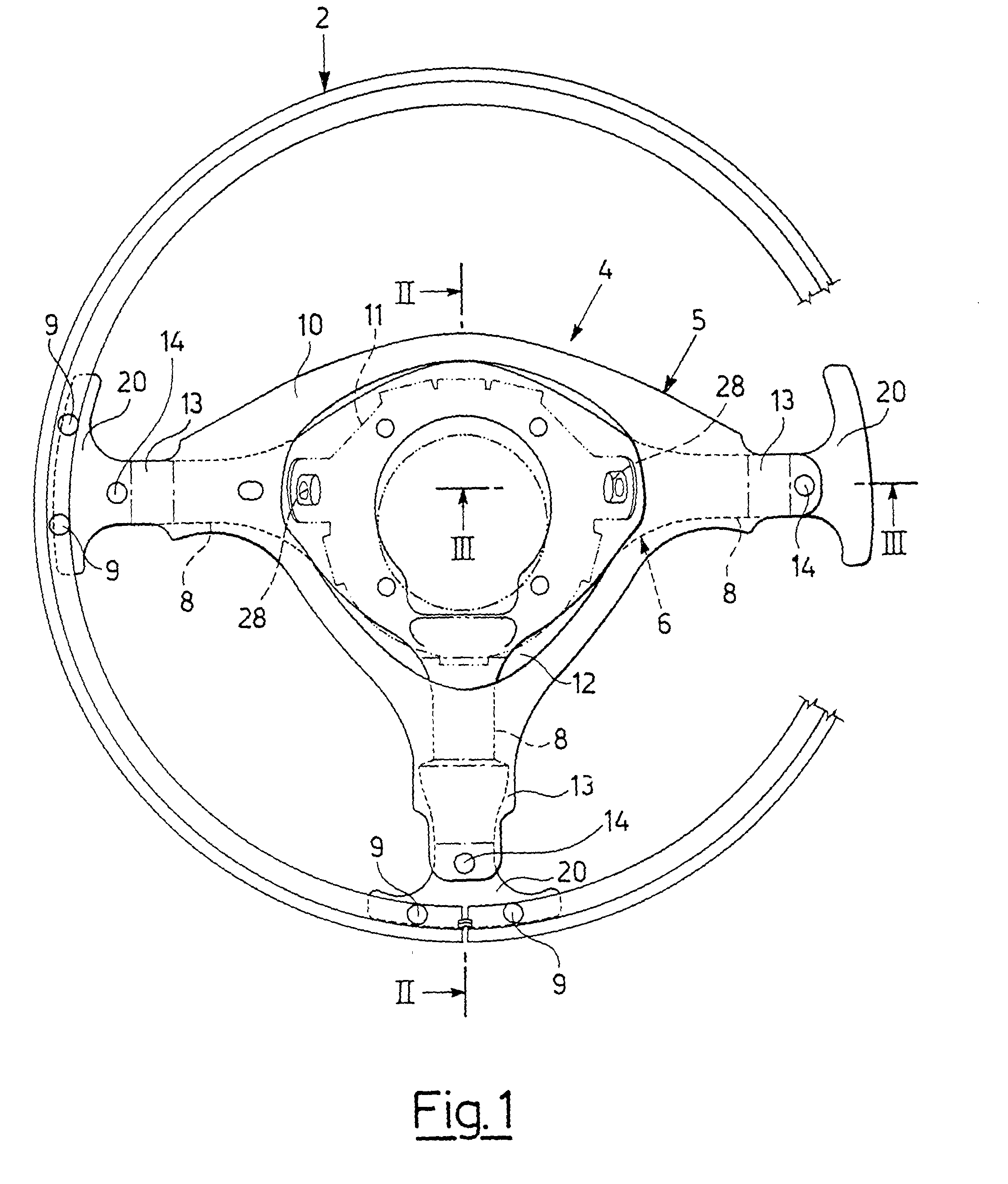
Fig. 1 shows a plan of the steering wheel according to the invention as viewed from
above;
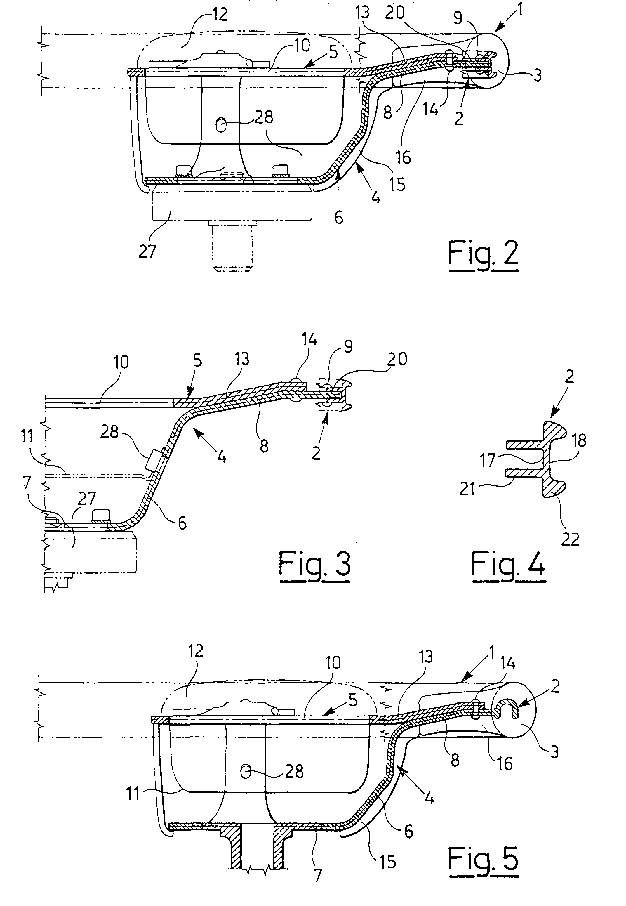
Fig. 2 shows a section of said steering wheel along the line II-II of Fig. 1;
Fig. 3 shows a section of said steering wheel along the line III-III of Fig. 1;
Fig. 4 shows a cross section, enlarged in scale, of the handling rim inner metal core
of the steering wheel of Figures 1-3;
Fig. 5 shows a section view analogous to that of Fig. 2, referring to a variation
of the steering wheel in the previous Figures, which is not part of the invention.
[0008] The steering wheel in Figures 1, 2 and 3 includes a round handling rim 1 consisting
of an inner metal core 2 with a constant section and of an external body 3 in wood,
polyurethane at sight, polyurethane with leather or other appropriate coating.
[0009] The steering wheel includes also a central unit 4 made of two overlapping metal parts
5 and 6 fixed one to the other. The lower part 6 is shaped as a bowl with a central
base 7 to be attached to the steering column by means of an end hub 27 and three T-shaped
external ends 20 radial spokes 8, extending radially and upwards to reach the metal
core 2 of the handling rim 1 and to be fastened to it by means of nails or rivets
9, as shown as an example in Figures 1-3; as an alternative, the metal core 2 can
be made out of a bent sheet or even as an extruded shape and subsequently bent.
[0010] As shown more clearly in Fig. 4, the inner metal core 2 of the handling rim 1 consists
of a bent metal structural shape having constant section, that provides for an internal
throat 17 and an external throat 18. The internal throat 17 serves the purpose to
house the T-shape ends 20 of the radial spokes 8 and to this regard it is equipped
with two close parallel flanges 21 having constant section, conferring the internal
throat 17 a relatively reduced width, just greater than the thickness of the radial
spokes 8 T-shape ends 20. The external throat 18 has a greater width and a reduced
thickness and provides for two short side flanges 22 having a thickness increasing
from the outside to the inside serving the purpose to grant transverse strength to
the metal core 2 and therefore to the handling rim 1.
[0011] The upper part 5 of the central unit 4 is itself essentially flat in shape with a
concave central portion 10 designed to accommodate an air bag device schematically
indicated with 11, housed inside the concavity of the lower part 6 and fastened to
it by means of bolts 28 and covered with a covering element 12 supported by said central
concave portion 10. From the latter, portions of the spokes 13 extend laterally overlapped
and fastened by means of nails or rivets 14 to an inside portion of the radial spokes
8 of the lower part 6.
[0012] The invention finally provides for a lower covering 15 with a coating 16 extending
from the handling rim 1.
[0013] The result is a steering wheel with air bag, that provides for visible metal spokes
aimed at conferring a sports appearance to the steering wheel itself.
[0014] The variation in Fig. 5 shows the same structure characteristics of the steering
wheel in Figures 1-3, with the exception of the base of the lower part 6 of the central
unit 4, designed for direct attachment to the steering column, and of the rim 1 metal
core 2, consisting in a reversed U-section made of a casting with said lower part
6.
1. Motor vehicle steering wheel including an external handling rim (1) and a central
unit (4) with air bag device that has radial spokes extending outwards and attached
to said handling rim, said central unit (4) being made of two parts (5, 6), of which
a lower one (6) shaped as a bowl serving the purpose to accommodate the air bag device
(11) and to be attached to the steering column and comprising radial spokes (8) and
an upper one (5) essentially flat which serves the purpose to support a covering element
(12) for the air bag device and is provided with radial spokes (13) extending from
the sides of said covering element (12) and overlapped and fixed to an inside portion
of said radial spokes (8) of the lower part (6), characterised in that said radial spokes (8) of said lower part (6) are provided with integral T-shaped
ends (20) housed and fixed in an internal throat (17) of a metal core (2) of the handling
rim (1) and said zadial spokes (13) of the upper part (5) extend along the radial
spokes (8) of the lower part (6) to the proximity of the handling rim (1).
2. Steering wheel according to claim 1, characterised in that said metal core (2) of the handling rim (1) is made of an extruded shape bent and
attached to said radial spokes (8).
3. Steering wheel according to claim 1, characterised in that said metal core (2) of the handling rim (1) is made of a bent metal sheet.
4. Steering wheel according to claim 1, characterised in that said internal throat (17) of said metal core (2) of the handling rim (1) has two
parallel flanges (21) which provide the internal throat (17) with a width just greater
than the thickness of the T-shaped ends (20) of the radial spokes (8) of said lower
part (6).
5. Steering wheel according to claim 1, characterised in that said T-shaped ends (20) of the radial spokes (8) of said lower part (6) are directly
attached to the metal core (2) of the handling rim (1).
1. Kraftfahrzeuglenkrad, das einen äußeren Griffkranz (1) und eine Mitteleinheit (4)
mit einer Airbagvorrichtung einschließt, die radiale Speichen hat, die nach außen
verlaufen und an dem Griffkranz angebracht sind, wobei die Mitteleinheit (4) aus zwei
Teilen (5, 6) hergestellt wird, von denen ein unterer (6), wie eine Schüssel geformter,
dazu dient, die Airbagvorrichtung (11) aufzunehmen und an der Lenksäule befestigt
zu werden, und radiale Speichen (8) umfaßt, und ein oberer (5), wesentlich flacher,
dazu dient, ein Abdeckelement (12) für die Airbagvorrichtung zu tragen und mit radialen
Speichen (13) versehen ist, die von den Seiten des Abdeckelements (12) vorstehen und
sich mit einem inneren Abschnitt der radialen Speichen (8) des unteren Teils (6) überschneiden
und an demselben befestigt sind, dadurch gekennzeichnet, daß die radialen Speichen (8) des unteren Teils (6) mit integrierten T-förmigen Enden
(20) versehen sind, die in einer Innenkehle (17) eines Metallkerns (2) des Griffkranzes
(1) eingelassen und befestigt sind, und die radialen Speichen (13) des oberen Teils
(5) längs der radialen Speichen (8) des unteren Teils (6) in die Nähe des Griffkranzes
(1) verlaufen.
2. Lenkrad nach Anspruch 1, dadurch gekennzeichnet, daß der Metallkern (2) des Griffkranzes (1) aus einem gezogenen Profil hergestellt wird,
das gebogen und an den radialen Speichen (8) befestigt wird.
3. Lenkrad nach Anspruch 1, dadurch gekennzeichnet, daß der Metallkern (2) des Criffkranzes (1) aus einer gebogenen Metalltafel hergestellt
wird.
4. Lenkrad nach Anspruch 1, dadurch gekennzeichnet, daß die Innenkehle (17) des Metallkerns (2) des Griffkranzes (1) zwei parallele Flansche
(21) hat, welche die Innenkehle (17) mit einer Breite versehen, die gerade größer
ist als die Stärke der T-förmigen Enden (20) der radialen Speichen (8) des unteren
Teils (6).
5. Lenkrad nach Anspruch 1, dadurch gekennzeichnet, daß die T-förmigen Enden (20) der radialen Speichen (8) des unteren Teils (6) unmittelbar
an dem Metallkern (2) des Griffkranzes (1) befestigt sind.
1. Volant de direction d'un véhicule automobile englobant une jante de manipulation externe
(1) et une unité centrale (4) avec un dispositif de coussin d'air comportant des rayons
radiaux s'étendant vers l'extérieur et fixés à ladite jante de manipulation, ladite
unité centrale (4) étant composée de deux parties (5, 6), la partie inférieure (6)
ayant une forme en bol servant à recevoir le dispositif de coussin d'air (11), destinée
à être fixée sur la colonne de direction et comprenant des rayons radiaux (8), la
partie supérieure (5) étant essentiellement plate et état destinée à supporter un
élément de couverture (12) du dispositif de coussin d'air et comportant elle-même
des rayons radiaux (13) s'étendant à partir des côtés dudit élément de couverture
(12), chevauchant une partie interne desdits rayons radiaux (8) de la partie inférieure
(6) et étant fixés sur celle-ci, caractérisé en ce que lesdits rayons radiaux (8) de ladite partie inférieure (6) comportent des extrémités
en T solidaires (20) reçues dans un étranglement interne (17) d'un noyau métallique
(2) de la jante de manipulation (1) et fixées dans celui-ci, lesdits rayons radiaux
(13) de la partie supérieure (5) s'étendant le long des rayons radiaux (8) de la partie
inférieure (6) à proximité de la jante de manipulation (1).
2. Volant de direction selon la revendication 1, caractérisé en ce que ledit noyau métallique (2) de la jante de manipulation (1) est produit à partir d'une
forme extrudée pliée et fixée auxdits rayons radiaux (8).
3. Volant de direction selon la revendication 1, caractérisé en ce que ledit noyau métallique (2) de la jante de manipulation (1) est composé d'une feuille
métallique pliée.
4. Volant de direction selon la revendication 1, caractérisé en ce que ledit étranglement interne (17) dudit noyau métallique (2) de la jante de manipulation
(1) comporte deux brides parallèles (21) établissant l'étranglement interne (17) ayant
une largeur juste supérieure à l'épaisseur des extrémités en T (20) des rayons radiaux
(8) de ladite partie inférieure (6).
5. Volant de direction selon la revendication 1, caractérisé en ce que lesdites extrémités en T (20) desdits rayons radiaux (8) de ladite partie inférieure
(6) sont fixées directement au noyau métallique (2) de la jante de manipulation (1).