|
(11) | EP 0 683 576 B1 |

| (12) | EUROPEAN PATENT SPECIFICATION |
|
|
| (54) |
An OFDM digital broadcasting system, and a transmission system and a receiving system used for digital broadcasting Digitales OFDM-Rundfunksystem, sowie Übertragungs- und Empfangsvorrichtung für Digitalrundfunk Système de radiodiffusion OFDM numérique, et un système de transmission et un système de réception pour transmissions numériques |
|
|
|||||||||||||||||||||||||||||||||||
| Note: Within nine months from the publication of the mention of the grant of the European patent, any person may give notice to the European Patent Office of opposition to the European patent granted. Notice of opposition shall be filed in a written reasoned statement. It shall not be deemed to have been filed until the opposition fee has been paid. (Art. 99(1) European Patent Convention). |
BACKGROUND OF THE INVENTION
[0001] This invention is related to a digital broadcasting system, and a transmission system and a receiving system used for digital broadcasting, especially to a broadcasting system, and a transmission system and a receiving system used for broadcasting suitable for transmitting/receiving audios, images, data, and other information using a modulating system OFDM that uses plural frequencies set orthogonally with each another.
[0002] When information such as audios, images, data, etc. is received on a vehicle from a digital broadcasting system, received waves are often deteriorated, for example, recognized as signal attenuation to be caused by the interference of broadcast waves reflected on buildings. A transmission/receiving system for digital broadcasting to reduce such the deterioration is reported in IEEE Transactions on Consumer Electronics Vol. 35 No. 3 pp. 493 to 503 (August, 1989). In this transmission method, broadcast signals are dispersed in plural broadcast waves whose transmission rate is low.
[0003] The transmission method of the said transmission and receiving system is called the Orthogonal Frequency Division Multiplexing (OFDM). When a symbol is to be transmitted using this OFDM method, a guard interval which is a fraction of one symbol time is put before the symbol to reduce the influence of delayed waves. The time of one symbol to be transmitted actually becomes longer by the length of the guard interval. Hereafter, the original one symbol time in such the method will be referred to as one effective symbol time in this specification, and the time to transmit one symbol actually (one effective symbol time + guard interval) will be referred to as one transmission symbol time.
[0004] In general, in the transmission method to disperse this broadcast signal in plural low transmission rate broadcast waves, at least more than a few tens of frequencies are used. And, those frequencies are set orthogonally with each other so that they may not interfere each another even when the frequency interval is set narrowly.
[0005] If such the characteristics that transmission frequencies are set orthogonally are used, inverse Fourier transformation and Fourier transformation can be used in both transmission and receiving systems to realize the said broadcasting system.
[0006] To restore broadcast signals such as required audios, images, or data in the OFDM system that disperses broadcast signals in plural frequencies to transmit them, the frequency and timing must be synchronized with transmission signals at first.
[0007] Especially, in case of receiving signals on a vehicle, such the synchronization is often shifted, since the receiving status is changed abruptly. Thus, such the synchronization must be adjusted each time a shift is detected.
[0008] When receiving broadcast signals, the receiving frequency channel or program is often changed, and thus such the synchronization must be adjusted immediately each time the receiving frequency channel or program is changed.
[0009] The article by Leonard J. Cimini : "Analysis and Simulation of a Digital Mobile Channel Using Orthogonal Frequency Division Multiplexing" in "IEEE Transactions on Communications", Vol. COM-33. No 7, July 1985, pages 665 -675 describes an OFDM system in which data are corrected by using two pilot signals which are frequency interpolated.
[0010] The published application WO 9210043 A1 describes a receiver for an OFDM-signal in which the frequency of the sampling oscillator and of the intermediary frequency-baseband transposition oscillator is adjusted by using the results of the calculation of the phase variation of two pilot lines. The adjustment method is based on the use of pilot signals in more than one symbol interval.
[0011] It takes a certain degree of time to acquire the synchronization, and if any one of the frequency and timing synchronizations is lost, transmission data cannot be restored. To avoid such the error, therefore, the frequency synchronization and the timing synchronization must be acquired as early as possible.
Summery Of The Invention
[0012] The purpose of this invention is to provide a digital broardcasting system, a transmission system and a receiving system used for digital broadcasting, which can restore broadcast signals by acquiring quick synchronization in the broadcasting system that uses the OFDM method to transmit signals.
[0014] To achieve further the purpose of this invention, for every fixed time period the transmission system transmits the pilot symbol comprising two or more frequencies whose frequency intervals are 4/(NT) or more, and comprizing only the pilot signals, where 1/(NT) is the transmission frequency interval for transmitting symbols other than that of the pilot signals.
[0015] Furthermore, to achieve the purpose of this invention, received signals are multiplied by a window function such as a Hanning function except for proper rectangle ones when Fourier transformation is carried out to estimate the timing and frequency offsets in the said receiving system.
[0016] Furthermore, to achieve the purpose of this invention, hardjudgment(hard decision or slicing) is carried out together with Fourier transformation for received signals to detect and use the difference between the phases of the hard-judgment results and received signals in the said receiving system.
[0017] Furthermore, to achieve the purpose of this invention, Fourier transformation is carried out so that the frequency interval of the output may become 1/4 or under that of the transmission frequencies when the timing and/or frequency synchronization is not acquired, to acquire the timing synchronization and the frequency synchronization.
[0018] Furthermore, to achieve the purpose of this invention, sampling of received signals for which Fourier transformation is to be carried out to acquire the said synchronization is started at a time within the guard interval.
[0019] Furthermore, to achieve the purpose of this invention, the condition of M/L ≥ 4 is satisfied when the sampling time for received signals that are to be Fourier-transformed is 1/L of one effective symbol time and the pilot signal frequency interval is M times that of the transmission frequencies.
[0020] Furthermore, to achieve the purpose of this invention, Fourier transformation is carried out only for fK - (h + 1)/(NT) to fK + (h + 1)/(NT), which is the neighborhood of the pilot frequency fK to acquire or track the timing synchronization or frequency synchronization, or both synchronizations when the maximum frequency offset ΔFm from the transmission pilot signal frequency fk, to be expected in the receiving system is represented as | ΔFm| ≤ (1 + 2h)/(2NT) using a positive integer h. 1/(NT) is the transmission frequency interval, N is the total number of transmission frequencies, and T is the basic timing period assumed respectively in the transmission system.
[0021] Furthermore, to achieve the purpose of this invention, the frequencies f1 and f2 used for the pilot signal are set so that the condition of 1/| τ'| ≥ 2 | f2 - f1| may be satisfied when the maximum value of the timing phase offset to be expected in the receiving system is τ'.
[0022] In the digital broadcasting system that transmits signals using frequencies that are set orthogonally with each another, fast Fourier transformation (FFT) can be carried out to demodulate all the required frequencies. If both frequency and timing are already synchronized, the output of the Fourier transformation can be assumed as the demodulated output of the required frequencies.
[0023] On the other hand, if the synchronizations are not acquired yet, a proper pilot symbol is transmitted. If the frequencies of the transmitted pilot symbol are already known, the offset of those frequencies and the timing offset can be estimated according to the demodulated output of Fourier transformation. And according to these estimated values, the said synchronizations can be corrected.
[0024] The offset can be estimated more accurately by using window functions including the Hanning function except for the rectangles.
[0025] The estimation can be made more accurately if, when a pilot symbol comprising plural frequencies is transmitted, the frequency interval is of four or more frequencies used for the output of Fourier transformation. Therefore, if the frequency interval used for the Fourier transformation output in the receiving system is the same as that of the transmission frequencies, the pilot signals of the pilot symbol are given to have intervals of four or more frequencies in the transmission system.
[0026] On the other hand, if the pilot signal and its adjacent data signal are transmitted concurrently from the said transmission system and the frequency interval between them is not sufficient, then the frequency interval of the Fourier transformation output is set to 1/4 or under in the receiving system so that the same effectiveness as the frequency interval can be obtained.
[0027] If the sampling time for the received signal for which Fourier transformation is to be carried out is 1/L of one effective symbol time and the pilot signal frequency interval is M times the transmission frequency interval (1/(NT)), then it is only needed to set the relationship between L and M so that M/L ≥ 4 may be satisfied.
[0028] The synchronization can be acquired more easily if it is avoided that sampling of one symbol is overlapped on the next symbol. This is realized by starting sampling of the pilot signal in the guard interval when Fourier transformation is carried out to acquire the synchronization.
[0029] Fourier transformation result output is not needed necessarily for every transmission frequency to estimate the frequency and timing offsets in the receiving system. It is only needed for the frequencies in the neighborhood of the pilot signal frequency fk. With this, the operation in the receiving system can be simplified. Concretely, when the maximum frequency offset to be expected in the receiving system is represented as | ΔFm| ≤ (1 + 2h)/(NT) using a positive integer h, it is only needed to calculate the Fourier transformation output from within fk - (h + 1)/(NT) to fk + (h + 1)/(NT).
[0030] Furthermore, when the timing phase offset maximum value is τ', the timing offset can be corrected more accurately by satisfying the relationship between the pilot signal frequencies f1 and f2 as 1/| τ'| ≥ 2l f2 - f1l.
[0031] In addition, the said receiving system performance can be more improved by carrying out hard-judgment together with Fourier transformation for received signals and by detecting and using the difference between the phases of the hard-judgment result and received signals.
[0032] As explained above, the use of the transmission system and the receiving system for digital broadcasting of this invention for a digital broadcasting system that transmits signals using plural frequencies set orthogonally with each another will provide a digital broadcasting system, and a transmission system and a receiving system for digital broadcasting that can acquire the synchronizations and restore broadcast signals speedily.
Brief Description of the Drawings
[0033] Figure 1 shows the block diagram of the transmission system for digital broadcasting 1a, which is explained in the first embodiment of this invention.
[0034] Figure 2 shows the configuration of one frame, which is explained in the first embodiment of this invention.
[0035] Figure 3 shows the configuration of the pilot symbol signal, which is explained in the first embodiment of this invention.
[0036] Figure 4 shows the block diagram of the receiving system for digital broadcasting 2a, which is explained in the first embodiment of this invention.
[0037] Figure 5 shows the signal sampling method, which is explained in the first embodiment of this invention.
[0038] Figure 6 shows the block diagram of the receiving system for digital broadcasting 2b, which is explained in the second embodiment of this invention.
DESCRIPTION OF THE PREFERRED EMBODIMENTS
(First Embodiment)
[0040] Figure 1 shows the block diagram of the digital broadcasting transmission system of this invention. The system is represented by 1a in this figure.
[0041] The said transmission system 1a of this invention comprises encoders 14a through 14f used to encode image information 11a and 11b, audio information 12a and 12b, and data 13a and 13b; a multiplexer 15 used to multiplex each of encoded digital signals; a communication channel encoder 16 used to encode the output from the multiplexer 15; a symbol data selector 17; a time base 18 used to generate the time signal used as the reference signal of the transmission system 1a; a frame synchronization symbol generator 19; a pilot symbol generator 20; an S/P converter 22; an inverse fast Fourier transformer (IFFT) 23; a P/S converter 24; a D/A converter 25; a low-pass filter (LPF) 26; a frequency converter 27; a local oscillator (LO) 28; a real part generator 29; a high-frequency amplifier 30; and an antenna 31.
[0042] Image information 11a and 11b, audio information 12a and 12b, and data 13a and 13b are encoded to digital signals in the encoders 14a through 14f. The encoded digital signals are then multiplexed in the multiplexer 15 and output to the communication-channel encoder 16. The time base 18 generates the time signal used as the reference signal of the transmission system 1a.
[0043] The symbol data selector 17 connects the frame synchronization symbol generator 19 to the S/P converter 22 at first according to the time signal from the time base 18 to transmit the frame synchronization symbol for one transmission symbol time to the S/P converter, then connects the pilot symbol generator 20 to the S/P converter 22 to transmit the pilot symbol for one transmission symbol time to the S/P converter 22. After this, the symbol data selector 17 connects the communication channel encoder 16 to the S/P converter 22 to transmit encoded communication data to the S/P converter 22.
[0044] The N complex numbers Ck (k=0,..., N-1) are generated in time series in the communication channel encorder 16, the frame synchronization symbol generator 19, and the pilot symbol signal generator 20 for each symbol time. One data item for one complex number corresponds to plural bits. This N-number time series data is converted to time-ordered parallel data in the S/P converter 22.
[0045] In a transmission system that transmits signals using plural frequencies set orthogonally with each another, this N-number data items are assigned to N-number frequencies. In other words, if the k-th frequency data in a symbol is represented by a complex number Ck (k=0,..., N-1), the N-number frequencies represented by fk=k/(NT) (k=0,..., N-1) will be modulated with Ck respectively. Hereafter, "k" will be referred to as a frequency index. The interval of transmission frequencies becomes 1/(NT). "T" is a transmitter timing period and "ts=NT" becomes one effective symbol time. The complex number signal corresponding to a transmission signal for one effective symbol time is given by the following formula (formula 1).
(Formula 1)
[0046] Actually, only the real part in the formula 1 is transmitted. Since the formula 1 can be regarded as a formula obtained by carrying out inverse Fourier transformation for Ck in time series, discrete Fourier transformation is carried out for Ck in the inverse fast Fourier transformer (IFFT) 23 to obtain x(t). The output signals from the inverse fast Fourier transformer (IFFT) 23 are converted to time series signals in the P/S converter 24. At this time, the signal for the guard interval of time tg=N'T is prefixed to each of the converted signals as an extension of the effective symbol to form one transmission symbol. One transmission symbol time is represented as tg + ts = (N + N')T. This signal is converted to a smooth analog signal in the D/A converter 25 and the low-path filter (LPF) 26.
[0047] The said signal is also up-converted to an RF signal in the local oscillator (LO) 28 and the frequency converter 27. And finally, only the real part of the signal is fetched in the real part generator 29, and the signal, passing through the high-frequency amplifier 30, is transmitted from the antenna 31. The up-converted complex number signal is assumed as the fk + F one instead of fk in the formula 1. "F" is the oscillation frequency from the local oscillator 28.
[0048] In this transmission system 1a that transmits signals using N-number frequencies set orthogonally with each another, plural symbols are collected in a frame. Figure 2 shows the configuration of such a frame. The frame 51 comprises a frame synchronization symbol 52, a pilot symbol 53, and data 55. The frame synchronization symbol 52 provided at the start of the frame is generated in the frame synchronization symbol generator 19. This frame synchronization symbol 52 is assumed as a nosignal symbol (NULL symbol which assumes Ck=0 for every k) that transmits no data here.
[0049] In the transmission system 1a in this embodiment, a pilot symbol 53 for both frequency synchronization and timing synchronization, generated in the pilot symbol generator 20, is transmitted just after this frame synchronization symbol 52. After this, data 55 is transmitted.
[0050] Figure 3 shows the configuration of the pilot symbol signal 53 for frequency and timing synchronizations. The pilot signal 53, as shown in Figure 3, are assigned for two signal frequencies, and an interval of four or more is secured between those two pilot symbol signals. In other words, Ck=0 is assumed for k=0 to 31 except for k=2 and k=12, and C2=C12=1 is assumed. In this embodiment, N=32 is assumed. When Ck is modulated, the QPSK modulation system in which any of 1, -1, j1, and -j1 values is assumed is adopted.
[0052] Figure 4 shows the block diagram of the receiving system 2a used to receive signals from the said transmission system 1a.
[0053] The receiving system 2a comprises an antenna 201; a high-frequency amplifier 202; a frequency converter 203; a local oscillator 204; a band-pass filter (BPF) 205; an intermediate frequency amplifier 206; an A/D converter 207; a phase splitter 208; an interpolator 209; an AGC 210; a sampling timing controller 211; a derotator 212; a frequency/phase correction controller 213; selectors 214a and 214b; a multiplier 215; a window function generator 216; an S/P converter 217; a fast Fourier transformer (FFT) 218; a frequency/phase estimator 219; a P/S converter 220; a communication channel decoder 224; a demultiplexer 225; a information decoder 226; and a pilot symbol detector 227.
[0054] The signals from the transmission system 1a are caught by the antenna 201, then amplified in the high frequency amplifier 202. After this, the signals are converted to intermediate frequency band signals in the local oscillator 204 controlled by the channel selection signal and the frequency converter 203. The neighbor jamming waves and noise of these signals are suppressed by the band-pass filter (BPF) 205 that passes only N-number frequencies transmitted from the said transmission system 1a. The signals are then amplified in the intermediate frequency amplifier 206. This intermediate frequency amplifier 206 is controlled by the AGC 210 so that the output average value from the amplifier 206 may be fixed. The output signals from the intermediate frequency amplifier 206 are sampled in the A/D converter 207. As a result, the sampling frequency is fixed as the sampling frequency, which becomes more than double the maximum frequency contained in the output signals from the intermediate frequency amplifier 206.
[0055] The phase splitter 208 generates complex number signals from the output signals from the A/D converter 207 corresponding to those output signals.
[0056] Actually, the timing of the phase splitter 208 to receive transmission signals is not fixed. It varies according to the jitter, etc. To cope with such the variability, signals sampled in a proper timing phase are output from the interpolator 209 controlled by the sampling timing controller 211.
[0057] As shown in Formula 1, for the received signals sampled in a proper timing phase, all the necessary received frequencies can be demodulated at a time through Fourier transformation.
[0058] This Fourier transformation is carried out in the fast Fourier transformer (FFT) 218. Before this Fourier transformation, however, the frequency and phase of the input signals that are subject to Fourier transformation are corrected in the frequency/phase correction controller 213 and the derotator 212 to assure the performance of the required Fourier transformation.
[0059] The output signals from the derotator 212 are entered to the S/P converter 217. If the pilot symbol detector 227 detects a no-signal period of time (NULL symbol) for more than a certain time at this time, however, it is regarded as a frame synchronization symbol 52, and the pilot symbol 53 following the frame synchronization symbol 52 is multiplied by a window function generated in the window function generator 216 in the multiplier 215. Then, the symbol is entered to the S/P converter 217. In this embodiment, this window function is given as the Hanning function bn = 1-cos(2πn/N)(n=0, 1, ..., N-1). The selection switches 214a and 214b controlled by the pilot symbol detector 227 are used for this function switching.
[0060] Fourier transformation is carried out for the output signals from the S/P converter 217 in the fast Fourier transformer 218.
[0061] The Fourier-transformed output signal corresponding to the pilot symbol 53 is entered to the frequency/phase estimator 219 to estimate the frequency and phase of the received pilot signals shown in Figure 3, which is transmitted as a pilot symbol 53.
[0062] The estimation result from the pilot signal frequency/phase estimator 219 is used as a signal for the controlling carried out in the frequency/phase correction controller 213 and the sampling timing controller 211.
[0063] On the other hand, the selection switches 214a and 214b connect the derotator 212 to the S/P converter 217 directly for symbols other than the pilot symbol 53. Of the output signals from the S/P converter 217, signals for only one effective symbol are Fourier-transformed in the fast Fourier transformer 218. The output signals from the fast Fourier transformer 218 are converted to serial time series signals in the P/S converter 220. One data symbol in this embodiment is assumed as an N=32 data series. This data series is sent to the communication channel decoder 224.
[0064] The signals sent to the communication channel multiplexer 224 are restored to original image and audio information, or data in the demultiplexer 225 and the information decoder 226.
[0065] This completes the explanation for the receiving system configuration in the first embodiment of this invention.
[0066] Next, some more operations of the transmission and receiving systems of this invention for the timing and frequency synchronizations will be explained.
[0067] The transmission system 1a, as explained above, delimits the image information 11a and 11b, audio information 12a and 12b, and data 13a and 13b in frames 51 for transmission. A frame synchronization symbol 52 and a pilot symbol 53 are transmitted before actual data 55 is transmitted using a frame.
[0068] Such the frame is used as the unit for the transmission to be carried out in the transmission system 1a. The receiving system can detect a no-signal period of time for one effective symbol time or over, that is, a frame synchronization symbol 52 only by monitoring the signal output for the transmission frequency band more than one frame time duration.
[0069] The receiving system can use the pilot symbol 53 as a frame synchronization symbol if the number of frequencies to be transmitted with the pilot symbol 53 is less than the number of frequencies used to transmit data 55, and a difference is recognized between the transmission power of the pilot symbol 53 and the average power of data 55 even when no frame synchronization symbol 52 is provided in the frame 51.
[0070] Then, the pilot symbol 53 is transmitted/received just after the frame synchronization symbol 52. In this embodiment, the pilot signal is transmitted for one transmission symbol time using the k=2 and k=12 frequencies f2 and f12 with C2=C12=1.
[0071] The complex number signal up-converted in the local oscillator 28 and the frequency converter 27 in which the oscillation frequency, for example, is assumed as F=1.5 GHz is given in the formula 1 in which fk is assumed as fk + F. In other words, the complex number signal containing up-converted N-number frequencies is generally given in the following formula 2.
[0072] If the subject symbol is a pilot symbol 53, a frequency is not sent for every k in the formula 2. For example, as explained above, a pilot signal exists only in the k1=2 and k2=12 frequencies.
[0073] T is the basic timing period in the said transmission system. The reference time t=0 is defined as the time to start the effective symbol of the pilot symbol 53. The section between t=0 to ts=NT corresponds to the effective symbol time. The section between t = -tg = -N'T and 0 corresponds to the guard interval time. The signals represented in the formula 2 are also transmitted within this time.
[0074] In the receiving system 2a, the received signals are down-converted in the local oscillator 204 and the frequency converter 203. In this embodiment, the frequency of the oscillation signal from the local oscillator 204 is assumed as F' and its initial phase is assumed as Θ. The complex number signal corresponding to the output signal from the frequency converter 203 is given in Formula 3.
[0075] The real signals sampled in the A/D converter 207 are entered to the phase splitter 208, then the complex number signals corresponding to the real signals are output from the phase splitter 208. The timing phase of the output signals from the interpolator 209 is controlled by the timing signal decided in the sampling timing controller 211. In this embodiment, this sampling timing is assumed at t = nT'+ τ = n(1+δ)T + τ(n=0,1,...) as the initial value assumed before the synchronization is acquired. In other words, the timing cycle in the said receiving system is (1 + δ) times that of the transmission system. The sampling phase at n=0 is delayed by τ from t=0 of the said transmission system.
[0076] If neither the timing synchronization nor the frequency synchronization is acquired in the receiving system 2a, the derotator 212 and the frequency/phase correction controller 213 are disabled for correction. The output signal from the interpolator 209 is output from the derotator 212 as is. This complex number signal series yn is given in the next Formula 4.
[0077] In the above formula, ΔF is F-F'. If the signal in Formula 4 is assumed as the signal of discrete time n and Fourier transformation is carried out for the signal, then the frequency k=k1 becomes as shown below.
And, k2 becomes as shown below.
[0078] The observation was then made on the above conditions, and it was found out that the amplified complex number would also be changed by the value shown in the following formula respectively.
1 + δ is represented as follows according to the result of Formula 5a and Formula 5b.
The offset ΔF between frequencies is given as follows in the next formula.
[0079] If the subject phases in the frequencies k1' and k2' are assumed as φ1 and φ2 in (Formula 4), then φ1 and φ2 will be as shown below.
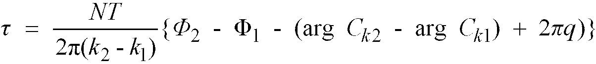
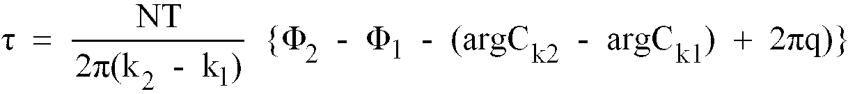
argCk1 and argCk2 represent Ck1 and Ck2 phase angles. (In this embodiment, both phase angles are 0.) τ and θ can be found from Formula 9a and Formula 9b as shown below.
[0080] In Formula 11, q is an integer indicating a given uncertainty value according to the integer multiple of 2π existing in both φ1 and φ2. If the range of the τ existence is limited, however, this q can be decided uniquely.
[0081] For example, since N=32 and k2 - k1 = 10 are satisfied in this embodiment, τ0+ 3.2qT can also be judged correct for an arbitrary integer q if τ = τ0 is a correct answer of Formula 10. If τ is assumed to exist in -1.6T < τ ≤ 1.6T, q that satisfies it, as well as τ, can be decided uniquely. And, as shown clearly in Formula 10, the range that can decide this τ uniquely is in inverse proportion to |k2 - k1|, so |k2 - k1| is selected corresponding to the timing uncertainty to be expected in the object system. In general, the range that can catch the initial timing is NT/|k2 - k1|. Thus, if the maximum value of the uncertainty to catch the timing at t=0 to be expected is τ',
it is only needed to decide k2 and k1 so that the above condition Formula 12a may be satisfied. The Formula 12a is also equivalent to the formula shown below.
[0082] To find frequencies k1' and k2', as well as phase angles φ1 and φ2 precisely in the said receiving system, signals to be Fourier-transformed can be multiplied by a window function such as the Hanning function except for rectangle ones. This operation is done in the window function generator 216 and the window function multiplier 215. The switches 214a and 214b controlled by the pilot symbol detector 227 are used to decide whether to multiply the object signal by a window function.
[0083] The method to decide frequencies, etc. when a window function is multiplied is described, for example, in the Institute of Electronics, Information and Communication Engineer Transactions; Vol. J70-A, No.5 (May, 1987), pages 503 to 798. According to this method, it is no need to carry out a Fourier transformation for every frequency to decide a frequency.
[0084] For example, if the maximum value ΔFm of the frequency shift ΔF including the uncertainty of the Doppler shift and the local oscillator is -1/(2NT) < ΔFm ≤ 1/(2NT), the Fourier transformation result is needed only for the transmission frequency fk and one more frequency above/under the fk. In general, if the maximum value ΔFm is -1/(2NT) - h/(NT) < ΔFm ≤ 1/(2NT) + h/(NT), the Fourier transformation result is needed only for the transmission frequency fk and 2(h + 1) frequencies above/under the fk. In this embodiment, the FFT 218 outputs the Fourier transformation result used toacquire timing and frequency synchronizations only to the frequency indexes k1 and k2, and 2(h + 1) frequencies above/under each of k1 and k2, assuming the expected maximum frequency as ±| 1/(2NT) + h/(NT)|. The object frequency can be estimated easily if it is multiplied by a window function. In this case, however, the frequency spectrum is spread widely. When receiving two or more frequencies, therefore, the frequency interval must be set so that those frequencies may not be set too closely. No problem will arise from the frequency interval if there is a frequency interval of 4 or more Fourier transformation output pitch frequencies. In the transmission system 1a of this embodiment, the interval between two frequencies k1=2 and k2=12 is set to 10 of the transmission frequency pitch which is over 4. So, if the frequency pitch of the Fourier transformation to be carried out on the receiver side is set to 10/4 of the transmission frequency pitch or less, the condition will be satisfied.
[0085] Fourier transformation is executed in the fast Fourier transformer 218. The frequencies k1' and k2', as well as the phase angles φ1 and φ2 are estimated in the frequency/phase estimator 219.
[0086] As explained above, the δ, τ and ΔF, Θ can be estimated from those values. Those shift values are estimated in the sampling timing controller 211 and the frequency/phase correction controller 213. δ, τ and ΔF, Θ can be estimated such way by transmitting the pilot signal using two or more frequencies.
[0087] Furthermore, such the estimation is also possible when three or more frequencies are used to transmit the pilot signal. In this case, plural sets of estimation can be obtained for δ, τ and ΔF, e by assuming the combination of two frequencies selected from those three frequencies or more as k1 and k2 sequentially. Then, the average value is obtained from part or whole of those sets of estimation to assume the required estimation values δ, τ and ΔF, Θ. This averaging operation is also executed in the sampling timing controller 211 and the frequency/phase correction controller 213.
[0088] When receiving data following the pilot symbol 53, the sampling timing controller 211 corrects the shift τ of the initial sampling phase to renew the sampling timing period T' to T'/(1 + δ), so that the timing synchronization can be acquired. The frequency/phase correction controller 213 can correct the frequency offset ΔF and the initial phase shift Θ, as well as it can allow the receiving system 2a to acquire the frequency synchronization with the transmission system 1a by controlling the derotator 212.
[0089] If the selector 214 is set to the window function multiplier 215 for receiving the pilot symbol 53, the selector is set to the noprocessing side for receiving data 55.
[0090] When the timing and frequency are synchronized, the Formula 3 of the received signal matches with the Formula 1 of the transmit signal. And, when this received signal is Fourier transformed, transmit data Ck can be reproduced collectively.
(Sampling of pilot symbols)
[0091] Next, the embodiment of this invention will be explained in relation to the pilot symbol sampling points.
[0092] Figure 5 (a) shows an ideal sampling time mainly for the pilot symbol 53. The time t=0 indicates the time to start the effective symbol in the pilot symbol 53.
[0093] When the timing is not synchronized in both transmission and receiving systems, the sampling interval T' in the receiving system 2a differs from T in the transmission system 1a. Furthermore, the time on which the pilot symbol detector 227 detects the pilot symbol 53 is shifted by td from the ideal time in some cases. When the difference between T' and T, as well as the shift td are small, N-number samples from n=0 to N-1 can be used as are to estimate frequencies and phases.
[0094] On the other hand, when the shift td is large or when the sampling interval T' is a little larger than T, the last sample or two or more samples at the sampling points within n=0 to N-1 come in the area of the data symbol 55, which is the next to the pilot symbol 53. This may cause errors in frequency and phase estimation.
[0095] Figure 5 (b) shows the sampling method for the pilot symbol 53 to avoid such the estimation error. In other words, sampling is not started within the effective symbol, but started at a time within the pilot symbol guard interval. In the example shown in Figure 5 (b), N-number samples within n=-3 to n=N-4 are sampled. Frequency and phase estimation can be made with no problem if the time lag at this sampling point is taken into consideration.
[0096] Figure 5 (c) shows another sampling method for the pilot symbol 53. In this case, sampling is started at a time within the effective symbol at the sampling interval T', but the number of sampling points is a little less than N. With this, sampling of the symbol next to the pilot one can be avoided. In the example shown in Figure 5 (c), N is assumed to be an even number and sampling is made at N/2 sampling points. In this case, when the N/2 samplings are ended, Fourier transformation can be made in the fast Fourier transformer 218. Thus, the timing synchronization can be acquired earlier. When signals are multiplied by a window function, the window function is selected according to the number of samples.
[0097] Furthermore, in case of the method shown in Figure 5 (c), the number of sampling points must be set enough to estimate the frequencies and phases transmitted as the pilot symbol 53. Concretely, the number of sampling points is N/2 and the sampling interval remains the same in this embodiment, so the Fourier transformation output frequency interval becomes double that assumed when the number of sampling points is N. As shown in Figure 3, however, since the pilot signal frequency interval is 10, the frequency interval after the Fourier transformation carried out when the number of sampling points is N/2 is 5, which is over the interval of 4 or over for assuring the required accurate estimation.
[0099] As shown in the first embodiment, if a null symbol 52 is transmitted before the pilot symbol 53, the signals at the guard interval of the pilot symbol 53 are not affected by the delay of the previous symbol. When the conception shown in Figure 5 (d) is extended, therefore, the synchronization of both timing and frequency can also be assumed only by sampling signals within the time around the guard interval of the pilot symbol 53. In general, the synchronization is acquired as follows.
[0100] Assume now that a pilot signal frequency is to be separated from the other one by a width of M transmission frequencies, that is, by M/NT [Hz] in the transmission system. On the other hand, assume that Fourier transformation is made for N/L samples at the same sampling time interval, that is, at the sampling time of ts/L for the synchronization in the receiving system. Then, the frequency pitch of this Fourier transformation becomes L times that of the Fourier transformation carried out according to the sampling at N points. The result of the Fourier transformation carried out according to the sampling at N/L points of the pilot signal separated initially by a width of M frequencies becomes a separation of M/L frequencies in width.
[0101] It is only needed to select the frequency interval and sampling time ts/L of the pilot signal so that the separation may become 4 or over. In other words, M/L ≥ 4 may be satisfied.
[0102] For example, to acquire the synchronization within the guard interval, which is 1/4 of one effective symbol time, the L value must be 4 or over. To realize this, the M value must be 16 or over. This value is independent of the N value.
(Second embodiment)
[0103] Next, the second embodiment of this invention will be explained. In this embodiment, the digital broadcasting transmission system that uses the OFDM method is the same as the transmission system 1a shown in Figure 1. The receiving system takes a different configuration, however. In the second embodiment for the receiving system, the synchronization is controlled more in detail while data symbols except for the frame synchronization symbol 52 and the pilot symbol 53 are received.
[0104] Figure 6 shows the block diagram of the receiving system for digital broadcasting of this invention.
[0105] This receiving system 2b differs from the receiving system 2a shown in Figure 4 in that this receiving system 2b is provided with a slicer (hard judge) 230, a phase error detector 231, a 90° phase shifter 232, low-pass filters 233a and 233b, and frequency converters 234a and 234b.
[0106] Just like in the receiving system 2a shown in Figure 4, signals transmitted from the transmission system 1a are caught by the antenna 201, then amplified in the high-frequency amplifier 202 and converted to intermediate frequency band signals in the local oscillator 204 controlled by the channel selection signal and in the frequency converter 203. The adjacent hamming waves and noise of these signals are suppressed in the band-pass filter (BPF) 205 that passes only N-number frequencies from the said transmission system 1a. These signals are then amplified in the intermediate frequency amplifier 206. The output from this intermediate frequency amplifier 206 is divided into two systems; one system comprising a frequency/phase correction controller 213'; a 90° phase shifter 232; a frequency converter 234a; and a low-pass filter (LPF) 233a, and the other system comprising a frequency/phase correction controller 213'; a frequency converter 234b; a low-pass filter 233b. Those signals are converted to the required complex number base band signals respectively there. The outputs from the low-pass filters 233a and 233b are sampled in the A/D converters 207a and 207b controlled by the sampling timing controller 211'.
[0107] The outputs from the A/D converters 207s and 207b control the AGC 210, and they are entered to the pilot symbol detector 227. If this pilot symbol detector 227 detects the start point of the pilot symbol 53 in a transmitted frame, the selectors 214a and 214b connect the output signals from the A/D converters 207a and 207b to the window function multiplier 215. As a result, the output signals from the A/D converters 207a and 207b are multiplied by the window function from the window function generator 216. After this, the selectors 214a and 214b are connected according to the signal from the pilot symbol detector 227 so that the output signals from the A/D converters 207a and 207b are connected to the next device directly without being multiplied by any window function for signals other than the pilot symbol.
[0108] The output signal from the selector 214b, just like in the receiving system 2a shown in the first embodiment, passes the S/P converter 217, then it is Fourier-transformed in the fast Fourier transformer (FFT) 218.
[0109] If the pilot symbol 53 is Fourier-transformed, the output from the fast Fourier transformer 218 is transmitted to the frequency/phase estimator 219. The frequency and phase of the pilot symbol are estimated here. The estimation result is passed to both the frequency/phase correction controller 213' and the sampling timing controller 211'. This receiving system 2b uses the estimation result to acquire the synchronization of frequency and timing for transmit signals. This operation principle is as shown in the first embodiment.
[0110] In the first embodiment, the A/D converter 207 operates with a fixed sampling frequency and receives signals in the necessary timing phase from the interpolator 209. On the other hand, the receiving system 2b in the second embodiment controls the sampling time in the A/D converters 207a and 207b directly.
[0111] In the first embodiment, frequencies and phases are corrected in the frequency/phase correction controller 213 according to the discrete time signal. On the other hand, in the second embodiment, frequencies and phases are corrected in the frequency/phase correction controller 213' before they are converted from analog signals to digital signals.
[0112] In the second embodiment, a slicer 230 and a phase error detector 231 are provided, as shown in Figure 6, to control synchronization more in detail while symbols other than the frame synchronization symbol 52 and the pilot symbol 53 are received.
[0113] The slicer 230 makes a hard-judgment for the output from the P/S converter 220 to select the most geometrical values from the complex numbers Ck that might be received. The selected complex numbers are Ck=1, -1, j, and -j in case of the transmission system shown in Figure 1.
[0114] Assume now that synchronization is almost established using the pilot symbol 53 and the Θ, ΔF, τ, and δ are very small values. At this time, the demodulation signal Ck1. to the data Ck1 whose frequency index of a symbol is k1 (that is, the output corresponding to Fourier-transformed frequency k1) is given as shown in Formula 13.
[0115] Thus, the phase difference θ1 to be applied to Ck1. becomes as shown below when Ck1 is assumed as the reference.
In the same way, the phase difference θ2 to be applied to k2 becomes as shown below.
[0117] As shown in Formula 15 clearly, the difference of the phase errors between the received demodulated signal and the hard-judged signal Δθ = θ2 - θ1 includes only the sample timing errors and τ. If the sampling timing is controlled so that this Δθ may become 0 using PLL, etc., then the timing can be controlled precisely.
[0118] In the receiving system 2b shown in Figure 6, the slicer 230 judges Ck when receiving symbols other than the frame synchronization symbol and the pilot symbol, and the phase error detector 231 finds the said θ1, θ2 for proper k1 and k2. Furthermore, the sampling timing controller 211' uses these θ1, θ2 to find the Δθ to control the timing.
[0119] In general, the number of transmission frequencies N is a few tens or more. The said Δθ can also be found for many kinds of k1 and k2 combinations. In this case, the average value is found from part or all the Δθ values to assume it as the required Δθ.
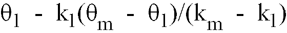
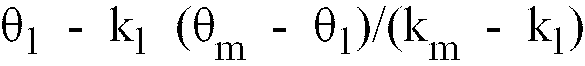
[0120] On the other hand, from Formula 14a and Formula 15, the following can be obtained approximately.
As shown in Formula 16 clearly, θ1 - k1Δθ/(k2 - k1) includes only frequency/phase correction control parameters Θ and ΔF. Thus, the control can be made precisely by controlling the frequency/phase correction so that this θ1 - k1Δθ/(k2 - k1) may become 0.
[0121] In the receiving system 2b of this invention shown in Figure 6, just like the timing control, θ1 - k1Δθ/(k2 - k1) is calculated in the frequency/phase correction controller 213' from the found θ1, θ2 for carrier recovery.
[0122] The demodulated symbols of data 55 output from the P/S converter 220 are entered to the communication channel decoder 224, then restored to original image information, audio information, or data in the demultiplexer 225 and the information decoder 226. This completes the explanation for the configuration and operation of the receiving system of this invention.
1. A digital broadcasting system comprising a transmission system (Fig. 1) and a receiving
system (Fig. 4, Fig. 6), said transmission system using the OFDM transmission method
in which signals are transmitted using plural frequencies mutually orthogonal and
with frequency intervals of 1/(NT), the duration of transmitting one transmission
symbol comprising one guard interval followed by one effective symbol interval, and
in which also, at fixed intervals, a pilot signal (53) is transmitted using two or
more frequencies (k1, k2, ...) among said plural frequencies, said receiving system receiving the signals
transmitted by said transmission system and comprising means (219) for estimating
the timing period offset (δ), the timing phase offset (τ), the frequency offset (ΔF),
or the phase offset (Θ)or a combination of some of these or estimating all of these,
characterized in that
said estimating means use the Fourier transformation output of the signal received during a time interval with a duration of less than or equal to one transmission symbol interval and corresponding to the transmission symbol including said pilot signal;
and a sampling timing control means (211) for carrying out, using said estimated values, acquisition of the timing synchronization, or a frequence/phase compensation control means (213) for carrying out, using said estimated values, acquisition of the frequency synchronization for frequency conversion, or both of these control means for acquiring the synchronization of both these parameters.
2. The digital broadcasting system according to claim 1, in which the receiving system
estimates, among said offset values, the timing period offset δ, using the equation
δ = (k2' - k1') / (k2 - k1) - 1 and estimates the frequency offset ΔF for frequency conversion, using the equation
ΔF = (k2k1' - k1k2') / [NT (k2' - k1')], where k1 and k2 are the transmission frequencies of said pilot signal, and k1' and k2' are the estimated frequencies of said pilot signal in said receiving system.
3. The digital broadcasting system according to claim 1, in which the receiving system
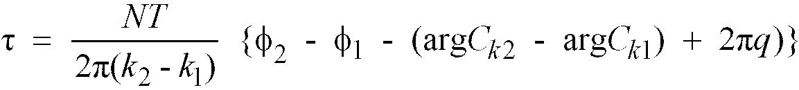
estimates, among said offset values, the timing phase offset τ, using the equation:
and estimates the phase offset Θ with

where k1 and k2 are the transmission frequencies of said pilot signal, and argCk1, argCk2 are the phase angles of the pilot signal transmission symbols Ck1 and Ck2, k1' and k2' are the estimated frequencies of said pilot signal in said receiving system, and Φ1 and Φ2 are the estimated phase angles and q is an integer.
and estimates the phase offset Θ with
where k1 and k2 are the transmission frequencies of said pilot signal, and argCk1, argCk2 are the phase angles of the pilot signal transmission symbols Ck1 and Ck2, k1' and k2' are the estimated frequencies of said pilot signal in said receiving system, and Φ1 and Φ2 are the estimated phase angles and q is an integer.
4. The digital broadcasting system according to claim 2 or 3, wherein, if the pilot signal
comprises three or more frequencies, different values are obtained for at least one
of the offset values δ, ΔF, τ and Θ by combining in possible pairs of the frequencies
of the pilot signal and wherein, for at least one of the offset values, an average
is deducted from some or all of the different so-obtained values in order to obtain
the final timing period offset ferent so-obtained values in order to obtain the final
timing period offset (δ), the final frequency offset (ΔF), the final timing phase
offset (τ) or the final phase offset (Θ), or a combination of some of these or all
of these final offsets, or a combination of some of these or all of these final offsets.
5. A digital broadcasting system according to claim 1, in which, at the time of transmitting
said pilot signal, the transmitting system uses from among the plural frequencies
for transmission, at least two or more frequencies including two or more frequencies
for said pilot signal, so that the signal among these frequencies including said pilot
signal that is closest to each pilot frequency signal is such that there is a frequency
interval of M times or more (M ≥ 1) of the transmission frequency interval 1 / (NT)
between that signal and the corresponding pilot signal; and also,
in the receiving system, the reception period of the received signal including said pilot signal for carrying out Fourier transformation in order to carry out acquisition of the timing synchronization, or acquisition of the frequency synchronization, or for acquiring the synchronization of both of these parameters, is almost 1/L times one valid symbol interval, and both L and M satisfy the condition M/L ≥4.
in the receiving system, the reception period of the received signal including said pilot signal for carrying out Fourier transformation in order to carry out acquisition of the timing synchronization, or acquisition of the frequency synchronization, or for acquiring the synchronization of both of these parameters, is almost 1/L times one valid symbol interval, and both L and M satisfy the condition M/L ≥4.
6. The digital broadcasting system according to claims 1 to 5, wherein, in order to estimate
the timing period offset (δ), timing phase offset (τ), frequency offset (ΔF), phase
offset (Θ) or to estimate a combination of some of these or to estimate all of these,
the receiving system comprises at least means for carrying out a Fourier transformation
by multiplying the received signals by a window function other than a rectangular
window function, such as a Hanning window function.
7. A digital broadcasting system in which transmission is done using the OFDM transmission
method in which signals are transmitted using plural frequencies mutually orthogonal
and with frequency intervals of 1/NT, the duration of transmitting one transmission
symbol comprising one guard interval followed by one effective symbol interval, and
in which also, at fixed intervals, a pilot signal (53) is transmitted, using two or
more frequencies among said plural frequencies,
said digital broadcasting comprising a receiving system (Fig. 4), which further comprises means (219) for estimating the timing period offset (δ), the timing phase offset (τ), the frequency offset (ΔF) or the phase offset (Θ), or a combination of some of these, or estimating all of these,
characterized in that
said estimating means uses the Fourier transformation output of the signal received during an interval with a duration of less than or equal to one transmission symbol interval and corresponding to one transmission symbol including said pilot signal;
and a sampling timing control means (211) for carrying out, using said estimated values, acquisition of the timing synchronization, or a frequence/phase compensation control means (213) for carrying out, using said estimated values, acquisition of the frequency synchronization for frequency conversion, or both of these control means for acquiring the synchronization of both these parameters.
8. A digital broadcasting system according to claim 7, wherein, in order to estimate
the timing period offset (δ), the timing phase offset (τ), the frequency offset (ΔF)
or the phase offset (Θ), or to estimate a combination of some of these, or to estimate
all of these, the receiving system comprises at least means for carrying out Fourier
transformation by multiplying said received signal by a window function other than
a rectangular window function, such as a Harining window function.
9. A digital broadcasting system according to claim 1, wherein the receiving system comprises
a means in which the Fourier transformation output of received signal is subjected
to hard judgment (230), and the phase difference between the result of judgment and
said received signal is used to carry out timing synchronization control or frequency
synchronization control, or both types of synchronization controls.
10. A digital broadcasting system according to claim 7, comprising a sampling timing control
means so that, at least for two or more frequency signals, the Fourier transformation
output of the received signals are subjected to hard judgment, and the phase differences
θ1, θ2, ... between the results of judgment and said received signals before the hard judgment
are obtained, and among these plural phase differences, either the difference between
two appropriate phase differences (for example, Δθ = θ1 - θ2) becomes 0, or the average of some or all of the differences between the phase differences
that can be obtained becomes 0.
11. A digital broadcasting system according to claim 7 above, and characterized by the fact that it comprises a means for carrying out frequency/phase compensation
control of a signal having at least two or more frequencies of k=k1, k2, ..., by subjecting the Fourier transformation output of the received signals to
hard judgment, and obtaining the phase differences θ1, θ2, ... between the results of judgment and said received signals before the hard judgment,
and carrying out the control so that, for some suitable values of 1 and m, the value
of
becomes 0, or the average of some or all of the values that can be obtained by
becomes 0.
becomes 0, or the average of some or all of the values that can be obtained by
becomes 0.
12. A digital broadcasting system according to claim 1, wherein, when Fourier transformation
of the received signal is carried out for timing synchronization acquisition, or frequency
synchronization acquisition, or for acquisition of both these types of synchronization,
the frequency interval of the output result of such Fourier transformation is 1/4th or less of the frequency interval transmitted by the transmitting system at the time
of transmitting the signal.
13. A digital broadcasting system according to claim 1, wherein, when Fourier transformation
of the received signal is carried out for timing synchronization acquisition, or frequency
synchronization acquisition, or for acquisition of both these types of synchronization,
the sampling of the received signal is started at an instant of time within the guard
interval of the received transmission symbol.
14. A digital broadcasting system according to claims 7, 8, 10 and 11, in which, at the
time of transmitting said pilot signal, the transmitting system uses, from among the
plural frequencies for transmission, at least two or more frequencies including two
or more frequencies for said pilot signal, so that the signal among these frequencies
including said pilot signal that is closest to each pilot frequency signal is such
that there is a frequency interval of M times or more (M ≥ 1) of the transmission
frequency interval 1 / (NT) between that signal and the corresponding pilot signal;
and also,
in the receiving system, the reception period of the received signal including said pilot signal for carrying out Fourier transformation in order to carry out acquisition of the frequency synchronization of both of these parameters, is almost 1/L times one valid symbol interval, and both L and M satisfy the condition M/L ≥4.
in the receiving system, the reception period of the received signal including said pilot signal for carrying out Fourier transformation in order to carry out acquisition of the frequency synchronization of both of these parameters, is almost 1/L times one valid symbol interval, and both L and M satisfy the condition M/L ≥4.
1. Digitales Rundfunksystem, welches ein Übertragungssystem (Fig. 1) und ein empfangendes
System (Fig. 4, Fig. 6) aufweist, wobei das Übertragungssystem das OFDM-Übertragungsverfahren
verwendet, in welchem Signale übertragen werden unter Verwendung mehrfacher wechselseitig
orthogonaler Frequenzen und mit Frequenzintervallen von 1/(NT), wobei die Dauer der
Übertragung eines Übertragungszeichens ein Schutzintervall, gefolgt durch ein wirksames
Zeichenintervall, aufweist, und in welchem auch, zu festgelegten Intervallen, ein
Pilotsignal (53) übertragen wird unter Verwendung zweier oder mehrerer Frequenzen
(k1, k2, ...) zwischen den mehrfachen Frequenzen, wobei das Empfangssystem die Signale, welche
übertragen werden durch das Übertragungssystem, empfängt und Mittel (219) aufweist
für die Schätzung des Zeitperioden-Offsets (δ), des Zeitphasen-Offsets (τ), des Frequenz-Offsets
(ΔF) oder des Phasen-Offsets (Θ) oder einer Kombination einiger dieser oder die Schätzung
aller dieser,
dadurch gekennzeichnet, dass
das Schätzmittel die Fourier-transfomierte Ausgabe des Signals verwendet, welches während eines Zeitintervalls mit einer Dauer von weniger als ein oder gleich zu einem Übertragungszeichenintervall empfangen wurde und dem Übertragungszeichen einschließlich des Pilotsignals entspricht; und ein Abtast-Zeitsteuermittel (211) für die Ausführung, unter Verwendung der geschätzten Werte, der Erlangung der Zeitsynchronisation oder ein Frequenz-/Phasen-Kompensationssteuermittel (213) für die Ausführung, unter Verwendung der geschätzten Werte, der Erlangung der Frequenzsynchronisation für die Frequenzwandlung, oder beide dieser Steuermittel für die Erlangung der Synchronisation beider dieser Parameter.
2. Digitales Rundfunksystem gemäß Anspruch 1, in welchem das empfangende System, zwischen
den Offset-Werten, den Zeitperioden-Offset δ schätzt, unter Verwendung der Gleichung
δ = (k2' - k1') / (k2 - k1) - 1 und den Frequenz-Offset ΔF für die Frequenzwandlung schätzt, unter Verwendung
der Gleichung ΔF = (k2k1' - k1k2') / [NT (k2' - k1')], wobei k1 und k2 die Übertragungsfrequenzen des Pilotsignals sind, und k1' und k2' die geschätzten Frequenzen des Pilotsignals in dem empfangenden System sind.
3. Digitales Rundfunksystem gemäß Anspruch 1, in welchem das empfangende System, zwischen
den Offset-Werten, den Zeitphasen-Offset τ schätzt unter Verwendung der Gleichung:
und den Phasen-Offset θ schätzt mit

wobei k1 und k2 die Übertragungsfrequenzen des Pilotsignals sind, und argCk1, argCk2 die Phasenwinkel der Übertragungszeichen Ck1 und Ck2 des Pilotsignals sind, k1' und k2' die geschätzten Frequenzen des Pilotsignals in dem empfangenden System sind, und Φ1 und Φ2 die geschätzten Phasenwinkel sind und q eine ganze Zahl ist.
und den Phasen-Offset θ schätzt mit
wobei k1 und k2 die Übertragungsfrequenzen des Pilotsignals sind, und argCk1, argCk2 die Phasenwinkel der Übertragungszeichen Ck1 und Ck2 des Pilotsignals sind, k1' und k2' die geschätzten Frequenzen des Pilotsignals in dem empfangenden System sind, und Φ1 und Φ2 die geschätzten Phasenwinkel sind und q eine ganze Zahl ist.
4. Digitales Rundfunksystem gemäß Anspruch 2 oder 3, wobei, falls das Pilotsignal drei
oder mehr Frequenzen aufweist, verschiedene Werte erhalten werden für mindestens einen
der Offset-Werte δ, ΔF, τ und Θ durch Kombination in mögliche Paare der Frequenzen
des Pilotsignals, und wobei, für mindestens einen der Offset-Werte, ein Mittelwert
gefolgert ist aus einigen oder allen der verschiedenen solchermaßen erlangten Werte,
um den letzten Zeitperioden-Offset (δ), den letzten Frequenz-Offset (ΔF), den letzten
Zeitphasen-Offset (τ) oder den letzten Phasen-Offset (θ) oder eine Kombination einiger
dieser oder aller dieser letzten Offsets oder eine Kombination einiger dieser oder
aller dieser letzten Offsets zu erhalten.
5. Digitales Rundfunksystem gemäß Anspruch 1, in welchem, zur der Zeit der Übertragung
des Pilotsignals, das übertragende System von zwischen den mehrfachen Frequenzen für
die Übertragung mindestens zwei oder mehr Frequenzen einschließlich zwei oder mehr
Frequenzen für das Pilotsignal verwendet, so dass das Signal zwischen diesen Frequenzen
einschließlich des Pilotsignals, welches am nächsten zu jeder Frequenz eines Pilotsignals
ist, solchermaßen ist, dass dort ein Frequenzintervall von M-mal oder mehr (M ≥ 1)
des Übertragungsfrequenzintervalls 1/(NT) zwischen diesem Signal und dem entsprechenden
Pilotsignal ist; und ebenso, ist in dem empfangenden System die Empfangsperiode des
empfangenen Signals, einschließlich des Pilotsignals, für die Ausführung einer Fourier-Transformation,
um die Erlangung der Zeitsynchronisation oder die Erlangung der Frequenzsynchronisation
auszuführen, oder um die Synchronisation von diesen beiden Parametern zu erlangen,
beinahe 1/L-mal ein gültiges Zeichenintervall, und sowohl L als auch M erfüllen die
Bedingung M/L ≥4.
6. Digitales Rundfunksystem gemäß Ansprüchen 1 bis 5, wobei, um den Zeitperioden-Offset
(δ), den Zeitphasen-Offset (τ), den Frequenz-Offset (ΔF), den Phasen-Offset (Θ) zu
schätzen oder eine Kombination einiger dieser zu schätzen oder alle diese zu schätzen,
das empfangende System mindestens ein Mittel aufweist für die Ausführung einer Fourier-Transformation
durch Multiplizieren der empfangenen Signale mit einer Fensterfunktion, welche eine
andere ist als eine rechtwinklige Fensterfunktion, wie eine Hanning-Fensterfunktion.
7. Digitales Rundfunksystem, in welchem die Übertragung durchgeführt wird unter Verwendung
des OFDM-Übertragungsverfahrens, in welchem Signale übertragen werden unter Verwendung
mehrfacher wechselseitig orthogonaler Frequenzen und mit Frequenzintervallen von 1/NT,
wobei die Dauer der Übertragung eines Übertragungszeichens ein Schutzintervall, gefolgt
durch ein wirksames Zeichenintervall, aufweist, und in welchem auch, zu festgelegten
Intervallen, ein Pilotsignal (53) übertragen wird unter Verwendung zweier oder mehrerer
Frequenzen zwischen den mehrfachen Frequenzen,
wobei der digitale Rundfunk ein empfangendes System (Fig. 4) aufweist, welches weiter Mittel (219) aufweist für die Schätzung des Zeitperioden-Offsets (δ), des Zeitphasen-Offsets (τ), des Frequenz-Offsets (ΔF) oder des Phasen-Offsets (θ), oder eine Kombination einiger dieser, oder die Schätzung aller dieser,
dadurch gekennzeichnet, dass
das Schätzmittel die Fourier-transformierte Ausgabe des Signals verwendet, welches während eines Intervalls mit einer Dauer von weniger als ein oder gleich zu einem Übertragungszeichenintervall empfangen wurde und einem Übertragungszeichen einschließlich des Pilotsignals entspricht;
und ein Abtast-Zeitsteuermittel (211) für die Ausführung, unter Verwendung der geschätzten Werte, der Erlangung der Zeitsynchronisation oder ein Frequenz-/Phasen-Kompensationssteuermittel (213) für die Ausführung, unter Verwendung der geschätzten Werte, der Erlangung der Frequenzsynchronisation für die Frequenzwandlung, oder beide dieser Steuermittel für die Erlangung der Synchronisation beider dieser Parameter.
8. Digitales Rundfunksystem gemäß Anspruch 7, wobei, um den Zeitperioden-Offset (δ),
den Zeitphasen-Offset (τ), den Frequenz-Offset (ΔF) oder den Phasen-Offset (θ) zu
schätzen, oder eine Kombination einiger dieser zu schätzen, oder alle diese zu schätzen,
das empfangende System mindestens ein Mittel aufweist für die Ausführung einer Fourier-Transformation
durch Multiplizieren des empfangenen Signals mit einer Fensterfunktion, welche eine
andere ist als eine rechtwinklige Fensterfunktion, wie eine Hanning-Fensterfunktion.
9. Digitales Rundfunksystem gemäß Anspruch 1, wobei das empfangende System ein Mittel
aufweist, in welchem die Fourier-transformierte Ausgabe eines empfangenen Signals
einer harten Beurteilung (230) unterzogen ist, und die Phasendifferenz zwischen dem
Ergebnis der Beurteilung und dem empfangenen Signal Verwendung findet, um eine Zeitsynchronisationssteuerung
oder eine Frequenzsynchronisationssteuerung auszuführen, oder beide Typen von Synchronisationssteuerungen.
10. Digitales Rundfunksystem gemäß Anspruch 7, ein Abtast-Zeitsteuermittel aufweisend,
so dass, mindestens für zwei oder mehr Frequenzsignale, die Fourier-transformierten
Ausgabe der empfangenen Signale einer harten Beurteilung unterzogen ist, und die Phasendifferenzen
θ1, θ2,... zwischen den Ergebnissen der Beurteilung und den empfangenen Signalen vor der
harten Beurteilung erhalten werden, und zwischen diesen mehrfachen Phasendifferenzen
entweder die Differenz zwischen zwei passenden Phasendifferenzen (z.B. Δθ = θ1 - θ2) 0 wird, oder der Mittelwert einiger oder aller der Differenzen zwischen den Phasendifferenzen,
welche erhalten werden können, 0 wird.
11. Digitales Rundfunksystem gemäß obigem Anspruch 7, und gekennzeichnet durch die Tatsache, dass es ein Mittel aufweist für die Ausführung einer Frequenz-/Phasenkompensationssteuerung
eines Signals, welches mindestens zwei oder mehr Frequenzen mit k=k1, k2, ...besitzt, durch Unterziehttng der Fourier-transformierten Ausgabe der empfangenen Signale einer harten
Beurteilung, und Erlangung der Phasendifferenzen θ1, θ2, ... zwischen den Ergebnissen der Beurteilung und den empfangenen Signalen vor der
harten Beurteilung, und die Steuerung solchermaßen ausführend, dass für einige passende
Werte von 1 und m der Wert von

0 wird, oder der Mittelwert einiger oder aller der Werte, welche durch

erlangt werden können, 0 wird.
0 wird, oder der Mittelwert einiger oder aller der Werte, welche durch
erlangt werden können, 0 wird.
12. Digitales Rundfunksystem gemäß Anspruch 1, wobei, falls eine Fourier-Transformation
des empfangenen Signals ausgeführt wird für die Erlangung einer Zeitsynchronisation
oder die Erlangung einer Frequenzsynchronisation oder die Erlangung beider dieser
Typen der Synchronisation, das Frequenzintervall des Ausgaberesultats einer solchen
Fourier-Transformation 1/4 oder weniger des Frequenzintervalls ist, welches durch
das übertragende System zu dem Zeitpunkt der Übertragung des Signals übertragen wird.
13. Digitales Rundfunksystem gemäß Anspruch 1, wobei, falls eine Fourier-Transformation
des empfangenen Signals ausgeführt wird für die Erlangung einer Zeitsynchronisation
oder die Erlangung einer Frequenzsynchronisation oder die Erlangung beider dieser
Typen der Synchronisation, das Abtasten des empfangenen Signals zu einen Zeitpunkt
der Zeit innerhalb des Schutzintervalls des empfangenen Übertragungszeichens gestartet
wird.
14. Digitales Rundfunksystem gemäß den Ansprüchen 7, 8, 10 und 11, in welchem, zu der
Zeit der Übertragung des Pilotsignals das übertragende System, von zwischen den mehrfachen
Frequenzen für die Übertragung, mindestens zwei oder mehr Frequenzen einschließlich
zwei oder mehr Frequenzen für das Pilotsignal verwendet, so dass das Signal zwischen
diesen Frequenzen einschließlich des Pilotsignals, welches am nächsten zu jeder Frequenz
eines Pilotsignals solchermaßen ist, dass dort ein Frequenzintervall von M-mal oder
mehr (M ≥ 1) des Übertragungsfrequenzintervalls 1/(NT) zwischen diesem Signal und
dem entsprechenden Pilotsignal ist; und ebenso,
ist in dem empfangenden System die Empfangsperiode des empfangenen Signals einschließlich des Pilotsignals für die Ausführung einer Fourier-Transformation, um die Erlangung der Frequenzsynchronisation beider dieser Parameter auszuführen, beinahe 1/L-mal ein gültiges Zeichenintervall, und sowohl L als auch M erfüllen die Bedingung M/L ≥ 4.
ist in dem empfangenden System die Empfangsperiode des empfangenen Signals einschließlich des Pilotsignals für die Ausführung einer Fourier-Transformation, um die Erlangung der Frequenzsynchronisation beider dieser Parameter auszuführen, beinahe 1/L-mal ein gültiges Zeichenintervall, und sowohl L als auch M erfüllen die Bedingung M/L ≥ 4.
1. Système de diffusion numérique comprenant un système d'émission (figure 1) et un système
de réception (figure 4, figure 6), ledit système d'émission utilisant le procédé d'émission
OFDM dans lequel les signaux sont émis en utilisant plusieurs fréquences mutuellement
orthogonales et avec des intervalles de fréquence de 1 / (NT), la durée d'émission
d'un symbole d'émission comprenant un intervalle de veille suivi d'un intervalle de
symbole effectif, et aussi dans lequel, à des intervalles fixes, un signal pilote
(53) est émis en utilisant deux fréquences ou plus (k1, k2, ...) parmi lesdites plusieurs fréquences, ledit système de réception recevant les
signaux émis par ledit système d'émission et comprenant un moyen (219) d'évaluation
du décalage de période de cadencement (δ), du décalage de phase de cadencement (τ),
du décalage de fréquence (ΔF) ou du décalage de phase (Θ) ou une combinaison de tout
ou partie de ces décalages,
caractérisé en ce que
ledit moyen d'évaluation utilise la transformée de Fourier du signal reçu durant un intervalle de temps d'une durée inférieure ou égale à un intervalle de symbole d'émission et correspondant au symbole d'émission incluant ledit signal pilote ;
et un moyen de commande de cadencement d'échantillonnage (211) pour exécuter, en utilisant lesdites valeurs évaluées, l'acquisition de la synchronisation de cadencement, ou bien un moyen de commande de compensation de fréquence / phase (213) pour exécuter, en utilisant lesdites valeurs évaluées, l'acquisition de la synchronisation de fréquence pour un changement de fréquence, ou les deux moyens de commande à la fois pour l'acquisition de la synchronisation de ces deux paramètres.
2. Système de diffusion numérique selon la revendication 1, dans lequel le système de
réception évalue, entre lesdites valeurs de décalage, le décalage de période de cadencement
δ, en utilisant l'équation δ = (k2' - k1') / (k2- k1) - 1 et évalue le décalage de fréquence ΔF pour un changement de fréquence, en utilisant
l'équation ΔF = (k2k1' - k1k2') / [NT (k2' - k1')], où k1 et k2 sont les fréquences d'émission dudit signal pilote, et k1' et k2' sont les fréquences évaluées dudit signal pilote dans ledit système de réception.
3. Système de diffusion numérique selon la revendication 1, dans lequel le système de
réception évalue, entre lesdites valeurs de décalage, le décalage de phase de cadencement
τ, en utilisant l'équation :
et évalue le décalage de phase Θ avec

où k1 et k2 sont les fréquences d'émission dudit signal pilote , et argCk1, argCk2 sont les angles de phase des symboles d'émission du signal pilote Ck1 et Ck2, k1' et k2' sont les fréquences évaluées dudit signal pilote dans ledit système de réception, et Φ1 et Φ2 sont les angles de phase évalués et q est un entier.
et évalue le décalage de phase Θ avec
où k1 et k2 sont les fréquences d'émission dudit signal pilote , et argCk1, argCk2 sont les angles de phase des symboles d'émission du signal pilote Ck1 et Ck2, k1' et k2' sont les fréquences évaluées dudit signal pilote dans ledit système de réception, et Φ1 et Φ2 sont les angles de phase évalués et q est un entier.
4. Système de diffusion numérique selon les revendications 2 ou 3, dans lequel, si le
signal pilote comprend trois fréquences ou plus, on obtient des valeurs différentes
pour au moins l'une des valeurs de décalage δ, ΔF, τ et Θ en combinant en couples
possibles les fréquences du signal pilote et dans lequel, pour au moins une de ces
valeurs de décalage, une moyenne est déduite de certaines ou de toutes les valeurs
différentes ainsi obtenues dans le but d'obtenir le décalage final de période de cadencement
(δ), le décalage final de fréquence (ΔF), le décalage final de phase de cadencement
(τ), ou le décalage final de phase (Θ), ou une combinaison de tout ou partie de ces
décalages finals.
5. Système de diffusion numérique selon la revendication 1, dans lequel, au moment d'émettre
ledit signal pilote, le système d'émission utilise, parmi l'ensemble des fréquences
d'émission, au moins deux fréquences ou plus incluant deux fréquences ou plus pour
ledit signal pilote, de sorte que le signal parmi ces fréquences incluant ledit signal
pilote qui est le plus proche de chaque signal de fréquence pilote est tel qu'il y
a un intervalle de fréquence de M fois ou plus (M ≥ 1) l'intervalle de fréquence d'émission
1 / (NT) entre le signal et le signal pilote correspondant ; et aussi
dans le système de réception, la période de réception du signal reçu incluant ledit signal pilote pour exécuter la transformation de Fourier dans le but de réaliser l'acquisition de la synchronisation de cadencement, ou bien l'acquisition de la synchronisation de fréquence, ou encore l'acquisition de la synchronisation de ces deux paramètres, est presque 1 / L fois un intervalle de symbole de validation, et L et M satisfont tous deux à la condition M / L ≥ 4.
dans le système de réception, la période de réception du signal reçu incluant ledit signal pilote pour exécuter la transformation de Fourier dans le but de réaliser l'acquisition de la synchronisation de cadencement, ou bien l'acquisition de la synchronisation de fréquence, ou encore l'acquisition de la synchronisation de ces deux paramètres, est presque 1 / L fois un intervalle de symbole de validation, et L et M satisfont tous deux à la condition M / L ≥ 4.
6. Système de diffusion numérique selon les revendications 1 à 5, dans lequel, afin d'évaluer
le décalage de période de cadencement (δ), le décalage de phase de chronométrage (τ),
le décalage de fréquence (ΔF), le décalage de phase (Θ) ou bien d'évaluer une combinaison
de tout ou partie de ces décalages, le système de réception comprend au moins un moyen
pour exécuter une transformation de Fourier en multipliant les signaux reçus par une
fonction à fenêtre autre qu'une fonction à fenêtre rectangulaire, telle qu'une fonction
à fenêtre de Hanning.
7. Système de diffusion numérique dans lequel une émission est faite en utilisant le
procédé d'émission OFDM dans lequel les signaux sont émis en utilisant plusieurs fréquences
mutuellement orthogonales et avec des intervalles de fréquence de 1 / NT, la durée
d'émission d'un symbole d'émission comprenant un intervalle de veille suivi d'un intervalle
de symbole effectif, et aussi dans lequel, à des intervalles fixes, un signal pilote
(53) est émis en utilisant deux fréquences ou plus parmi lesdites plusieurs fréquences,
ledit système de diffusion numérique comprenant un système de réception (figure 4), qui en plus comporte un moyen (219) pour évaluer le décalage de période de cadencement (δ), le décalage de phase de cadencement (τ), le décalage de fréquence (ΔF) ou le décalage de phase (Θ), ou une combinaison de tout ou partie de ces décalages,
caractérisé en ce que
ledit moyen d'évaluation utilise la transformée de Fourier du signal reçu durant un intervalle d'une durée inférieure ou égale à un intervalle de symbole d'émission et correspondant à un symbole d'émission incluant ledit signal pilote ;
et un moyen de commande de cadencement d'échantillonnage (211) pour exécuter, en utilisant lesdites valeurs évaluées, l'acquisition de la synchronisation de cadencement, ou un moyen de commande de compensation de fréquence / phase (213) pour exécuter, en utilisant lesdites valeurs évaluées, l'acquisition de la synchronisation de fréquence pour un changement de fréquence, ou les deux moyens de commande à la fois pour l'acquisition de la synchronisation de ces deux paramètres.
8. Système de diffusion numérique selon la revendication 7, dans lequel, dans le but
d'évaluer le décalage de période de cadencement (δ), le décalage de phase de cadencement
(τ), le décalage de fréquence (ΔF) ou le décalage de phase (Θ), ou pour évaluer une
combinaison de tout ou partie de ces décalages, le système de réception comprend au
moins un moyen pour exécuter une transformation de Fourier en multipliant ledit signal
reçu par une fonction à fenêtre autre qu'une fonction à fenêtre rectangulaire, telle
qu'une fonction à fenêtre de Hanning.
9. Système de diffusion numérique selon la revendication 1, dans lequel le système de
réception comprend un moyen dans lequel la transformée de Fourier du signal reçu est
soumise à une détermination sévère (230), et la différence de phase entre le résultat
de détermination et ledit signal reçu est utilisée pour exécuter la commande de synchronisation
de cadencement, ou la commande de synchronisation de fréquence, ou pour les deux types
de commandes de synchronisation.
10. Système de diffusion numérique selon la revendication 7, comprenant un moyen de commande
de cadencement d'échantillonnage de sorte que, au moins pour deux signaux de fréquence
ou plus, la transformée de Fourier des signaux reçus est soumise à une détermination
sévère, et les différences de phase θ1, θ2, ... entre les résultats de détermination et lesdits signaux reçus avant la détermination
sévère sont obtenues, et parmi ces plusieurs différences de phase, soit la différence
entre deux différences de phase appropriées (par exemple Δθ = θ1 - θ2) devient nulle, soit la moyenne de certaines ou toutes ces différences entre les
différences de phase qui peuvent être obtenues devient nulle.
11. Système de diffusion numérique selon la revendication 7 ci-dessus, et caractérisée par le fait qu'il comprend un moyen pour exécuter une commande de compensation de fréquence / phase
d'un signal ayant au moins deux fréquences ou plus de k = k1, k2, ..., en soumettant la transformée de Fourier des signaux reçus à une détermination
sévère, et en obtenant les différences de phase θ1, θ2, ... entre les résultats de détermination et lesdits signaux reçus avant la détermination
sévère, et pour exécuter la commande de sorte que, pour certaines valeurs appropriées
de 1 et m, la valeur de

devient nulle, ou la moyenne de tout ou partie de ces valeurs qui peut être obtenue par

devient nulle.
devient nulle, ou la moyenne de tout ou partie de ces valeurs qui peut être obtenue par
devient nulle.
12. Système de diffusion numérique selon la revendication 1, dans lequel, quand la transformation
de Fourier du signal reçu est exécutée pour l'acquisition de synchronisation de cadencement,
ou pour l'acquisition de la synchronisation de fréquence, ou pour l'acquisition de
ces deux types de synchronisation, l'intervalle de fréquence d'une transformée de
Fourier de ce type est 1/4 ou moins de l'intervalle de fréquence émis par le système
d'émission au moment de l'émission du signal.
13. Système de diffusion numérique selon la revendication 1, dans lequel, quand la transformation
de Fourier du signal reçu est exécutée pour l'acquisition de la synchronisation de
cadencement, ou l'acquisition de la synchronisation de fréquence, ou pour l'acquisition
de ces deux types de synchronisation, l'échantillonnage du signal reçu démarre à un
instant dans le temps compris dans l'intervalle de veille du symbole d'émission reçu.
14. Système de diffusion numérique selon les revendications 7, 8, 10 et 11, dans lequel,
au moment de l'émission dudit signal pilote, le système d'émission utilise, parmi
les plusieurs fréquences d'émission , au moins deux fréquences ou plus incluant deux
fréquences ou plus pour ledit signal pilote, de sorte que le signal parmi ces fréquences
incluant ledit signal pilote qui est le plus proche de chaque signal de fréquence
est tel qu'il y a un intervalle de fréquence de M fois ou plus (M ≥ 1) l'intervalle
de fréquence d'émission 1 / (NT) entre ce signal et le signal pilote correspondant
; et aussi,
dans le système de réception, la période de réception du signal reçu incluant ledit signal pilote pour exécuter une transformation de Fourier dans le but de réaliser l'acquisition de la synchronisation de fréquence de ces deux paramètres, est presque 1 / L fois un intervalle de symbole de validation, et L et M satisfont tous deux à la condition M / L ≥ 4.
dans le système de réception, la période de réception du signal reçu incluant ledit signal pilote pour exécuter une transformation de Fourier dans le but de réaliser l'acquisition de la synchronisation de fréquence de ces deux paramètres, est presque 1 / L fois un intervalle de symbole de validation, et L et M satisfont tous deux à la condition M / L ≥ 4.