| (19) |
 |
|
(11) |
EP 1 103 143 B1 |
| (12) |
EUROPEAN PATENT SPECIFICATION |
| (45) |
Mention of the grant of the patent: |
|
07.05.2003 Bulletin 2003/19 |
| (22) |
Date of filing: 05.08.1999 |
|
| (86) |
International application number: |
|
PCT/EP9905/754 |
| (87) |
International publication number: |
|
WO 0000/8861 (17.02.2000 Gazette 2000/07) |
|
| (54) |
ADAPTIVE DIGITAL VIDEO CODEC FOR WIRELESS TRANSMISSION
ADAPTIVES DIGITALES VIDEO-CODEC FÜR DRAHTLOSE ÜBERTRAGUNG
CODEUR-DECODEUR VIDEO NUMERIQUE ADAPTATIF POUR TRANSMISSION SANS FIL
|
| (84) |
Designated Contracting States: |
|
AT BE CH DE ES FR GB IT LI LU NL SE |
| (30) |
Priority: |
07.08.1998 GB 9817292
|
| (43) |
Date of publication of application: |
|
30.05.2001 Bulletin 2001/22 |
| (73) |
Proprietors: |
|
- Nokia Corporation
02150 Espoo (FI)
- Jokimies, Matti
24130 Salo (FI)
- Hakaste, Markus
00200 Helsinki (FI)
- Lunden, Vesa
37500 Lempaala (FI)
- Jarvinen, Petri
33720 Tampere (FI)
- Luomi, Marko
33820 Tampere (FI)
|
|
| (72) |
Inventors: |
|
- JOKIMIES, Matti
FIN-24130 Salo (FI)
- HAKASTE, Markus
FIN-00200 Helsinki (FI)
- LUNDEN, Vesa
FIN-37500 Lempaala (FI)
- JARVINEN, Petri
FIN-33720 Tampere (FI)
- LUOMI, Marko
FIN-33820 Tampere (FI)
|
| (74) |
Representative: Jones, Kendra Louise |
|
Nokia IPR Department,
Nokia House,
Summit Avenue
Farnborough,
Hampshire GU14 0NG
Farnborough,
Hampshire GU14 0NG (GB) |
| (56) |
References cited: :
EP-A- 0 739 139
EP-A- 0 822 667
WO-A-97/28619
GB-A- 2 306 867
US-A- 5 386 589
|
EP-A- 0 771 120
WO-A-97/26744
GB-A- 2 297 885
US-A- 5 278 866
US-A- 5 568 200
|
|
| |
|
|
|
|
| |
|
| Note: Within nine months from the publication of the mention of the grant of the European
patent, any person may give notice to the European Patent Office of opposition to
the European patent
granted. Notice of opposition shall be filed in a written reasoned statement. It shall
not be deemed to
have been filed until the opposition fee has been paid. (Art. 99(1) European Patent
Convention).
|
[0001] The present invention relates to a method and apparatus for digital video coding,
and more particularly to digital video coding for wireless communication.
[0002] Digital video offers a great many advantages over traditional analogue systems, supporting
services such as video telephony and multi-media applications. However, a key problem
of digital video when compared to analogue systems is the demand it places on communications
and storage resources. For example, a bandwidth of approximately 160 Mbps is required
in order to transmit a broadcast quality video, which compares with a bandwidth of
approximately 5MHz for comparable quality analogue video. Thus, to be able to use
digital video the digital signal requires reduction of the quantity of data.
[0003] Data reduction is achieved by using compression techniques to remove redundant data
while still retaining sufficient information to allow the original image to be reproduced
with an acceptable quality. There are two types of redundancy in video signals: spatial
and temporal. For the coding of images, techniques which exploit spatial redundancy
only are termed infra-frame (i.e. they treat each frame separately), while those used
to exploit temporal redundancy are termed inter-frame (i.e. they exploit similarities
between frames), the latter invariably also exploit spatial redundancy.
[0004] Several coding techniques have been developed for redundancy removal, these include
run length coding, conditional replenishment, transform coding, Huffman coding and
differential phase code modulation (DPCM). Many of these are utilised in key standards
such as JPEG, MPEG-1 and MPEG-2, and H.261/H.263. JPEG defines the form of compressed
data streams for still images; MPEG/MPEG2 are for compression of moving pictures;
H.261/H.263 have primarily been defined for video telephony applications employing
low bit rate communications links (of the order of tens of kbit/s).
[0005] Video compression and expansion systems are often referred to as 'video codecs' inferring
the ability to both encode and/or decode images. Current video telephony systems have
primarily been designed for use in PSTN or packet networks, and are governed by ITU-T
recommendations H.324, which covers low bit rate multimedia communication, and H.323,
which covers video conferencing over traditional shared media local area networks.
The video coding parameters of the algorithm controlling encoding in the video codec
are normally selected on the basis of the relatively error free transmission channels
these systems can provide. However, the video coding algorithms of video codecs are
flexible in that they can allow selection of the coding parameters. This is particularly
beneficial for transmission on channels which are prone to error. In such conditions
the coding parameters can be modified so as to attempt to minimise the affect of transmission
errors on the picture quality. Where errors have occurred in transmission, it has
been found that the decoded video normally produces additional blockiness, annoying
green and pink squares, temporal jerkiness and sometimes chequered patterns.
[0006] In existing systems, two parameters which are typically adjusted in encoding are
the amount of intra-refresh information and frequency of start codes. In PSTN networks,
the video codec starts the coding with a full intra-frame. Intraframe pictures are
coded without reference to other pictures which means that they contain all the information
necessary for their reconstruction by the decoder and for this reason they are an
essential entry point for access to a video sequence. Because the resolution of intra-frames
is high, the compression rate is relatively low and therefore a full intra-frame places
huge demands on the number of data bits required to define the picture. As a result,
the transmission of a full intra on small bandwidth lines, and even using small buffers
to minimise delays, takes large periods of time, to the extent that the decoder must
freeze the previous picture on the screen for a while, in effect to allow the following
picture to catch up. Thus, as an alternative approach, in succeeding frames, intra-frame
information is updated (or refreshed) on sequential portions of the picture frames,
rather than the whole picture frame typically on a block-by-block basis of 16x16 pixels,
hence the picture is said to be intra-refreshed. If the rates at which the blocks
are refreshed is slow (which it usually is in PSTN) transmission error artefacts on
the image can live very long, and will vanish only when the erroneous block is intra-refreshed.
In error prone networks, it is therefore necessary to increase the number of intra-refresh
macro blocks in each frame, or the rate at which full intra frames are sent.
[0007] Another technique used to minimise the impact of transmission errors is to reduce
the size of effected areas. Since the coded bit stream contains variable length coding
(VLC) code words, an error in the bit stream in most cases causes the decoder to lose
synchronisation with VLC code words. The decoder can only continue decoding after
receiving a fixed length distinct code word called a start code. Typically, start
codes are found at the beginning of coded picture frames, however most video coding
standards also allow start codes to be inserted elsewhere in a picture, for instance
at the beginning of each row of macro blocks or even more often. Thus in order to
reduce the size of the areas affected by transmission errors, start codes can be introduced
in the picture at more frequent locations. The density of these start codes is a compromise
between reduced picture quality owing to an increased number of header bits, and the
size of the area which is affected by transmission errors. In error prone environments
it is advantageous to sacrifice some visual image quality in order to reduce the image
area affected by transmission errors.
[0008] The overall current approach is to pre-program intra-refresh information and start
code parameters into the algorithm controlling the video codec depending on the anticipated
level of transmission errors. Since these parameters can be varied in an encoder,
if for example there is a high probability of losing a significant amount of information
in a transmission then the intra-refresh information and start code parameters are
sent more often. However with high C/I (carrier to interference) or C/N (carrier to
noise ratio) levels relatively less intra-refresh or start code information is required,
thus allowing for better image quality.
[0009] Insertion of additional intra-refresh data and start codes is reasonably effective
for mitigating the effects of predictable transmissions errors, but these approaches
are not without certain shortcomings. Principally, these shortcomings stem from the
fact that actual transmission errors are not always predictable, and in situations
where there is a wide margin between the predicted transmission error and the actual
transmission error, the intra-refresh and start code parameters will not be consistent
with the required level for these encoding parameters. For example, on one hand if
the transmission errors are less than anticipated then the level of intra-refresh
or start code information will be in excess of that required, and the excess will
thus be redundant. On the other hand, if the transmission errors are much worse than
those predicted, then the intra-refresh and start code information will be insufficient,
and spread so widely both temporally and spatially in the decoded pictures that the
result will be poor image quality. Coding parameters are thus set at an intermediate
rate, but of course in this case image quality is compromised and thus not at an optimum.
[0010] UK patent application GB-A-2 306 867 discloses a method and a corresponding device
for optimising the transmission of signals, in particular video signals, via a transmission
channel. The amount of data required to represent the transmitted signals is reduced
by source coding and the source coded signals are further subject to channel coding,
in which a certain degree of redundancy is added to provide error protection. According
to the method, at least one quality parameter of the transmitted and decoded signals
is measured and the ratio between the level of source coding applied and the redundancy
added to the transmitted signals is varied in order to optimise transmission of the
signal as a function of the measured quality parameter.
[0011] Against this background, the present invention aims to address the problems arising
from transmission errors on video coded signals.
[0012] Accordingly, and in a first aspect, the present invention provides a method of controlling
the encoding of a digital video signal by a video encoder, in which the digital video
signal is encoded by the video encoder and transmitted by means of a radio frequency
communication signal by a first radio communication device to a second radio communication
device, said radio frequency communication signal being received at the second radio
communication device, characterised in that the method comprises monitoring at least
one parameter indicative of a property of the radio frequency communication signal
received at the second radio communication device; responsive to said at least one
monitored parameter, forming a feedback signal for controlling at least one encoding
parameter of the video encoder; transmitting said feedback signal from said second
radio communication device to said first radio communication device; receiving said
feedback signal at said first radio communication device; and providing said feedback
signal received at said first radio communication device to said video encoder to
control the encoding of said digital video signal.
[0013] In an alternate expression of the invention, the signal provided responsive to said
at least one monitored criterion controls at least one coding parameter of the algorithm
for encoding the video data in the digital video codec.
[0014] By means of the invention, the coding parameters of the video coded signal and hence
the quality of the received image can be optimised for any given condition of a transmission
channel. In for example a good channel connection the image quality is enhanced because
less intra-refresh information and other overhead information is required. On the
other hand where the channel connection is poor, better image quality can be assured
because more intra-refresh information can be provided and less enduring and wide
spreading errors occur in the image. Furthermore, by providing signals for optimal
selection of video coding parameters based on radio channel measurements the use of
radio resources is more efficient.
[0015] In preferred embodiments of the invention, the at least one monitored criteria can
be the received signal quality and/or received signal strength, and/or the transmission
power.
[0016] Advantageously, the signal responsive to said at least one monitored criteria is
a feedback signal provided using the H.245 control protocol.
[0017] It is preferred that during transmission of the radio communication signal by the
radio communication network, the portable radio communication apparatus monitors received
signal quality and/or received signal strength.
[0018] Advantageously, during transmission from the portable radio communication apparatus,
the portable radio communication apparatus monitors transmission power.
[0019] In preferred embodiments of the invention, the at least one output parameters comprise
intra-refresh data and/or start codes.
[0020] In a second aspect of the present invention there is provided apparatus for performing
the method hereinbefore defined.
[0021] The invention extends to a digital video codec arranged to provide encoded video
data for radio communication between a portable radio communication apparatus and
a radio communication network, the video codec being operable to modify at least one
coding parameter of the algorithm for encoding the video data in response to feedback
signals associated with at least one monitored criterion of the radio communication
signal.
[0022] The present invention will now be described by way of example with reference to the
accompanying drawings in which:
Figure 1 is a schematic representation of the system according to at least a preferred
embodiment of the present invention; and
Figure 2 is block diagram of one embodiment of the present invention.
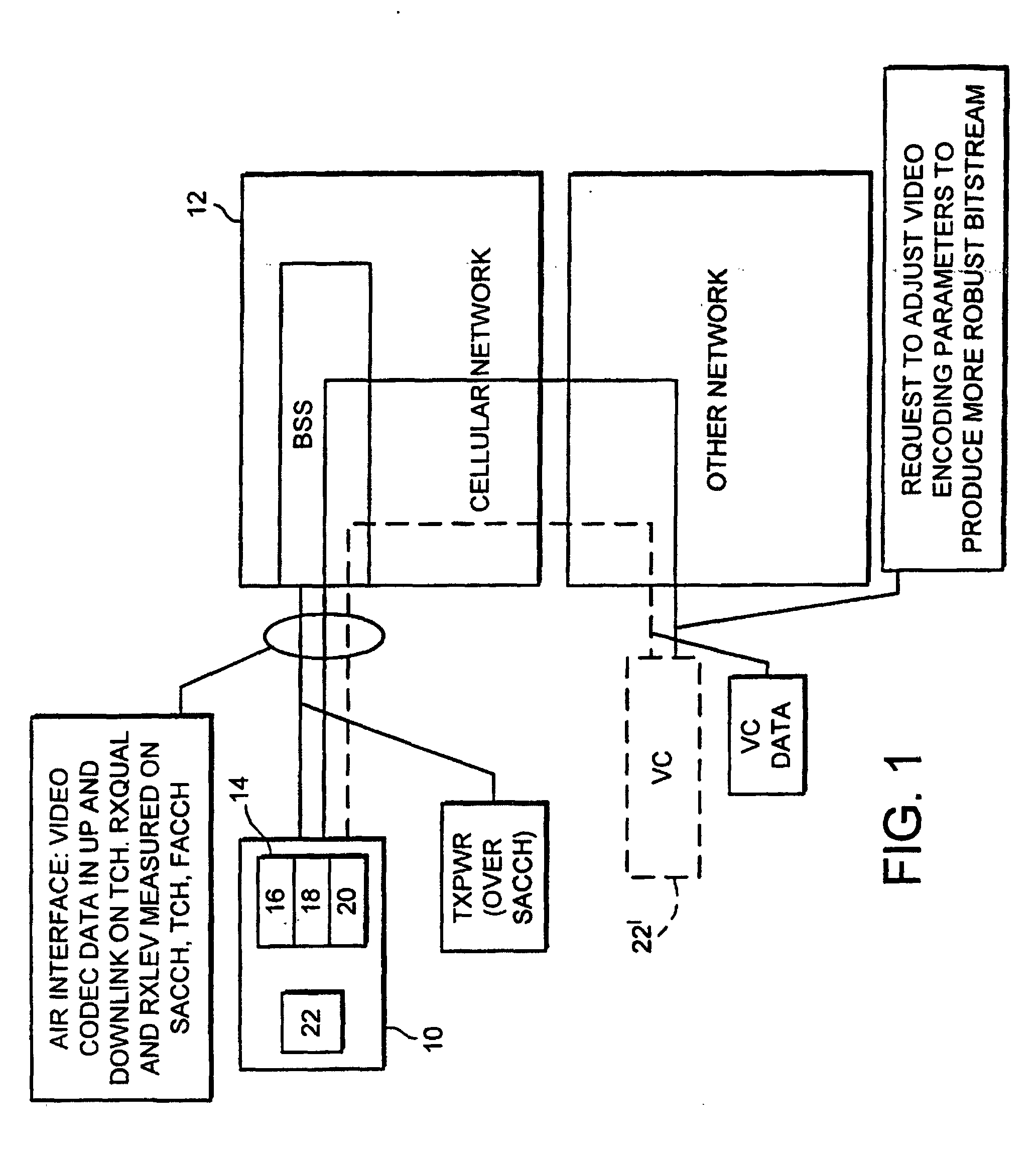
[0023] In the block diagram cellular telephone system shown in Figure 1, a mobile station
10 is linked to operate in a cellular network 12, transferring data and digitised
signals in a two way radio communication link. The cellular network 12 typically comprises
an array of base stations which are linked together either directly or indirectly
via mobile switching centres, and which enable information to be routed between mobile
stations as well as landline telephones.
[0024] The mobile station 10 is equipped with the standard features associated with a mobile
communication device: a keypad for dialling numbers, accepting and terminating a call,
storing telephone numbers, and so on; a microphone and a loudspeaker; an antenna for
radiating electromagnetic waves at transmission frequencies during transmission, and
during reception for converting received electromagnetic waves at reception frequencies
into electrical signals, and an RF block 14 comprising a receiver 16, synthesizers
18 and a transmitter 20. The mobile station 10 is further provided with a video codec
22 which, as explained above, can perform video compression (encode) and/or expansion
(decode) for transmission and reception of video images. A video telephony system
having full functionality also contains other related blocks such as audio codec,
and mulltplexer/demultlplexer which take care of combining the coded video and audio
into a single bitstream and so on.
[0025] An alternative arrangement is shown in dashed lines in Figure 1, in which the video
codec 22' is remote from the mobile station 10. In such a situation, the video codec
communicates (remotely) with the mobile station through the cellular or some other
network.
[0026] Alternatively, it is envisaged that the mobile station may be a radio card and that
the video codec is provided in a computer (e.g. portable computer) to which the radio
card can be connected via, for example, a PCMCIA connection. In this case, instructions
from a mobile station 10 may be sent to the video codec 22' over AT commands and the
data transfer between the video codec and the mobile station may be performed over
a V.80 conncetion.
[0027] It will be apparent that the transfer of video signals between a mobile station and
a cellular network can occur in two directions: in one direction, the network transmits
whilst the mobile station receives, this is known as the down-link direction; in the
other direction, the mobile station transmits whilst the network receives, and this
Is known as the up-link direction. End-to-end use refers to the situation in which
two mobile stations are in communication with one another through the telecommunication
network.
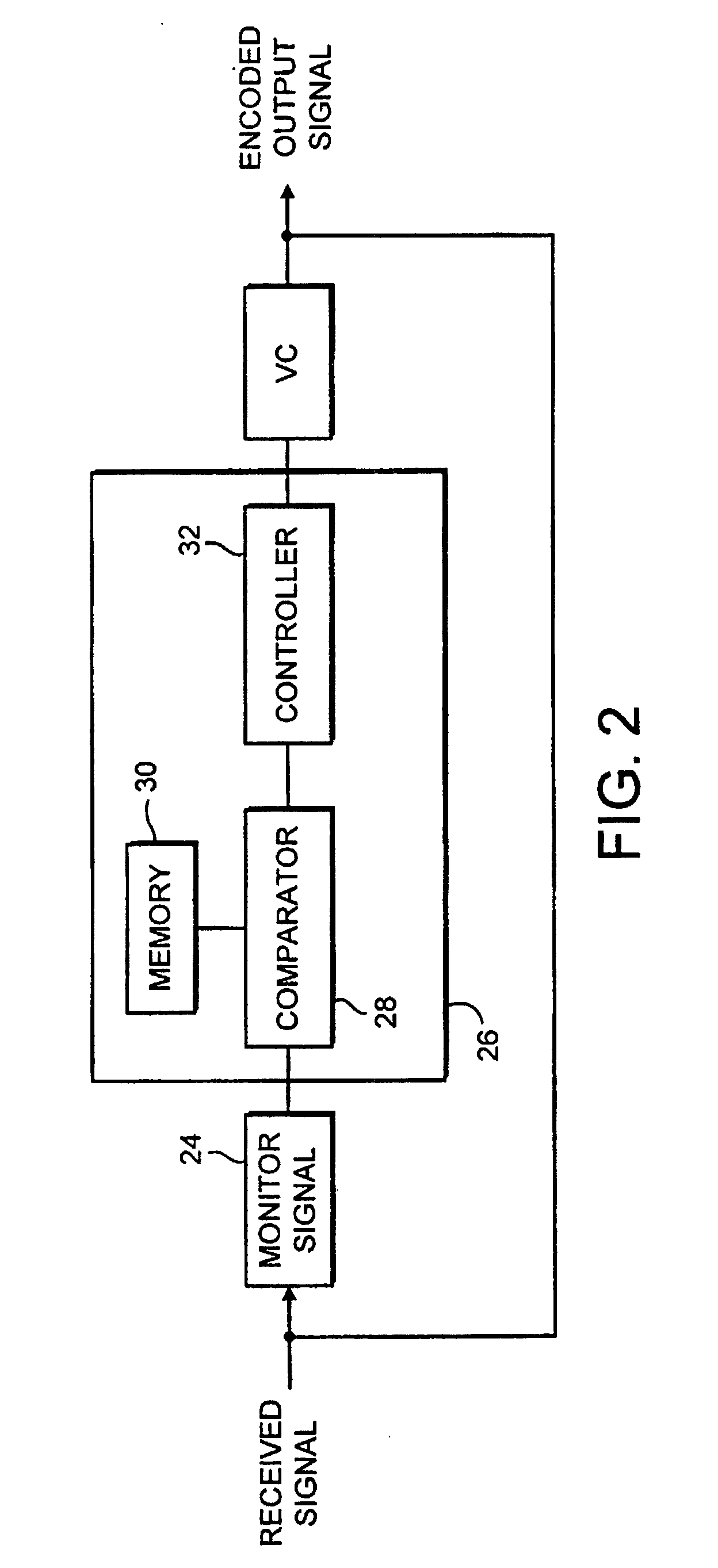
[0028] A first embodiment of the present invention operating in the down-link direction
will be described with reference to Figure 2.
[0029] In down-link mode, the mobile station 10 receives data transmitted by the network
12 and continuously monitors at 24, in the preferred embodiment, the received signal
quality and signal strength. In GSM these requirements are defined in GSM 05.08 and
are used for example for handover decisions. The received signal quality and signal
strength provides an indication of C/I (carrier to interference) and C/N (carrier
to noise ratio).
[0030] In GSM 05.08 the received signal strength (or received signal level) of the serving
base station is denoted by the two parameters: RXLEV_FULL SERVING_CELL and RXLEV_SUB_SERVING_CELL.
The received signal strength is referred to in this text as RXLEV, which may be RXLEV_FULL_SERVING_CELL
or RXLEV_SUB_SERVING_CELL, depending on the use of discontinuous transmission (DTX)
during the call.
[0031] Similarly in GSM 05.08 the received signal quality is denoted by RXQUAL_FULL_SERVING_CELL
and RXQUAL_SUB_SERVING_CELL, depending on the use of DTX, and in this text is referred
to by the term RXQUAL.
[0032] The signal power is measured by the receiver, and it is mapped to RXLEV values as
presented in GSM 05.08. Whilst RXLEV may not always correlate with C/N, a low RXLEV
value indicates low signal strength, hence low C/N on the radio path. High RXLEV does
not necessarily indicate high C/N, because high RXLEV may be generated by high interference
levels as well.
[0033] RXQUAL is an estimate of bit error rate (BER) in the received signal before channel
decoding. Mapping between BER and RXQUAL is described in GSM 05.08. High BER values
are caused either by low C/N or by low C/I, while lower BER values coincide with either
higher C/N or high C/I.
[0034] In the GSM system, RXLEV is usually compared to signal strengths of the neighbouring
base stations and used as the criterion for inter-cell handover.
RXQUAL is typically used as the criterion for intra-cell channel changes.
[0035] In the presented invention, it is possible to detect low C/I and low C/N from RXQUAL
alone, but RXLEV information could also be utilised to improve accuracy.
[0036] The output value of the monitored signal, ie. a value indicative of the received
signal's quality and strength, is fed to a control system 26. It should be noted that
the control system 26 can be part of the mobile station 10, or alternatively it can
be located in the network 12, in which case the monitored signal is transmitted by
the mobile station 10.
[0037] The control system 26 comprises a comparator 28, memory means 30 associated with
the comparator 28, and a controller 32 downstream of the comparator 28. The output
value of the monitored signal is fed into the comparator 28 which compares this value
with values for signal quality and strength taken from the memory means 30. The memory
means 30 contains a store of values for signal quality and strength correlated to
acceptable images when decoded. The store of values includes upper limits and lower
limits of operation, thereby defining preferred operating ranges. These would normally
be factory set but could be user defined. The comparison made in the comparator 28
provides information as to whether the monitored values of the received signal are
within the preferred operating ranges, above them or below them. For example, if transmission
errors are high then the received signal would be relatively weak and the comparator
28, comparing this against stored values, would output a result reflecting this.
[0038] The output from the comparator 28 is fed into the controller 32. On the basis of
the result of the comparator 28, the controller 32 decides whether or not to change
the coding parameters of the transmitting video codec. If the result from the comparator
28 is that the monitored received signal is within its preferred operating range then
the controller 32 directs no changes in the coding parameters. On the other hand,
if the monitored signal is outside its preferred operating range then the controller
32 commands a change in the operation of the video codec. For example, in the case
of high transmission error the controller 32 commands the encoding video codec to
produce a more robust bit stream with more intra-refresh information and/or start
codes. Hence, the quality of the image generated by the decoding video codec will
be much improved. In this way, in down-link mode, the mobile station has adaptive
control of the encoding parameters of the transmitting video codec.
[0039] The transmitting video codec may be located in the network itself, or, in an end-to-end
communication would be located in the transmitting mobile station. One possible means
for the receiving mobile station to command a change in operating performance of the
transmitting video codec in another mobile station is to use H.245 Control Protocol
specification for Multimedia Communication.
[0040] In the latter instance, the command to change the operating performance of the transmitting
video codec is sent from the receiving mobile station to the network, and this command
is then fed by the network to the remote transmitting mobile station. Accordingly,
it is possible for a first mobile station to affect the video coding parameters of
a second mobile station by monitoring the condition of the radio link on its side
of the network and providing feedback information thereon.
[0041] In the up-link direction in which the mobile station transmits and the cellular network
receives, a similar process may be employed whereby the signal received at the base
station is used as an indication of the quality of the link, and which is monitored
and then fed back to the mobile station for modifying the operation of the video codec.
[0042] However, currently in GSM it is not possible for the mobile station directly to obtain
information about the receive quality levels measured at the base station. Nor is
this information delivered from the cellular network to the mobile station. Thus in
order to obtain a measure of the quality of the up-link connection, use is made of
the up-link power level. In GSM this is defined in GSM 05.08. The up-link power level
is a parameter that is commanded by the network. So at times when the signal level
and quality of the up-link transmission deteriorates, the network commands the transmission
power of the mobile station to be increased. This request for higher transmission
power is discerned by the mobile station which in turn triggers an increase in the
intra-refresh and start code parameters of the video codec, provided that the change
in power level is deemed to be high enough. In this regard, the mobile station is
provided with look-up tables stored in the memory means which contain information
on the correlation between transmission power levels and the appropriate density of
coding parameters in a coding algorithm.
[0043] Returning to Figure 1, TXPWR refers to the regularly transmitted network request
to increase or decrease transmitter power. This is defined in GSM 05.08 as parameter
MS_TXPWR_REQUEST. Alternatively or in addition, use could also be made of other power
level related information sent by the network, such as power level commands in connection
with handover.
[0044] The box in Figure 1 labelled 'other network' can also be an ascending network ISDN,
PSTN or even the same network where the mobile station with the video codec is connected.
As mentioned above, it will be appreciated that received signal quality and received
signal strength could also be used in the network side with a link between the network
and video codec in the mobile station. In principle, it is possible to store the intra-frames
in a dedicated memory unit in the network for example in the base station. Stored
frames could then be retransmitted whenever the radio interface parameters indicated
that the C/I or C/N ratio is low.
[0045] Whilst the invention has been described in the context of circuit switched transparent
mode, the invention can be applied also in packet switched unacknowledged mode. The
invention as such can be used in packet switched acknowledged and circuit switched
non transparent mode. Of course in these cases there is the general penalty of harmful
retransmission in a real time service. However in principal the invention itself is
applicable irrespective of the way the radio interface is implemented. In addition
to RXQUAL and RXLEV other parameters also can be used to determine the quality of
the connection. These may include retransmission of signalling frames, number of lost
frames, number of retransmissions of data frames on RLC layer in GPRS acknowledged
mode. In GPRS the variance of the signal level (BL_VAR SIGN_VAR) could be one of the
parameters to be measured. In addition, a further parameter which may be monitored
may be that of the video signal itself. For example bit error rate in the received
video stream as monitored by a demulitplexer in a multi-media terminal performing
a cyclic redundancy check may be used as an indication for controlling the transmitting
video codec.
[0046] Optionally, when an intra-frame is being transmitted by a mobile station and hand
over takes place, the intra-frame can be retransmitted because the first one may be
lost due to the hand over. The same also applies to other changes in the channel mode
for example between GMSK and EDGE modulations. In down-link, the mobile station may
request an extra intra-frame after every hand over or channel mode change because
an intra-frame may have been lost in the down link direction.
[0047] It is envisaged that the present invention will be particularly beneficial in cases
where the variation in the radio parameters becomes large. For example this happens
in GSM with EDGE (Enhanced Data rates for GSM Evolution), because in EDGE the data
quality may vary significantly. Also very frequent channel coding or modulation changes
characteristic of EDGE destroy frames, thus it is advantageous to increase the rate
of intra-refresh and/or start code information when required.
[0048] The present invention may be embodied in other specific forms without departing from
its essential attributes. Accordingly reference should be made to the appended claims
and other general statement's herein rather than to the foregoing specific description
as indicating the scope of invention.
[0049] Furthermore, each feature disclosed in this specification (which term includes the
claims) and/or shown in the drawings may be incorporated in the invention independently
of other disclosed and/or illustrated features. In this regard, the invention includes
any novel feature or combination of features disclosed herein either explicitly or
any generalisation thereof irrespective of whether or not it relates to the claimed
invention or mitigates any or all of the problems addressed.
[0050] The appended abstract as filed herewith is included in the specification by reference.
1. A method of controlling the encoding of a digital video signal by a video encoder
(22, 22'), in which the digital video signal is encoded by the video encoder (22,
22') and transmitted by means of a radio frequency communication signal by a first
radio communication device (10, 12) to a second radio communication device, said radio
frequency communication signal being received at the second radio communication device
(10, 12),
characterised in that the method comprises:
- monitoring at least one parameter indicative of a property of the radio frequency
communication signal received at the second radio communication device (10, 12);
- responsive to said at least one monitored parameter, forming a feedback signal for
controlling at least one encoding parameter of the video encoder (22, 22');
- transmitting said feedback signal from said second radio communication device (10,
12) to said first radio communication device (10, 12);
- receiving said feedback signal at said first radio communication device (10, 12);
and
- providing said feedback signal received at said first radio communication device
to said video encoder (22, 22') to control the encoding of said digital video signal.
2. A method according to claim 1, characterised in that said at least one parameter indicative of a property of the radio frequency communication
signal monitored at the second radio communication device is a measure of received
signal quality (RXQUAL).
3. A method according to claim 1 or 2, characterised in that said at least one parameter indicative of a property of the radio frequency communication
signal monitored at the second radio communication device is a measure of received
signal strength (RXLEV).
4. A method according to any of claims 1, 2 or 3, characterised in that the video encoder (22, 22') is remote from the first radio communication device (10,
12).
5. A method according to any of claims 1, 2 or 3, characterised in that the video encoder (22, 22') is located in the first radio communication device (10,
12).
6. A method according to claim 4, characterised in that the video encoder (22, 22') is located in a personal computer in connection with
said first radio communication device (10, 12).
7. A method according to any of claims 1 to 4, characterised in that the video encoder (22, 22') is located in connection with a third radio communication
device (10, 12), said first radio communication device is a radio communication network
and said second radio communication device and said third radio communication devices
are selected from a group comprising: a portable radio communication apparatus; and
a radio card for use in connection with a personal computer.
8. A method according to claim 7, characterised in that said digital video signal is encoded by said video encoder (22, 22') and is transmitted
as a radio frequency communication signal from said third radio communication device
(10, 12) to said first radio communication device (10, 12) and further from said first
radio communication device (10, 12) to said second radio communication device (10,
12).
9. A method according to claim 8, characterised in that said feedback signal responsive to said at least one monitored parameter transmitted
from said second radio communication device (10,12) to said first radio communication
device (10, 12) is further transmitted from said first radio communication device
(10, 12) to said third radio communication device (10, 12).
10. A method according to claim 9, characterised in that transmission of said feedback signal responsive to said at least one monitored parameter
from said second radio communication device (10, 12) to said first radio communication
device (10, 12) and further from said first radio communication device (10, 12) to
said third radio communication device (10, 12) is performed by an end-to-end control
protocol.
11. A method according to claim 10, characterised in that said end-to-end control protocol is an H.245 control protocol.
12. A method according to any of claims 1 to 6, characterised in that the first radio communication device (10, 12) is selected from a group comprising:
a portable radio communication apparatus; and a radio card for use in connection with
a personal computer and the second communication device (10, 12) is a radio communication
network.
13. A method according to any of claims 1 to 6, characterised in that the first radio communication device (10, 12) is a radio communication network and
the second radio communication device (10, 12) is selected from a group comprising:
a portable radio communication apparatus; and a radio card for use in connection with
a personal computer.
14. A method according to any preceding claim characterised in that said at least one encoding parameter of the video encoder (22, 22') controls the
frequency of intra-refresh data in the encoded video data.
15. A method according to any preceding claim characterised in that said at least one encoding parameter of the video encoder (22, 22') controls the
frequency of start codes in the encoded video data.
16. An apparatus (26) for controlling the encoding of a digital video signal by a video
encoder (22, 22'), said digital video signal being encoded by the video encoder (22,
22') and transmitted by means of a radio frequency communication signal by a first
radio communication device (10, 12) to a second radio communication device (10, 12),
said radio frequency communication signal being received at the second radio communication
device (10, 12),
characterised in that said apparatus (26) is located in the second radio communication device (10, 12)
and comprises:
- means (24) for monitoring at least one parameter indicative of a property of the
radio frequency communication signal received at the second radio communication device
(10, 12);
- means (28, 30, 32) for forming a feedback signal responsive to said at least one
monitored parameter for controlling at least one encoding parameter of the video encoder
(22, 22').
17. An apparatus (26) according to claim 16, characterised in that it comprises means (24) for measuring a signal quality (RXQUAL) of the radio frequency
communication signal received at said second radio communication device (10, 12) as
a parameter indicative of a property of the radio frequency communication signal.
18. An apparatus (26) according to claim 16 or 17, characterised in that it comprises means (24) for measuring a signal strength (RXLEV) of the radio frequency
communication signal received at said second radio communication device (10, 12) as
a parameter indicative of a property of the radio frequency communication signal.
19. A system (10, 12, 24, 26, 28, 30, 32) for controlling the encoding of a digital video
signal by a video encoder (22, 22'), said digital video signal being encoded by the
video encoder (22, 22') and transmitted by means of a radio frequency communication
signal by a first radio communication device (10, 12) to a second radio communication
device (10, 12), said radio frequency communication signal being received at the second
radio communication device (10, 12),
characterised in that the system (10, 12, 24, 26, 28, 30, 32) comprises:
- means (24) for monitoring at least one parameter indicative of a property of the
radio frequency communication signal received at the second radio communication device
(10, 12);
- means (28, 30, 32) for forming a feedback signal responsive to said at least one
monitored parameter for controlling at least one encoding parameter of the video encoder
(22, 22');
- means (20, BSS) for transmitting said feedback signal from said second radio communication
device (10,12) to said first radio communication device (10, 12);
- means (16, BSS) for receiving said feedback signal at said first radio communication
device (10, 12); and
- means for providing said feedback signal received at said first radio communication
device to said video encoder (22, 22') to control the encoding of said digital video
signal.
20. A system (10, 12, 24, 26, 28, 30, 32) according to claim 19, characterised in that it comprises means (24) for measuring a signal quality (RXQUAL) of the radio frequency
communication signal received at said second radio communication device (10, 12) as
a parameter indicative of a property of the radio frequency communication signal.
21. A system (10, 12, 24, 26, 28, 30, 32) according to claim 19 or 20, characterised in that it comprises means (24) for measuring a signal strength (RXLEV) of the radio frequency
communication signal received at said second radio communication device (10, 12) as
a parameter indicative of a property of the radio frequency communication signal.
22. A system (10, 12, 24, 26, 28, 30, 32) according to any of claims 19, 20 or 21, characterised in that the video encoder (22, 22') is remote from the first radio communication device (10,
12).
23. A system (10, 12, 24, 26, 28, 30, 32) according to any of claims 19, 20 or 21, characterised in that the video encoder (22, 22') is located in the first radio communication device (10,
12).
24. A system (10, 12, 24, 26, 28, 30, 32) according to claim 22, characterised in that the video encoder (22, 22') is located in a personal computer in connection with
said first radio communication device (10, 12).
25. A system (10, 12, 24, 26, 28, 30, 32) according to any of claims 19 to 22, characterised in that it further comprises a third radio communication device (10, 12), said video encoder
(22, 22') is located in connection with said third radio communication device (10,
12), said first radio communication device (10, 12) is a radio communication network
and said second radio communication device (10, 12) and said third radio communication
device (10, 12) are selected from a group comprising: a portable radio communication
apparatus; and a radio card for use in connection with a personal computer.
26. A system (10, 12, 24, 26, 28, 30, 32) according to claim 25, characterised in that said third radio communication device (10, 12) comprises means (20) for transmitting
a digital video signal encoded by said video encoder (22, 22') as a radio frequency
communication signal to said first radio communication device (10, 12) and said first
radio communication device (10, 12) comprises means (BSS) for transmitting the digital
video signal encoded by said video encoder (22, 22') as a radio frequency communication
signal to said second radio communication device (10, 12).
27. A system (10, 12, 24, 26, 28, 30, 32) according to claim 26, characterised in that said first radio communication device (10, 12) comprises means for transmitting (20,
BSS) said feedback signal responsive to said at least one monitored parameter transmitted
from said second radio communication device (10, 12) to said first radio communication
device (10, 12) further from said first radio communication device (10, 12) to said
third radio communication device (10, 12).
28. A system (10, 12, 24, 26, 28, 30, 32) according to claim 27, characterised in that transmission of said feedback signal responsive to said at least one monitored parameter
from said second radio communication device (10, 12) to said first radio communication
device (10, 12) and further from said first radio communication device (10, 12) to
said third radio communication device (10, 12) is arranged to be performed by an end-to-end
control protocol.
29. A system (10, 12, 24, 26, 28, 30, 32) according to claim 28, characterised in that said end-to-end control protocol is an H.245 control protocol.
30. A system according to any of claims 19 to 24, characterised in that the first radio communication device (10, 12) is selected from a group comprising:
a portable radio communication apparatus; and a radio card for use in connection with
a personal computer and the second communication device (10, 12) is a radio communication
network.
31. A system (10, 12, 24, 26, 28, 30, 32) according to any of claims 19 to 24, characterised in that the first radio communication device (10, 12) is a radio communication network and
the second radio communication device (10, 12) is selected from a group comprising:
a portable radio communication apparatus; and a radio card for use in connection with
a personal computer.
32. A system (10, 12, 24, 26, 28, 30, 32) according to any of claims 19 to 31 characterised in that said at least one encoding parameter of the video encoder (22, 22') is arranged to
control the frequency of intra-refresh data in the encoded video data.
33. A system (10, 12, 24, 26, 28, 30, 32) according to any of claims 19 to 32 characterised in that said at least one encoding parameter of the video encoder (22, 22') is arranged to
control the frequency of start codes in the encoded video data.
34. A method of controlling the encoding of a digital video signal, in which said digital
video signal is encoded by a video encoder (22, 22') and transmitted by means of a
radio frequency communication signal by a first radio communication device (10, 12),
said radio frequency communication signal being received by a second radio communication
device (10, 12),
characterised in that the method comprises:
- monitoring at least one parameter indicative of a property of the radio frequency
communication signal transmitted from the first radio communication device (10, 12);
- responsive to said at least one monitored parameter, forming a feedback signal for
controlling at least one encoding parameter of the video encoder (22, 22');
- providing said feedback signal to said video encoder (22, 22') to control the encoding
of said digital video signal.
35. A method according to claim 34, characterised in that said at least one parameter indicative of a property of the radio frequency communication
signal transmitted from the first radio communication device (10, 12) is a measure
of transmitted signal power (TXPWR).
36. A method according to claim 34 or 35, characterised in that said at least one parameter indicative of a property of the radio frequency communication
signal transmitted from the first radio communication device (10, 12) is a power control
command (TXPWR) received at said first radio communication device (10, 12).
37. A method according to any of claims 34, 35 or 36, characterised in that the video encoder (22, 22') is remote from the first radio communication device (10,
12).
38. A method according to claim 37, characterised in that the video encoder (22, 22') is located in a personal computer in connection with
said first radio communication device (10, 12).
39. A method according to any of claims 34, 35 or 36, characterised in that the video encoder (22, 22') is located in the first radio communication device (10,
12).
40. A method according to any of claims 34 to 39, characterised in that the first radio communication device (10, 12) is selected from a group comprising:
a portable radio communication apparatus; and a radio card for use in connection with
a personal computer and the second communication device (10, 12) is a radio communication
network.
41. A method according to any of claims 34 to 39, characterised in that the first radio communication device (10, 12) is a radio communication network and
the second radio communication device (10, 12) is selected from a group comprising:
a portable radio communication apparatus; and a radio card for use in connection with
a personal computer.
42. A method according to any of claims 34-41 characterised in that said at least one encoding parameter of the video encoder (22, 22') controls the
frequency of intra-refresh data in the encoded video data.
43. A method according to any of claims 34-42 characterised in that said at least one encoding parameter of the video encoder (22, 22') controls the
frequency of start codes in the encoded video data.
44. An apparatus (26) for controlling the encoding of a digital video signal, said digital
video signal being encoded by a video encoder (22, 22') and transmitted by means of
a radio frequency communication signal by a first radio communication device (10,
12), said radio frequency communication signal being received by a second radio communication
device (10, 12),
characterised in that said apparatus (26) is located In the first radio communication device (10, 12) and
comprises:
- means (24) for monitoring at least one parameter indicative of a property of the
radio frequency communication signal transmitted from the first radio communication
device (10, 12); and
- means (28, 30, 32) for forming a feedback signal responsive to said at least one
monitored parameter for controlling at least one encoding parameter of the video encoder
(22, 22').
45. An apparatus (26) according to claim 44, characterised in that said means (24) for monitoring at least one parameter indicative of a property of
the radio frequency communication signal transmitted from the first radio communication
device (10, 12) comprises means for measuring a transmission power (TXPWR) of said
radio frequency communication signal.
46. An apparatus (26) according to claim 44 or 45, characterised in that said means (24) for monitoring at least one parameter indicative of a property of
the radio frequency communication signal transmitted from the first radio communication
device (10, 12) comprises means responsive to a power control command (TXPWR) received
at said first radio communication device (10, 12).
47. A system (10, 12, 24, 26, 28, 30, 32) for controlling the encoding of a digital video
signal, said digital video signal being encoded by a video encoder (22, 22') and transmitted
by means of a radio frequency communication signal by a first radio communication
device (10, 12), said radio frequency communication signal being received by a second
radio communication device (10, 12),
characterised in that the system (10, 12, 24, 26, 28, 30, 32) comprises:
- means (24) for monitoring at least one parameter indicative of a property of the
radio frequency communication signal transmitted from the first radio communication
device (10, 12);
- means (26, 28, 30, 32) for forming a feedback signal responsive to said at least
one monitored parameter indicative of a property of the radio frequency communication
signal for controlling at least one encoding parameter of the video encoder (22, 22');
and
- means for providing said feedback signal to said video encoder (22, 22') to control
the encoding of said digital video signal.
48. A system (10, 12, 24, 26, 28, 30, 32) according to claim 47, characterised in that said means (24) for monitoring at least one parameter indicative of a property of
the radio frequency communication signal transmitted from the first radio communication
device (10, 12) comprises means for measuring a transmission power (TXPWR) of said
radio frequency communication signal.
49. A system (10, 12, 24, 26, 28, 30, 32) according to claim 47 or 48, characterised in that said means (24) for monitoring at least one parameter indicative of a property of
the radio frequency communication signal transmitted from the first radio communication
device (10, 12) comprises means responsive to a power control command (TXPWR) received
at said first radio communication device (10, 12).
50. A system (10, 12, 24, 26, 28, 30, 32) according to claim 47, 48 or 49, characterised in that the first radio communication device (10, 12) is selected from a group comprising:
a portable radio communication apparatus; and a radio card for use in connection with
a personal computer and the second communication device (10, 12) is a radio communication
network.
51. A system (10, 12, 24, 26, 28, 30, 32) according to any of claims 47 to 50 characterised in that said at least one encoding parameter of the video encoder (22, 22') is arranged to
control the frequency of intra-refresh data in the encoded video data.
52. A system (10, 12, 24, 26, 28, 30, 32) according to any of claims 47 to 51 characterised in that said at least one encoding parameter of the video encoder (22, 22') is arranged to
control the frequency of start codes in the encoded video data.
53. A mobile terminal comprising control means for controlling the encoding of a digital
video signal being encoded by a video encoder (22, 22') and transmitted as a radio
frequency communication signal by a second radio communication device (10, 12) to
said mobile terminal, said radio frequency communication signal being received at
said mobile terminal,
characterised in that said control means cormprises:
- means (24) for monitoring at least one parameter indicative of a property of the
radio frequency communication signal received at the mobile terminal;
- means (28, 30, 32) for forming a signal responsive to said at least one monitored
parameter for controlling at least one encoding parameter of the video encoder (22,
22').
54. A mobile terminal according to claim 53, characterised in that the control means (24) comprises means for measuring a signal quality (RXQUAL) of
the radio frequency communication signal received at the mobile terminal as a parameter
indicative of a property of the radio frequency communication signal.
55. A mobile terminal according to claim 53 or 54, characterised in that the control means comprises means for measuring a signal strength (RXLEV) of the
radio frequency communication signal received at the mobile terminal as a parameter
indicative of a property of the radio frequency communication signal.
56. A mobile terminal comprising control means for controlling the encoding of a digital
video signal, said digital video signal being encoded by a video encoder (22, 22')
and transmitted as a radio frequency communication signal by said mobile terminal,
said radio frequency communication signal being received by a second radio communication
device,
characterised in that said control means comprises:
- means (24) for monitoring at least one parameter indicative of a property of the
radio frequency communication signal transmitted from the mobile terminal; and
- means (28, 30, 32) for forming a feedback signal responsive to said at least one
monitored parameter for controlling at least one encoding parameter of the video encoder
(22,22').
57. A mobile terminal according to claim 56, characterised in that said means (24) for monitoring at least one parameter indicative of a property of
the radio frequency communication signal transmitted from the mobile terminal comprises
means for measuring a transmission power (TXPWR) of said radio frequency communication
signal.
58. A mobile terminal according to claim 56 or 57, characterised In that said means (24) for monitoring at least one parameter indicative of a property of
the radio frequency communication signal transmitted from the mobile terminal comprises
means responsive to a power control command (TXPWR) received at said mobile terminal.
59. A digital video encoder (22,22') comprising encoder means configured to operate in
accordance with an encoding procedure so as to provide encoded video data for transmission
by means of a radio communication signal by a first radio communication device (10,12)
to a second radio communication device (10,12),
the encoder means being operable to respond to feedback signals based on at least
one monitored parameter indicative of a property of the radio frequency communication
signal so as to control the encoding procedure used by the digital video encoder for
encoding video data.
1. Verfahren zum Steuern der Codierung eines digitalen Videosignals durch einen Videocodierer
(22, 22'), wobei das digitale Videosignal durch den Videocodierer (22, 22') codiert
und mit Hilfe eines Hochfrequenz-Kommunikationssignals durch eine erste Funk-Kommunikationsvorrichtung
(10, 12) an eine zweite Funk-Kommunikationsvorrichtung gesendet wird, wobei das Hochfrequenz-Kommunikationssignal
an der zweiten Funk-Kommunikationsvorrichtung (10, 12) empfangen wird,
dadurch gekennzeichnet, daß das Verfahren umfaßt:
- Überwachen wenigstens eines Parameters, der eine Eigenschaft des Hochfrequenz-Kommunikationssignals,
das an der zweiten Funk-Kommunikationsvorrichtung (10, 12) empfangen wird, angibt;
- in Reaktion auf den wenigstens einen überwachten Parameter Bilden eines Rückführungssignals
zum Steuern des wenigstens einen Codierparameters des Videocodierers (22, 22');
- Senden des Rückführungssignals von der zweiten Funk-Kommunikationsvorrichtung (10,
12) an die erste Funk-Kommunikationsvorrichtung (10, 12);
- Empfangen des Rückführungssignals an der ersten Funk-Kommunikationsvorrichtung (10,
12); und
- Liefern des an der ersten Funk-Kommunikationsvorrichtung empfangenen Rückführungssignals
an den Videocodierer (22, 22'), um das Codieren des digitalen Videosignals zu steuern.
2. Verfahren nach Anspruch 1, dadurch gekennzeichnet, daß der wenigstens eine Parameter, der eine Eigenschaft des an der zweiten Funk-Kommunikationsvorrichtung
überwachten Hochfrequenz-Kommunikationssignals angibt, ein Maß der Qualität des Empfangssignals
(RXQUAL) ist.
3. Verfahren nach Anspruch 1 oder 2, dadurch gekennzeichnet, daß der wenigstens eine Parameter, der eine Eigenschaft des an der zweiten Funk-Kommunikationsvorrichtung
überwachten Hochfrequenz-Kommunikationssignals angibt, ein Maß der Stärke des Empfangssignals
(RXLEV) ist.
4. Verfahren nach einem der Ansprüche 1, 2 oder 3, dadurch gekennzeichnet, daß der Videocodierer (22, 22') von der ersten Funk-Kommunikationsvorrichtung (10, 12)
entfernt ist.
5. Verfahren nach einem der Ansprüche 1, 2 oder 3, dadurch gekennzeichnet, daß der Videocodierer (22, 22') in der ersten Funk-Kommunikationsvorrichtung (10, 12)
angeordnet ist.
6. Verfahren nach Anspruch 4, dadurch gekennzeichnet, daß der Videocodierer (22, 22') in einem Personalcomputer, der mit der ersten Funk-Kommunikationsvorrichtung
(10, 12) verbunden ist, angeordnet ist.
7. Verfahren nach einem der Ansprüche 1 bis 4, dadurch gekennzeichnet, daß der Videocodierer (22, 22') in Verbindung mit einer dritten Funk-Kommunikationsvorrichtung
(10, 12) angeordnet ist, wobei die erste Funk-Kommunikationsvorrichtung ein Funk-Kommunikationsnetz
ist und die zweiten und die dritten Funk-Kommunikationsvorrichtungen aus einer Gruppe
ausgewählt sind, die umfaßt: ein tragbares Funk-Kommunikationsgerät; und eine Funkkarte
zur Verwendung in Verbindung mit einem Personalcomputer.
8. Verfahren nach Anspruch 7, dadurch gekennzeichnet, daß das digitale Videosignal durch den Videocodierer (22, 22') codiert wird und als ein
Hochfrequenz-Kommunikationssignal von der dritten Funk-Kommunikationsvorrichtung (10,
12) an die erste Funk-Kommunikationsvorrichtung (10, 12) und weiter von der ersten
Funk-Kommunikationsvorrichtung (10, 12) an die zweite Funk-Kommunikationsvorrichtung
(10, 12) gesendet wird.
9. Verfahren nach Anspruch 8, dadurch gekennzeichnet, daß das Rückführungssignal in Reaktion auf den überwachten Parameter, der von der zweiten
Funk-Kommunikationsvorrichtung (10, 12) an die erste Funk-Kommunikationsvorrichtung
(10, 12) gesendet wird, weiter von der ersten Funk-Kommunikationsvorrichtung (10,
12) an die dritte Funk-Kommunikationsvorrichtung (10, 12) gesendet wird.
10. Verfahren nach Anspruch 9, dadurch gekennzeichnet, daß die Übertragung des Rückführungssignals in Reaktion auf den wenigstens einen überwachten
Parameter von der zweiten Funk-Kommunikationsvorrichtung (10, 12) an die erste Funk-Kommunikationsvorrichtung
(10, 12) und weiter von der ersten Funk-Kommunikationsvorrichtung (10, 12) an die
dritte Funk-Kommunikationsvorrichtung (10, 12) durch ein Ende-zu-Ende-Steuerprotokoll
durchgeführt wird.
11. Verfahren nach Anspruch 10, dadurch gekennzeichnet, daß das Ende-zu-Ende-Steuerprotokoll ein Steuerprotokoll H.245 ist.
12. Verfahren nach einem der Ansprüche 1 bis 6, dadurch gekennzeichnet, daß die erste Funk-Kommunikationsvorrichtung (10, 12) aus einer Gruppe ausgewählt ist,
die umfaßt: ein tragbares Funk-Kommunikationsgerät; und eine Funkkarte zur Verwendung
in Verbindung mit einem Personalcomputer, und daß die zweite Funk-Kommunikationsvorrichtung
(10, 12) ein Funk-Kommunikationsnetz ist.
13. Verfahren nach einem der Ansprüche 1 bis 6, dadurch gekennzeichnet, daß die erste Funk-Kommunikationsvorrichtung (10, 12) ein Funk-Kommunikationsnetz ist
und die zweite Funk-Kommunikationsvorrichtung (10, 12) aus einer Gruppe ausgewählt
ist, die umfaßt: ein tragbares Funk-Kommunikationsgerät; und eine Funkkarte zur Verwendung
in Verbindung mit einem Personalcomputer.
14. Verfahren nach einem der vorhergehenden Ansprüche, dadurch gekennzeichnet, daß wenigstens einer der Codierparameter des Videocodierers (22, 22') die Häufigkeit
der Daten zur Internauffrischung in den codierten Videodaten steuert.
15. Verfahren nach einem der vorhergehenden Ansprüche, dadurch gekennzeichnet, daß wenigstens einer der Codierparameter des Videocodierers (22, 22') die Häufigkeit
von Startcodes in den codierten Videodaten steuert.
16. Gerät (26) zum Steuern der Codierung eines digitalen Videosignals durch einen Videocodierer
(22, 22'), wobei das digitale Videosignal durch den Videocodierer (22, 22') codiert
wird und mit Hilfe eines Hochfrequenz-Kommunikationssignals durch eine erste Funk-Kommunikationsvorrichtung
(10, 12) an eine zweite Funk-Kommunikationsvorrichtung (10, 12) gesendet wird, wobei
das Hochfrequenz-Kommunikationssignal an der zweiten Funk-Kommunikationsvorrichtung
(10, 12) empfangen wird,
dadurch gekennzeichnet, daß das Gerät (26) in der zweiten Funk-Kommunikationsvorrichtung (10, 12) angeordnet
ist und umfaßt:
- Mittel (24) zum Überwachen wenigstens eines Parameters, der eine Eigenschaft des
an der zweiten Funk-Kommunikationsvorrichtung (10, 12) empfangenen Hochfrequenz-Kommunikationssignals
angibt;
- Mittel (28, 30, 32) zum Bilden eines Rückführungssignals in Reaktion auf den wenigstens
einen überwachten Parameter zum Steuern des wenigstens einen Codierparameters des
Videocodierers (22, 22').
17. Gerät (26) nach Anspruch 16, dadurch gekennzeichnet, daß es Mittel (24) umfaßt zum Messen einer Signalqualität (RXQUAL) des an der zweiten
Funk-Kommunikationsvorrichtung (10, 12) empfangenen Hochfrequenz-Kommunikationssignals
als ein Parameter, der eine Eigenschaft des Hochfrequenz-Kommunikationssignals angibt.
18. Gerät (26) nach Anspruch 16 oder 17, dadurch gekennzeichnet, daß es Mittel (24) umfaßt zum Messen einer Signalstärke (RXLEV) des an der zweiten Funk-Kommunikationsvorrichtung
(10, 12) empfangenen Hochfrequenz-Kommunikationssignals als ein Parameter, der eine
Eigenschaft des Hochfrequenz-Kommunikationssignals angibt.
19. System (10, 12, 24, 26, 28, 30, 32) zum Steuern der Codierung eines digitalen Videosignals
durch einen Videocodierer (22, 22'), wobei das digitale Videosignal durch den Videocodierer
(22, 22') codiert wird und mit Hilfe eines Hochfrequenz-Kommunikationssignals durch
eine erste Funk-Kommunikationsvorrichtung (10, 12) an eine zweite Funk-Kommunikationsvorrichtung
(10, 12) gesendet wird, wobei das Hochfrequenz-Kommunikationssignal an der zweiten
Funk-Kommunikationsvorrichtung (10, 12) empfangen wird,
dadurch gekennzeichnet, daß das System (10, 12, 24, 26, 28, 30, 32) umfaßt:
- Mittel (24) zum Überwachen des wenigstens einen Parameters, der eine Eigenschaft
des an der zweiten Funk-Kommunikationsvorrichtung (10, 12) empfangenen Hochfrequenz-Kommunikationssignals
angibt;
- Mittel (28, 30, 32) zum Bilden eines Rückführungssignals in Reaktion auf den wenigstens
einen überwachten Parameter zum Steuern des wenigstens einen Codierparameters des
Videocodierers (22, 22');
- Mittel (20, BSS) zum Senden des Rückführungssignals von der zweiten Funk-Kommunikationsvorrichtung
(10, 12) an die erste Funk-Kommunikationsvorrichtung (10, 12);
- Mittel (16, BSS) zum Empfangen des Rückführungssignals an der ersten Funk-Kommunikationsvorrichtung
(10, 12); und
- Mittel zum Liefern des an der ersten Funk-Kommunikationsvorrichtung (10, 12) empfangenen
Rückführungssignals an den Videocodierer (22, 22') zum Steuern der Codierung des digitalen
Videosignals.
20. System (10, 12, 24, 26, 28, 30, 32) nach Anspruch 19, dadurch gekennzeichnet, daß es Mittel (24) umfaßt zum Messen einer Signalqualität (RXQUAL) des an der zweiten
Funk-Kommunikationsvorrichtung (10, 12) empfangenen Hochfrequenz-Kommunikationssignals
als ein Parameter, der eine Eigenschaft des Hochfrequenz-Kommunikationssignals angibt.
21. System (10, 12, 24, 26, 28, 30, 32) nach Anspruch 19 oder 20, dadurch gekennzeichnet, daß es Mittel (24) umfaßt zum Messen einer Signalstärke (RXLEV) des an der zweiten Funk-Kommunikationsvorrichtung
(10, 12) empfangenen Hochfrequenz-Kommunikationssignals als ein Parameter, der eine
Eigenschaft des Hochfrequenz-Kommunikationssignals angibt.
22. System (10, 12, 24, 26, 28, 30, 32) nach einem der Ansprüche 19, 20 oder 21, dadurch gekennzeichnet, daß der Videocodierer (22, 22') von der ersten Funk-Kommunikationsvorrichtung (10, 12)
entfernt ist.
23. System (10, 12, 24, 26, 28, 30, 32) nach einem der Ansprüche 19, 20 oder 21, dadurch gekennzeichnet, daß der Videocodierer (22, 22') in der ersten Funk-Kommunikationsvorrichtung (10, 12)
angeordnet ist.
24. System (10, 12, 24, 26, 28, 30, 32) nach Anspruch 22, dadurch gekennzeichnet, daß der Videocodierer (22, 22') in einem Personalcomputer, der mit der ersten Funk-Kommunikationsvorrichtung
(10, 12) in Verbindung steht, angeordnet ist.
25. System (10, 12, 24, 26, 28, 30, 32) nach einem der Ansprüche 19 bis 22, dadurch gekennzeichnet, daß es ferner eine dritte Funk-Kommunikationsvorrichtung (10, 12) umfaßt, wobei der Videocodierer
(22, 22') in Verbindung mit der dritten Funk-Kommunikationsvorrichtung (10, 12) angeordnet
ist, wobei die erste Funk-Kommunikationsvorrichtung (10, 12) ein Funk-Kommunikationsnetz
ist und die zweite Funk-Kommunikationsvorrichtung (10, 12) und die dritte Funk-Kommunikationsvorrichtung
(10, 12) aus einer Gruppe ausgewählt sind, die umfaßt: ein tragbares Funk-Kommunikationsgerät;
und eine Funkkarte zur Verwendung in Verbindung mit einem Personalcomputer.
26. System (10, 12, 24, 26, 28, 30, 32) nach Anspruch 25, dadurch gekennzeichnet, daß die dritte Funk-Kommunikationsvorrichtung (10, 12) Mittel (20) zum Senden eines durch
den Videocodierer (22, 22') codierten digitalen Videosignals als ein Hochfrequenz-Kommunikationssignal
an die erste Funk-Kommunikationsvorrichtung (10, 12) umfaßt, und daß die erste Funk-Kommunikationsvorrichtung
(10, 12) Mittel (BSS) zum Senden des durch den Videocodierer (22, 22') codierten digitalen
Videosignals als ein Hochfrequenz-Kommunikationssignal an die zweite Funk-Kommunikationsvorrichtung
(10, 12) umfaßt.
27. System (10, 12, 24, 26, 28, 30, 32) nach Anspruch 26, dadurch gekennzeichnet, daß die erste Funk-Kommunikationsvorrichtung (10, 12) Mittel zum Senden (20, BSS) des
Rückführungssignals in Reaktion auf den von der zweiten Funk-Kommunikationsvorrichtung
(10, 12) an die erste Funk-Kommunikationsvorrichtung (10, 12) gesendeten wenigstens
einen überwachten Parameter von der ersten Funk-Kommunikationsvorrichtung (10, 12)
weiter an die dritte Funk-Kommunikationsvorrichtung (10, 12).
28. System (10, 12, 24, 26, 28, 30, 32) nach Anspruch 27, dadurch gekennzeichnet, daß die Übertragung des Rückführungssignals in Reaktion auf den wenigstens einen überwachten
Parameter von der zweiten Funk-Kommunikationsvorrichtung (10, 12) an die erste Funk-Kommunikationsvorrichtung
(10, 12) und weiter von der ersten Funk-Kommunikationsvorrichtung (10, 12) an die
dritte Funk-Kommunikationsvorrichtung (10, 12) so beschaffen ist, daß sie durch ein
Ende-zu-Ende-Steuerprotokoll ausgeführt wird.
29. System (10, 12, 24, 26, 28, 30, 32) nach Anspruch 28, dadurch gekennzeichnet, daß das Ende-zu-Ende-Steuerprotokoll ein Steuerprotokoll H.245 ist.
30. System nach einem der Ansprüche 19 bis 24, dadurch gekennzeichnet, daß die erste Funk-Kommunikationsvorrichtung (10, 12) aus einer Gruppe ausgewählt ist,
die unifaßt: ein tragbares Funk-Kommunikationsgerät; und eine Funkkarte zur Verwendung
in Verbindung mit einem Personalcomputer, und daß die zweite Funk-Kommunikationsvorrichtung
(10, 12) ein Funk-Kommunikationsnetz ist.
31. System (10, 12, 24, 26, 28, 30, 32) nach einem der Ansprüche 19 bis 24, dadurch gekennzeichnet, daß die erste Funk-Kommunikationsvorrichtung (10, 12) ein Funk-Kommunikationsnetz ist
und die zweite Funk-Kommunikationsvorrichtung (10, 12) aus einer Gruppe ausgewählt
ist, die umfaßt: ein tragbares Funk-Kommunikationsgerät; und eine Funkkarte zur Verwendung
in Verbindung mit einem Personalcomputer.
32. System (10, 12, 24, 26, 28, 30, 32) nach einem der Ansprüche 19 bis 31, dadurch gekennzeichnet, daß der wenigstens eine Codierparameter des Videocodierers (22, 22') so beschaffen ist,
daß er die Häufigkeit der Daten zum Internauffrischen in den codierten Videodaten
steuert.
33. System (10, 12, 24, 26, 28, 30, 32) nach einem der Ansprüche 19 bis 32, dadurch gekennzeichnet, daß der wenigstens eine Codierparameter des Videocodierers (22, 22') so beschaffen ist,
daß er die Häufigkeit von Startcodes in den codierten Videodaten steuert.
34. Verfahren zum Steuern der Codierung eines digitalen Videosignals, bei dem das digitale
Videosignal durch einen Videocodierer (22, 22') codiert und mit Hilfe eines Hochfrequenz-Kommunikationssignals
durch eine erste Funk-Kommunikationsvorrichtung (10, 12) gesendet wird, wobei das
Hochfrequenz-Kommunikationssignal von einer zweiten Funk-Kommunikationsvorrichtung
(10, 12) empfangen wird,
dadurch gekennzeichnet, daß das Verfahren umfaßt:
- Überwachen wenigstens eines Parameters, der eine Eigenschaft des von der ersten
Funk-Kommunikationsvorrichtung (10, 12) gesendeten Hochfrequenz-Kommunikationssignals
angibt;
- in Reaktion auf den wenigstens einen überwachten Parameter Bilden eines Rückführungssignals
zum Steuern des wenigstens einen Codierparameters des Videocodierers (22, 22'); und
- Liefern des Rückführungssignals an den Videocodierer (22, 22'), um das Codieren
des digitalen Videosignals zu steuern.
35. Verfahren nach Anspruch 34, dadurch gekennzeichnet, daß der wenigstens eine Parameter, der eine Eigenschaft des von der ersten Funk-Kommunikationsvorrichtung
(10, 12) gesendeten Hochfrequenz-Kommunikationssignals angibt, ein Maß der Sendesignalleistung
(TXPWR) ist.
36. Verfahren nach Anspruch 34 oder 35, dadurch gekennzeichnet, daß der wenigstens eine Parameter, der eine Eigenschaft des von der ersten Funk-Kommunikationsvorrichtung
(10, 12) gesendeten Hochfrequenz-Kommunikationssignals angibt, ein an der ersten Funk-Kommunikationsvorrichtung
(10, 12) empfangener Leistungssteuerbefehl (TXPWR) ist.
37. Verfahren nach einem der Ansprüche 34, 35 oder 36, dadurch gekennzeichnet, daß der Videocodierer (22, 22') von der ersten Funk-Kommunikationsvorrichtung (10, 12)
entfernt ist.
38. Verfahren nach Anspruch 37, dadurch gekennzeichnet, daß der Videocodierer (22, 22') in einem Personalcomputer, der mit der ersten Funk-Kommunikationsvorrichtung
(10, 12) in Verbindung steht, angeordnet ist.
39. Verfahren nach einem der Ansprüche 34, 35 oder 36, dadurch gekennzeichnet, daß der Videocodierer (22, 22') in der ersten Funk-Kommunikationsvorrichtung (10, 12)
angeordnet ist.
40. Verfahren nach einem der Ansprüche 34 bis 39, dadurch gekennzeichnet, daß die erste Funk-Kommunikationsvorrichtung (10, 12) aus einer Gruppe ausgewählt ist,
die umfaßt: ein tragbares Funk-Kommunikationsgerät; und eine Funkkarte zur Verwendung
in Verbindung mit einem Personalcomputer, und daß die zweite Funk-Kommunikationsvorrichtung
(10, 12) ein Funk-Kommunikationsnetz ist.
41. Verfahren nach einem der Ansprüche 34 bis 39, dadurch gekennzeichnet, daß die erste Funk-Kommunikationsvorrichtung (10, 12) ein Funk-Kommunikationsnetz ist
und die zweite Funk-Kommunikationsvorrichtung (10, 12) aus einer Gruppe ausgewählt
ist, die umfaßt: ein tragbares Funk-Kommunikationsgerät; und eine Funkkarte zur Verwendung
in Verbindung mit einem Personalcomputer.
42. Verfahren nach einem der Ansprüche 34 bis 41, dadurch gekennzeichnet, daß der wenigstens eine Codierparameter des Videocodierers (22, 22') die Häufigkeit von
Daten zur Internauffrischung in den codierten Videodaten steuert.
43. Verfahren nach einem der Ansprüche 34 bis 42, dadurch gekennzeichnet, daß der wenigstens eine Codierparameter des Videocodierers (22, 22') die Häufigkeit von
Startcodes in den codierten Videodaten steuert.
44. Gerät (26) zum Steuern der Codierung eines digitalen Videosignals, wobei das digitale
Videosignal durch einen Videocodierer (22, 22') codiert und mit Hilfe eines Hochfrequenz-Kommunikationssignals
durch eine erste Funk-Kommunikationsvorrichtung (10, 12) gesendet wird, wobei das
Hochfrequenz-Kommunikationssignal durch eine zweite Funk-Kommunikationsvorrichtung
(10, 12) empfangen wird,
dadurch gekennzeichnet, daß das Gerät (26) in der ersten Funk-Kommunikationsvorrichtung (10, 12) angeordnet ist
und umfaßt:
- Mittel (24) zum Überwachen wenigstens eines Parameters, der eine Eigenschaft des
von der ersten Funk-Kommunikationsvorrichtung (10, 12) gesendeten Hochfrequenz-Kommunikationssignals
angibt; und
- Mittel (28, 30, 32) zum Bilden eines Rückführungssignals in Reaktion auf den wenigstens
einen überwachten Parameter zum Steuern wenigstens eines Codierparameters des Videocodierers
(22, 22').
45. Gerät (26) nach Anspruch 44, dadurch gekennzeichnet, daß die Mittel (24) zum Überwachen des wenigstens einen Parameters, der eine Eigenschaft
des von der ersten Funk-Kommunikationsvorrichtung (10, 12) gesendeten Hochfrequenz-Kommunikationssignals
angibt, Mittel zum Messen einer Sendeleistung (TXPWR) des Hochfrequenz-Kommunikationssignals
umfassen.
46. Gerät (26) nach Anspruch 44 oder 45, dadurch gekennzeichnet, daß die Mittel (24) zum Überwachen des wenigstens einen Parameters, der eine Eigenschaft
des von der ersten Funk-Kommunikationsvorrichtung (10, 12) gesendeten Hochfrequenz-Kommunikationssignals
angibt, Mittel umfassen, die auf einen an der ersten Funk-Kommunikationsvorrichtung
(10, 12) empfangenen Leistungssteuerbefehl (TXPWR) reagieren.
47. System (10, 12, 24, 26, 28, 30, 32) zum Steuern der Codierung eines digitalen Videosignals,
wobei das digitale Videosignal durch einen Videocodierer (22, 22') codiert und mit
Hilfe eines Hochfrequenz-Kommunikationssignals durch eine erste Funk-Kommunikationsvorrichtung
(10, 12) gesendet wird, wobei das Hochfrequenz-Kommunikationssignal durch eine zweite
Funk-Kommunikationsvorrichtung (10, 12) empfangen wird,
dadurch gekennzeichnet, daß das System (10, 12, 24, 26, 28, 30, 32) umfaßt:
- Mittel (24) zum Überwachen des wenigstens einen Parameters, der eine Eigenschaft
des von der ersten Funk-Kommunikationsvorrichtung (10, 12) gesendeten Hochfrequenz-Kommunikationssignals
angibt;
- Mittel (26, 28, 30, 32) zum Bilden eines Rückführungssignals in Reaktion auf den
wenigstens einen überwachten Parameter, der eine Eigenschaft des Hochfrequenz-Kommunikationssignals
zum Steuern des wenigstens einen Codierparameters des Videocodierers (22, 22') angibt;
und
- Mittel zum Liefern des Rückführungssignals an den Videocodierer (22, 22'), um das
Codieren des digitalen Videosignals zu steuern.
48. System (10, 12, 24, 26, 28, 30, 32) nach Anspruch 47, dadurch gekennzeichnet, daß die Mittel (24) zum Überwachen des wenigstens einen Parameters, der eine Eigenschaft
des von der ersten Funk-Kommunikationsvorrichtung (10, 12) gesendeten Hochfrequenz-Kommunikationssignals
angibt, Mittel zum Messen einer Sendeleistung (TXPWR) des Hochfrequenz-Kommunikationssignals
umfassen.
49. System (10, 12, 24, 26, 28, 30, 32) nach Anspruch 47 oder 48, dadurch gekennzeichnet, daß die Mittel (24) zum Überwachen des wenigstens einen Parameters, der eine Eigenschaft
des von der ersten Funk-Kommunikationsvorrichtung (10, 12) gesendeten Hochfrequenz-Kommunikationssignals
angibt, Mittel umfassen, die auf einen an der ersten Funk-Kommunikationsvorrichtung
(10, 12) empfangenen Leistungssteuerbefehl (TXPWR) reagieren.
50. System (10, 12, 24, 26, 28, 30, 32) nach Anspruch 47, 48 oder 49, dadurch gekennzeichnet, daß die erste Funk-Kommunikationsvorrichtung (10, 12) aus einer Gruppe ausgewählt ist,
die umfaßt: ein tragbares Funk-Kommunikationsgerät; und eine Funkkarte zur Verwendung
in Verbindung mit einem Personalcomputer, und daß die zweite Funk-Kommunikationsvorrichtung
(10, 12) ein Funk-Kommunikationsnetz ist.
51. System (10, 12, 24, 26, 28, 30, 32) nach einem der Ansprüche 47 bis 50, dadurch gekennzeichnet, daß der wenigstens eine Codierparameter des Videocodierers (22, 22') so beschaffen ist,
daß er die Häufigkeit von Daten zum Internauffrischen in den codierten Videodaten
steuert.
52. System (10, 12, 24, 26, 28, 30, 32) nach einem der Ansprüche 47 bis 50, dadurch gekennzeichnet, daß der wenigstens eine Codierparameter des Videocodierers (22, 22') so beschaffen ist,
daß er die Häufigkeit von Startcodes in den codierten Videodaten steuert.
53. Mobiles Terminal mit Mitteln zum Steuern der Codierung eines digitalen Videosignals,
das durch einen Videocodierer (22, 22') codiert und als ein Hochfrequenz-Kommunikationssignal
durch eine zweite Funk-Kommunikationsvorrichtung (10, 12) an das mobile Terminal gesendet
wird, wobei das Hochfrequenz-Kommunikationssignal an dem mobilen Terminal empfangen
wird,
dadurch gekennzeichnet, daß die Steuermittel umfassen:
- Mittel (24) zum Überwachen wenigstens eines Parameters, der eine Eigenschaft des
am mobilen Terminal empfangenen Hochfrequenz-Kommunikationssignals angibt; und
- Mittel (28, 30, 32) zum Bilden eines Signals, das auf den wenigstens einen überwachten
Parameter zum Steuern wenigstens eines Codierparameters des Videocodierers (22, 22')
reagiert.
54. Mobiles Terminal nach Anspruch 53, dadurch gekennzeichnet, daß die Steuermittel (24) Mittel umfassen zum Messen einer Signalqualität (RXQUAL) des
am mobilen Terminal empfangenen Hochfrequenz-Kommunikationssignals als einen Parameter,
der eine Eigenschaft des Hochfrequenz-Kommunikationssignals angibt.
55. Mobiles Terminal nach Anspruch 53 oder 54, dadurch gekennzeichnet, daß die Steuermittel Mittel umfassen zum Messen einer Signalstärke (RXLEV) des am mobilen
Terminal empfangenen Hochfrequenz-Kommunikationssignals als einen Parameter, der eine
Eigenschaft des Hochfrequenz-Kommunikationssignals angibt.
56. Mobiles Terminal mit Steuermitteln zum Steuern der Codierung eines digitalen Videosignals,
wobei das digitale Videosignal durch einen Videocodierer (22, 22') codiert und als
ein Hochfrequenz-Kommunikationssignal durch das mobile Terminal gesendet wird, wobei
das Hochfrequenz-Kommunikationssignal durch eine zweite Funk-Kommunikationsvorrichtung
empfangen wird,
dadurch gekennzeichnet, daß die Steuermittel umfassen:
- Mittel (24) zum Überwachen wenigstens eines Parameters, der eine Eigenschaft des
von dem mobilen Terminal gesendeten Hochfrequenz-Kommunikationssignals angibt; und
- Mittel (28, 30, 32) zum Bilden eines Rückführungssignals in Reaktion auf den wenigstens
einen überwachten Parameter zum Steuern wenigstens eines Codierparameters des Videocodierers
(22, 22').
57. Mobiles Terminal nach Anspruch 56, dadurch gekennzeichnet, daß die Mittel (24) zum Überwachen wenigstens eines Parameters, der eine Eigenschaft
des von dem mobilen Terminal gesendeten Hochfrequenz-Kommunikationssignals angibt,
Mittel zum Messen einer Sendeleistung (TXPWR) des Hochfrequenz-Kommunikationssignals
umfassen.
58. Mobiles Terminal nach Anspruch 56 oder 57, dadurch gekennzeichnet, daß die Mittel (24) zum Überwachen wenigstens eines Parameters, der eine Eigenschaft
des von dem mobilen Terminal gesendeten Hochfrequenz-Kommunikationssignals angibt,
Mittel umfassen, die auf einen am mobilen Terminal empfangenen Leistungssteuerbefehl
(TXPWR) reagieren.
59. Digitaler Videocodierer (22, 22') mit Codiermitteln, die zum Betrieb in Übereinstimmung
mit einem Codierverfahren ausgebildet sind, um codierte Videodaten zur Verfügung zu
stellen, die mittels eines Hochfrequenz-Kommunikationssignals durch eine erste Funk-Kommunikationsvorrichtung
(10, 12) zu einer zweiten Funk-Kommunikationsvorrichtung (10, 12) übertragbar sind,
wobei die Kodiermittel betreibbar sind, um auf Rückführungssignale zu antworten, die
von wenigstens einem überwachten Parameter abhängen, welcher die Eigenschaften des
Hochfrequenz-Kommunikationssignals angibt, um auf diese Weise das durch den digitalen
Videocodierer verwendete Codierverfahren zur Codierung von Videodaten zu steuern.
1. Procédé de commande du codage d'un signal vidéo numérique par un codeur vidéo (22,
22'), dans lequel le signal vidéo numérique est codé par le codeur vidéo (22, 22')
et transmis au moyen d'un signal de communication à haute fréquence par un premier
dispositif de communication radio (10, 12) vers un second dispositif de communication
radio, ledit signal de communication à haute fréquence étant reçu au niveau du second
dispositif de communication radio (10, 12)
caractérisé en ce que le procédé comprend :
- la surveillance d'au moins un paramètre indicatif d'une propriété du signal de communication
à haute fréquence reçu au niveau du second dispositif de communication radio (10,
12),
- en réponse audit au moins un paramètre surveillé, la formation d'un signal de contre-réaction
destiné à commander au moins un paramètre de codage du codeur vidéo (22, 22'),
- la transmission dudit signal de contre-réaction depuis ledit second dispositif de
communication radio (10, 12) vers ledit premier dispositif de communication radio
(10, 12),
- la réception dudit signal de contre-réaction au niveau dudit premier dispositif
de communication radio (10, 12), et
- la fourniture dudit signal de contre-réaction reçu au niveau dudit premier dispositif
de communication radio audit codeur vidéo (22, 22') afin de commander le codage dudit
signal vidéo numérique.
2. Procédé selon la revendication 1, caractérisé en ce que ledit au moins un paramètre indicatif d'une propriété du signal de communication
à haute fréquence surveillé au niveau du second dispositif de communication radio
est une mesure de la qualité du signal reçu (RXQUAL).
3. Procédé selon la revendication 1 ou 2, caractérisé en ce que ledit au moins un paramètre indicatif d'une propriété du signal de communication
à haute fréquence surveillé au niveau du second dispositif de communication radio
est une mesure de l'intensité due au signal reçu (RXLEV).
4. Procédé selon l'une quelconque des revendications 1, 2 ou 3, caractérisé en ce que le codeur vidéo (22, 22') est éloigné du premier dispositif de communication radio
(10, 12).
5. Procédé selon l'une quelconque des revendications 1, 2 ou 3, caractérisé en ce que le codeur vidéo (22, 22') est situé dans le premier dispositif de communication radio
(10, 12).
6. Procédé selon la revendication 4, caractérisé en ce que le codeur vidéo (22, 22') est situé dans un ordinateur personnel en liaison avec
ledit premier dispositif de communication radio (10, 12).
7. Pxocédé selon l'une quelconque des revendications 1 à 4, caractérisé en ce que le codeur vidéo (22, 22') est situé en liaison avec un troisième dispositif de communication
radio (10, 12), ledit premier dispositif de communication radio est un réseau de communication
radio et ledit second dispositif de communication et ledit troisième dispositif de
communication radio sont sélectionnés à partir d'un groupe comprenant : un dispositif
de communication radio portable, et une carte radio en vue dune utilisation en liaison
avec un ordinateur personnel.
8. Procédé selon la revendication 7, caractérisé en ce qua ledit signal vidéo numérique est codé par ledit codeur vidéo (22, 22')
et est transmis en tant que signal de communication à haute fréquence depuis ledit
troisième dispositif de communication (10, 12) vers ledit premier dispositif de communication
radio (10, 12) et en outre depuis ledit premier dispositif de communication radio
(10, 12) vers ledit second dispositif de communication radio (10, 12).
9. Procédé selon la revendication B, caractérisé en ce que ledit signal de contre-réaction en réponse audit au moins un paramètre surveillé
transmis depuis ledit second dispositif de communication radio (10, 12) vers ledit
premier dispositif de communication radio (10, 12) est en outre transmis depuis ledit
premier dispositif de communication radio (10, 12) vers ledit troisième dispositif
de communication radio (10, 12).
10. Procédé selon la revendication 9, caractérisé en ce que la transmission du signal de contra-réaction en réponse audit au moins un paramètre
surveillé depuis ledit second dispositif de communication radio (10, 12) vers ledit
premier dispositif de communication radio (10, 12) et en outre depuis ledit premier
dispositif de communication radio (10, 12) vers ledit troisième dispositif de communication
radio (10, 12), est exécuté par un protocole de commande de bout en bout.
11. Procédé selon la revendication 10, caractérisé en ce que ledit protocole de commande de bout en bout est un protocole de commande H.245.
12. Procédé selon l'une quelconque des revendications 1 à 6, caractérisé en ce que le premier dispositif de communication radio (10, 12) est sélectianné à partir d'un
groupe comprenant : un dispositif de communication radio portable, et une carte radio
en vue d'une utilisation en liaison avec un ordinateur personnel et le second dispositif
de communication (10, 12) est un réseau de communication radio.
13. Procédé selon l'une quelconque des revendications 1 à 6, caractérisé en ce que le premier dispositif de communication radio (10, 12) est un réseau de communication
radio et le second dispositif de communication radio (10, 12) est sélectionné à partir
d'un groupe comprenant : un dispositif de communication radio portable, et une carte
radio en vue d'une utilisation en liaison avec un ordinateur personnel.
14. Procédé selon l'une quelconque des revendications précédentes caractérisé en ce que ledit au moins un paramètre de codage du codeur vidéo (22, 22') commande la fréquence
des données de rafraîchissement intra-trame dans les données vidéo codées.
15. Procédé selon l'une quelconque des revendications précédentes caractérisé en ce que ledit au moins un paramètre de codage du codeur vidéo (22, 22') commande la fréquence
des codes de départ dans les données vidéo codées.
16. Dispositif (26) destiné à commander le codage d'un signal vidéo numérique par un codeur
vidéo (22, 22'), ledit signal vidéo numérique étant codé par le codeur vidéo (22,
22') et transmis au moyen d'un signal de communication à haute fréquence par un premier
dispositif de communication radio (10, 12) vers un second dispositif de communication
radio (10, 12), ledit signal de communication à haute fréquence étant reçu au niveau
du second dispositif de communication radio (10, 12),
caractérisé en ce que ledit dispositif (26) est situé dans le second dispositif de communication radio
(10, 12) et comprend :
- un moyen (24) destiné à surveiller au moins un paramètre indicatif d'une propriété
du signal de communication à haute fréquence reçu au niveau du second dispositif de
communication radio (10, 12),
- un moyen (28, 30, 32) destiné à fournir un signal de contra-réaction en réponse
audit au moins un paramètre surveillé en vue de commander au moins un paramètre de
collage du codeur vidéo (22, 22').
17. Dispositif (26) selon la revendication 16, caractérisé en ce qu'il comprend un moyen (24) destiné à mesurer une qualité de signal (RXQUAL) du signal
à haute fréquence reçu au niveau dudit second dispositif de communication radio (10,
12) en tant que paramètre indicatif d'une propriété du signal de communication à haute
fréquence.
18. Dispositif (26) selon la revendication 16 ou 17, caractérisé en ce qu'il comprend un moyen (24) destiné à mesurer une intensité du signal (RXLEV) du signal
de communication à haute fréquence reçu au niveau dudit second dispositif de communication
radio (10, 12) en tant que paramètre indicatif dune propriété du signal de communication
à haute fréquence.
19. Système (10, 12, 24, 26, 28, 30, 32) destiné, à commander le codage d'un signal vidéo
numérique par un codeur vidéo (22, 22'), ledit signal vidéo numérique étant codé par
le codeur vidéo (22, 22') et transmis au moyen d'un signal de communication à haute
fréquence par un premier dispositif de communication radio (10, 12) vers un second
dispositif de communication radio (10, 12), ledit signal de communication à haute
fréquence étant reçu au niveau du second dispositif de communication radié (10, 12),
caractérisé en ce que le système (10, 12, 24, 26, 28, 30, 32) comprend :
- un moyen (24) destiné à surveiller au moins un paramètre indicatif dune propriété
du signal de communication à haute fréquence reçu au niveau du second dispositif de
communication radio (10, 12),
- un moyen (28, 30, 32) destiné à former un signal de contre-réaction en réponse audit
au moins un paramètre surveillé en vue de commander au moins un paramètre de codage
du codeur vidéo (22, 22'),
- un moyen (20, BSS) destiné à transmettre ledit signal de contre-réaction depuis
ledit second dispositif de communication radio (10, 12) vers ledit premier dispositif
de communication radio (10, 12),
- un moyen (16, BSS) destiné à recevoir ledit signal de contre-réaction au niveau
dudit premier dispositif de communication radio (10, 12), et
- un moyen destiné à fournir ledit signal de contre-réaction reçu au niveau dudit
premier dispositif de communication radio audit codeur vidéo (22, 22') afin de commander
le codage dudit signal vidéo numérique.
20. Système (10, 12, 24, 26, 28, 30, 32) selon la revendication 19 caractérisé en ce qu'il comprend un moyen (24) destiné à mesurer une qualité du signal (RXQUAL) du signal
de communication à haute fréquence reçu au niveau dudit second dispositif de communication
radio (10, 12) en tant que paramètre indicatif dune propriété du signal de communication
à haute fréquence.
21. Système (10, 12, 24, 26, 28, 30, 32) selon la revendication 19 ou 20, caractérisé en ce qu'il comprend un moyen (24) destiné à mesurer une intensité du signal (RXLEV) du signal
de communication à haute fréquence reçu au niveau dudit second dispositif de communication
radio (10, 12) en tant que paramètre indicatif d'une propriété du signal de communication
à haute fréquence.
22. Système (10, 12, 24, 26, 28, 30, 32) selon l'une quelconque des revendications 19,
20 ou 21, caractérisé en ce que le codeur vidéo (22, 22') est éloigné dudit premier dispositif de communication radio
(10, 12).
23. Système (10, 12, 24, 26, 28, 30, 32) selon Tune quelconque des revendications 19,
20 ou 21, caractérisé en ce que le codeur vidéo (22, 22') est situé dans le premier dispositif de communication radio
(10, 12).
24. Système (10, 12, 24, 26, 28, 30, 32) selon la revendication 22, caractérisé en ce que le codeur vidéo (22, 22') est situé dans un ordinateur personnel en liaison avec
ledit premier dispositif de communication radio (10, 12).
25. système (10, 12, 24, 26, 28, 30, 32) selon l'une quelconque des revendications 19
à 22, caractérisé en ce qu'il comprend en outre un troisième dispositif de communication radio (10, 12), ledit
codeur vidéo (22, 22') est situé en liaison avec ledit troisième dispositif de communication
radio (10, 12), ledit premier dispositif de communication radio (10, 12) est un réseau
de communication radio et ledit second dispositif de communication radio (10, 12)
et ledit troisième dispositif de communication radio (10, 12) sont sélectionnés à
partir d'un groupe comprenant : un dispositif de communication radio portable, et
une carte radio en vue dune utilisation en liaison avec un ordinateur personnel.
26. Système (10, 12, 24, 26, 28, 30, 32) selon la revendication 25, caractérisé en ce que ledit troisième dispositif de communication radio (10, 12) comprend un moyen (20)
destiné à transmettre un signal vidéo numérique codé par ledit codeur vidéo (22, 22')
en tant que signal de communication à haute fréquence vers ledit premier dispositif
de communication radio (10, 12) et ledit premier dispositif de communication radio
(10, 12) comprend un moyen BSS destiné à transmettre le signal vidéo numérique codé
par ledit codeur vidéo (22, 22') en tant que signal de communication à haute fréquence
vers ledit second dispositif de communication radio (10, 12).
27. Système (10, 12, 24, 26, 28, 30, 32) selon la revendication 26, caractérisé en ce que ledit troisième dispositif de communication radio (10, 12) comprend un moyen destiné
à transmettre (20, BSS) ledit signal de contre-réaction en réponse audit au moins
un paramètre surveillé transmis depuis ledit second dispositif de communication radio
(10, 12) vers ledit premier dispositif de communication radio (10, 12) en outre depuis
ledit premier dispositif de communication radio (10, 12) vers ledit troisième dispositif
de communication radio (10, 12).
28. Système (10, 12, 24, 26, 28, 30, 32) selon la revendication 27, caractérisé en ce que la transmission dudit signal de contre-réaction en réponse audit au moins un paramètre
surveillé depuis ledit second dispositif de communication radio (10, 12) vers ledit
premier dispositif de communication radio (10, 12) et en outre depuis ledit premier
dispositif de communication radio (10, 12) vers ledit troisième dispositif de communication
radio (10, 12) est agencé pour être exécuté par un protocole de commande de bout en
bout.
29. Système (10, 12, 24, 26, 28, 30, 32) selon la revendication 28, caractérisé en ce que ledit protocole de commande de bout en bout est un protocole de commande H.245.
30. Système selon l'une quelconque des revendications 19 à 24, caractérisé en ce que le premier dispositif de communication radio (10, 12) est sélectionné à partir d'un
groupe comprenant : un dispositif de communication radio portable, et une carte radio
en vue d'une utilisation en liaison avec un ordinateur personnel et le second dispositif
de communication (10, 12) est un réseau de communication radio.
31. Système (10, 12, 24, 26, 28, 30, 32) selon Tune quelconque des revendications 19 à
24, caractérisé en ce que le premier dispositif de communication radio (10, 12) est un réseau de communication
radio et le second dispositif de communication radio (10, 12) est sélectionné à partir
d'un groupe comprenant : un dispositif de communication radio portable, et une carte
radio en vue d'une utilisation en liaison avec un ordinateur personnel.
32. Système (10, 12, 24, 26, 28, 30, 32) selon l'une quelconque des revendications 19
à 31 caractérisé en ce qu'au moins un paramètre de codage du codeur vidéo (22, 22') est agencé pour commander
la fréquence de données de rafraîchissement intra-trame dans les données vidéo codées.
33. Système (10, 12, 24, 26, 28, 30, 32) selon l'une quelconque des revendications 19
à 32 caractérisé en ce que ledit au moins un paramètre de codage du codeur vidéo (22, 22') est agencé pour commander
la fréquence des codes de départ dans des données vidéo codées.
34. Procédé de commande du codage d'un signal vidéo numérique, dans lequel ledit signal
vidéo numérique est codé par un codeur vidéo (22, 22') et transmis au moyen d'un signal
de communication à haute fréquence par un premier dispositif de communication radio
(10, 12), ledit signal de communication à haute fréquence étant reçu par un second
dispositif de communication radio (10, 12)
caractérisé en ce que le procédé comprend :
- la surveillance d'au moins un paramètre indicatif dune propriété du signal de communication
à haute fréquence transmis depuis le premier dispositif de communication radio (10,
12),
- en réponse audit au moins un paramètre surveillé, la formation d'un signal de contre-réaction
en vue de commander au moins un paramètre de codage du codeur vidéo (22, 22'),
- la fourniture dudit signal de contre-réaction audit codeur vidéo (22, 22') afin
de commander le codage dudit signal vidéo numérique.
35. Procédé selon la revendication 34, caractérisé en ce que ledit au moins un paramètre indicatif d'une propriété du signal de communication
à haute fréquence transmis depuis le premier dispositif de communication radio (10,
12) est une mesure de la puissance du signal transmis (TXPWR).
36. Procédé selon la revendication 34 ou 35, caractérisé en ce que ledit au moins un paramètre indicatif d'une propriété du signal de communication
à haute fréquence transmis depuis le premier dispositif de communication radio (10,
12) est une instruction de commande de puissance (TXPWR) reçue au niveau dudit premier
dispositif de communication radio (10, 12).
37. Procédé selon l'une quelconque des revendications 34, 35 ou 36, caractérisé en ce que le codeur vidéo (22, 22') est éloigné dudit premier dispositif de communication radio
(10, 12).
38. Procédé selon la revendication 37, caractérisé en ce que le codeur vidéo (22, 22') est situé dans un ordinateur personnel en liaison avec
ledit premier dispositif de communication radio (10, 12).
39. Procédé selon l'une quelconque des revendications 34, 35 ou 36, caractérisé en ce que le codeur vidéo (22, 22') est situé dans le premier dispositif de communication radio
(10, 12).
40. Procédé selon l'une quelconque des revendications 34 à 39, caractérisé en ce que le premier dispositif de communication radio (10, 12) est sélectionné à partir d'un
groupe comprenant : un dispositif de communication radio portable, et une carte radio
en vue d'une utilisation en liaison avec un ordinateur personnel et le second dispositif
de communication radio (10, 12) est un réseau de communication radio.
41. Procédé selon l'une quelconque des revendications 34 à 39, caractérisé en ce que le premier dispositif de communication radio (10, 12) est un réseau de communication
radio et le second dispositif de communication radio (10, 12) est sélectionné à partir
d'un groupe comprenant : un dispositif de communication radio portable, et une carte
radio en vue d'une utilisation en liaison avec un ordinateur personnel.
42. Procédé selon l'une quelconque des revendications 34 à 41 caractérisé en ce que ledit au moins un paramètre de codage du codeur vidéo (22, 22') commande la fréquence
des données, de rafraîchissement intra-trame dans les données vidéo codées.
43. Procédé selon l'une quelconque des revendications 34 à 42 caractérisé en ce que ledit au moins un paramètre de codage du codeur vidéo (22, 22') commande la fréquence
des codes de départ dans les données vidéo codées.
44. Dispositif (26) destzné à commander le codage d'un signal vidéo numérique, ledit signal
vidéo numérique étant codé par un codeur vidéo (22, 22') et transmis au moyen d'un
signal de communication à haute fréquence par un premier dispositif de communication
radio (10, 12), ledit signal de communication à haute fréquence étant reçu par un
second dispositif de communication radio (10, 12),
caractérisé en ce que ledit dispositif (26) est situé dans le premier dispositif de communication radio
(10, 12) et comprend :
- un moyen (24) destiné à surveiller au moins un paramètre indicatif d'une propriété
du signal de communication à haute fréquence transmis à partir du premier dispositif
de communication radio (10, 12), et
- un moyen (28, 30, 32) destiné à former un signal de contre-réaction en réponse audit
au moins un paramètre surveillé en vue de commander au moins un paramètre de codage
du codeur vidéo (22, 22').
45. Dispositif (26) selon la revendication 44, caractérisé en ce que ledit moyen (24) destiné à surveiller au moins un paramètre indicatif d'une prepriété
du signal de communication à haute fréqusnce transmis depuis le premier dispositif
de communication radio (10, 12) comprend un moyen destiné à mesurer une puissance
de transmission (TXPWR) dudit signal de communication à haute fréquence.
46. Dispositif (26) selon la revendication 44 ou 45, caractérisé en ce que ledit moyen (24) destiné à surveiller au moins un paramètre indicatif d'une propriété
du signal de communication à haute fréquence transmis depuis le premier dispositif
de communication radio (10, 12) comprend un moyen sensible à une instruction de commande
de puissance (TXPWR) reçue au niveau dudit premier dispositif de communication radio
(10, 12).
47. Système (10, 12, 24, 26, 28, 30, 32) destiné à commander le codage d'un signal vidéo
numérique, ledit signal vidéo numérique étant codé par un codeur vidéo (22, 22') et
transmis au moyen d'un signal de communication à haute fréquence par un premier dispositif
de communication radio (10, 12), ledit signal de communication à haute fréquence étant
reçu par un second dispositif de communication radio (10, 12),
caractérisé en ce que le système (10, 12, 24, 26, 28, 30, 32) comprend :
- un moyen (24) destiné à surveiller au moins un paramètre indicatif d'une propriété
du signal de communication à haute fréquence transmis depuis le premier dispositif
de communication radio (10, 12),
- un moyen (26, 28, 30, 32) destiné à former un signal de contre-réaction en réponse
audit au moins un paramètre surveillé indicatif d'une propriété du signal de communication
à haute fréquence en vue de commander au moins un paramètre de codage du codeur vidéo
(22, 22'), et
- un moyen destiné à fournir ledit signal de contre-réaction audit codeur vidéo (22,
22') afin de commander le codage du signal vidéo numérique.
48. Système (10, 12, 24, 26, 28, 30, 32) selon la revendication 47, caractérisé en ce que ledit moyen (24) destiné à surveiller au moins un paramètre indicatif dune propriété
du signal de communication à haute fréquence transmis depuis le premier dispositif
de communication radio (10, 12) comprend un moyen destiné à mesurer une puissance
de transmission (TXPWR) dudit signal de communication à haute fréquence.
49. Système (10, 12, 24, 26, 28, 30, 32) selon la revendication 47 ou 48, caractérisé en ce que ledit moyen (24) destiné à surveiller au moins un paramètre indicatif d'une propriété
du signal de communication à haute fréquence transmis depuis le premier dispositif
de communication radio (10, 12) comprend un moyen sensible à une instruction de commande
de puissance (TXPWR) reçue au niveau dudit premier dispositif de communication radio
(10, 12).
50. Système (10, 12, 24, 26, 28, 30, 32) selon la revendication 47, 48 ou 49, caractérisé en ce que le premier dispositif de communication radio (10, 12) est sélectionné à partir d'un
groupe comprenant : un dispositif de communication radio portable, et une carte radio
en vue d'une utilisation en liaison avec un ordinateur personnel et le second dispositif
de communication (10, 12) est un réseau de communication radio.
51. Système (10, 12, 24, 26, 28, 30, 32) selon l'une quelconque des revendications 47
à 50, caractérisé en ce que ledit au moins un paramètre de codage du codeur vidéo (22, 22') est agencé pour commander
la fréquence des données de rafraîchissement intra-trame dans les données vidéo codées.
52. Système (10, 12, 24, 26, 28, 30, 32) selon l'une quelconque des revendications 47
à 51 caractérisé en ce que ledit au moins un paramétre de codage du codeur vidéo (22, 22') est agencé pour commander
la fréquence des codes de départ dans les données vidéo codées.
53. Terminal mobile comprenant un moyen de commande destiné à commander le codage d'un
signal vidéo numérique qui est codé par un codeur vidéo (22, 22') et transmis en tant
que signal de communication à haute fréquence par un second dispositif de communication
radio (10, 12) vers ledit terminal mobile, ledit signal de communication à haute fréquence
étant reçu au niveau dudit terminal mobile,
caractérisé en ce que ledit moyen de commande comprend :
- un moyen (24) destiné à surveiller au moins un paramètre indicatif d'une propriété
du signal de communication à haute fréquence reçu au niveau du terminal mobile,
- un moyen (28, 30, 32) destiné à former un signal en réponse audit au moins un paramètre
surveillé en vue de commander au moins un paramètre de codage du codeur vidéo (22,
22').
54. Terminal mobzle selon la revendication 53, caractérisé en ce que le moyen de commande (24) comprend un moyen destiné à mesurer une qualité de signal
(RXQUAL) du signal de communication à haute fréquence reçu au niveau du terminal mobile
en tant que paramètre indicatif d'une propriété du signal de communication à haute
fréquence.
55. Terminal mobile selon la revendication 53 ou 54, caractérisé en ce que le moyen de commande comprend un moyen destiné à mesurer une intensité du signal
(RXLEV) du signal de communication à haute fréquence reçu au niveau du terminal mobile
en tant que paramètre indicatif d'une propriété du signal de communication à haute
fréquence.
56. Terminal mobile comprenant un moyen de commande destiné à commander le codage d'un
signal vidéo numérique, ledit signal vidéo numérique étant codé par un codeur vidéo
(22, 22') et transmis en tant que signal de communication à haute fréquence par ledit
terminal mobile, ledit signal de communication à haute fréquence étant reçu par un
second dispositif de communication radio,
caractérisé en ce que ledit moyen de commands comprend :
- un moyen (24) destiné à surveiller au moins un paramètre indicatif d'une propriété
du signal de communication à haute fréquence transmis depuis le terminal mobile, et
- un moyen (28, 30, 32) destiné à former un signal de contre-réaction en réponse audit
au moins un paramètre surveillé en vue de commander au moins un paramètre de codage
du codeur vidéo (22, 22').
57. Terminal mobile selon la revendication 56, caractérisé en ce que ledit moyen (24) destiné à surveiller au moins un paramètre indicatif d'une propriété
d'un signal de communication à haute fréquence transmis à partir du terminal mobile
comprend un moyen destiné à mesurer une puissance de transmission (TXPWR) dudit signal
de communication à haute fréquence.
58. Terminal mobile selon la revendication 56 ou 57, caractérisé en ce que ledit moyen (24) destiné à surveiller au moins un paramètre indicatif d'une propriété
du signal de communication à haute fréquence transmis depuis le terminal mobile comprend
un moyen sensible à une instruction de commande de puissance (TXPWR) reçue au niveau
dudit terminal mobile.
59. Codeur vidéo numérique (22, 22') comprenant un moyen de codeur configuré pour fonctionner
conformément à une procédure de codage de façon à fournir des données vidéo codées
en vue dune transmission au moyen d'un signal de communication radio par un premier
dispositif de communication radio (10, 12) à un second dispositif de communication
radio (10, 12),
le moyen de codeur pouvant être mis en oeuvre pour répondre à des signaux de contre-réaction
sur la base d'au moins un paramètre surveillé indicatif d'une propriété du signal
de communication à haute fréquence de façon à commander la procédure de codage utilisée
par le codeur vidéo numérique pour coder des données vidéo.