| (19) |
 |
|
(11) |
EP 1 195 277 B1 |
| (12) |
EUROPEAN PATENT SPECIFICATION |
| (45) |
Mention of the grant of the patent: |
|
05.11.2003 Bulletin 2003/45 |
| (22) |
Date of filing: 06.09.2001 |
|
|
| (54) |
Perfume diffuser
Düftungsgerät
Diffuseur de parfum
|
| (84) |
Designated Contracting States: |
|
DE FR GB IT |
| (30) |
Priority: |
06.09.2000 FR 0011376
|
| (43) |
Date of publication of application: |
|
10.04.2002 Bulletin 2002/15 |
| (73) |
Proprietor: Visteon Global Technologies, Inc. |
|
Dearborn,
Michigan 48126-2490 (US) |
|
| (72) |
Inventor: |
|
- Choquet, Alain
62440 Harnes (FR)
|
| (74) |
Representative: Copp, David Christopher |
|
Dummett Copp,
25 The Square,
Martlesham Heath
Ipswich,
Suffolk, IP5 3SL
Ipswich,
Suffolk, IP5 3SL (GB) |
| (56) |
References cited: :
US-A- 1 962 217
US-A- 5 429 180
|
US-A- 5 314 669
US-A- 5 431 859
|
|
| |
|
|
|
|
| |
|
| Note: Within nine months from the publication of the mention of the grant of the European
patent, any person may give notice to the European Patent Office of opposition to
the European patent
granted. Notice of opposition shall be filed in a written reasoned statement. It shall
not be deemed to
have been filed until the opposition fee has been paid. (Art. 99(1) European Patent
Convention).
|
TECHNICAL FIELD OF THE INVENTION
[0001] The invention relates to a dashboard for a motor vehicle which has a perfume diffuser
installed therein.
BACKGROUND OF THE INVENTION
[0002] Currently, to enable perfume to be diffused inside a motor vehicle, use is typically
made of diffusers suspended in the passenger compartment, for example, in the area
inside the rear-view mirror or a diffuser added to the driving position.
[0003] It has also been suggested placing a perfume diffuser into the inlet of the ventilating,
heating and air conditioning device of the vehicle. Typically, such diffusers are
located under the cover panel of the dashboard, thus satisfying aesthetic and safety
requirements.
[0004] However, the above solution has drawbacks, since the diffuser is located in an area
to which it is difficult to gain access, which makes it complicated to install. In
the same way, the dashboard has to be removed in order to withdraw or change it. Furthermore,
the perfume diffused through the passenger compartment is the same everywhere.
[0005] US Patents 5,431,859 and 5,314,669 both disclose devices through which air can flow
after exiting a heating or air conditioning vent, so that the air can be scented.
Both devices are external and are designed to be mounted downstream of an existing
air vent.
BRIEF SUMMARY OF THE INVENTION
[0006] The object of the present invention is to provide a dashboard for a motor vehicle
that overcomes the aforementioned drawbacks and makes available means for diffusing
an active compound such as, for example, a perfume, which can be satisfactorily held
in place while, at the same time, being easily accessible.
[0007] Another object of the present invention is to provide a dashboard for a motor vehicle
which makes available means for diffusing an active component such as, for example,
a perfume, and which can be easily removed and/or changed.
[0008] Another object of the present invention is to provide a dashboard for a motor vehicle
which makes available means for diffusing an active component such as, for example,
a perfume, allowing the diffusion of active ingredients that differ according to the
area of the passenger compartment in question.
[0009] The invention relates to a dashboard for a motor vehicle permitting the circulation
of at least one stream of air, along a given path, behind at least one thickness of
material defining a face of the dashboard. The dashboard includes a diffusing means
for diffusing an active compound in the stream characterized by the fact that the
diffusing means are designed to be capable of being introduced, wholly or in part,
through at least one orifice passing through the thicknesses of material, from the
outer face and emerging in the stream. The loading orifice is preferably orientated
transversely to the path of the stream. The diffusing means being also capable of
being held in the area of the thicknesses of material.
[0010] Further objects, features and advantages of the invention will become apparent from
consideration of the following description and the appended claims when taken in connection
with the accompanying drawings.
BRIEF DESCRIPTION OF THE DRAWINGS
[0011]
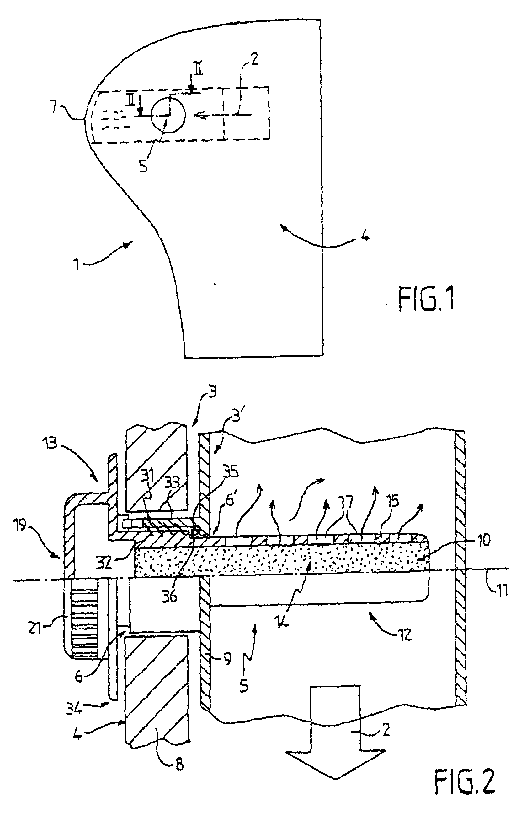
Fig. 1 is a side view of an exemplary embodiment of a dashboard according to the invention;
Fig. 2 is a cross-sectional view along line II-II shown in accordance to Fig. 1;
Fig. 3 is a perspective view illustrating one of the constituent elements of the dashboard
shown in Fig. 2;
Fig. 4 illustrates, along the same section line as used for Fig. 2, an alternative
embodiment of the invention;
Fig. 5 is a cross-sectional view along line V-V as shown in Fig. 4; and
Fig. 6 illustrates a detail, identified by reference VI in preceding Fig. 4.
DETAILED DESCRIPTION OF THE PREFERRED EMBODIMENTS
[0012] As illustrated in Figs. 1, 2 and 4, dashboard 1 allows circulation of at least one
stream of air, along a given path 2. The dashboard defines at least one thickness
of material 3, 3'. The thickness of the material 3.3' define a face 4 of dashboard
1 (as shown in Fig. 1). The face 4 is also called outer face throughout the application
and is adaptable to be temporarily accessible.
[0013] In this application, the term "temporarily accessible" means that the outer face
4 is visible without having to remove all or part of dashboard 1. For example, the
outer face 4 may be the front, as illustrated in Fig. 1 or the lateral faces of the
instrument panel.
[0014] Dashboard 1, also includes diffusing means 5 for diffusing an active compound, in
particular a perfuming agent, in the stream of air along a given path 2.
[0015] According to the invention, the diffusing means 5 are designed to be capable of being
introduced, wholly or in part, through at least one loading orifice 6, 6'. In addition,
the diffusing means 5 are capable of passing through the thicknesses of material 3,
3'. Preferably, the orifices 6, 6' are orientated transversely to path 2. The diffusing
means 5 is held in place and prevented from displacement by holding the diffusing
means 5 in an area of the thicknesses of material 3, 3'.
[0016] Therefore, in accordance with the teachings of the preferred embodiment, an active
compound can be diffused in a stream of air with diffusing means 5. Further, the installation
of the diffusing means 5 is easier as it is carried out via the outside of the dashboard
1 without removing the dashboard. Further, the diffusing means 5 are reliably held
in place.
[0017] It is further possible to diffuse different active components through the passenger
compartment by providing diffusing means 5 having a different active compound for
each air stream.
[0018] According, one preferred embodiment of the present invention, diffusing means 5 are
capable of being removed in relation to the rest of dashboard 1. Therefore, the diffusing
means 5 can be removed or changed, when the active compound has been used up.
[0019] As shown in Fig. 7, the diffusing means 5 are located, in particular, just upstream
of ventilation orifices 7, provided on the front face 4 of said dashboard 1 and in
the area in which the streams of air emerge.
[0020] The dashboard 1 can further include ventilating, heating and/or air conditioning
system (HVAC). Preferably, the HVAC system located upstream of the diffusing means
5.
[0021] As illustrated in Fig. 1, the dashboard 1 comprises an instrument panel capable of
permitting the circulation of one of the air streams in the direction of each of its
lateral ends. In the vicinity of the lateral ends are located at least some of the
ventilation orifices 7. The instrument panel is then provided with the diffusing means
5 in the area of one of its lateral faces, designed to be located opposite the front
doors of the vehicle. Therefore, the diffusing means 5, while remaining accessible,
is concealed when the doors of the vehicle are closed.
[0022] Referring in particular to Fig. 1, the dashboard 1 includes, in particular, a panel
8 defining the outer face 4 and at least one flow conduit 9 for the air stream. As
shown, the conduit 9 is provided behind the panel 8. The loading orifices 6, 6' comprises
a first port 6, provided in the panel 8, and a second port 6', provided in conduit
9. The first port 6 and the second form the loading orifices 6, 6'. The first port
6 and the second port 6' are placed in axial prolongation of one another.
[0023] The diffusing means 5 comprises a cartridge 10 extending in at least one direction
11, or so-called axial direction. The cartridge 10 is capable of being positioned,
over a portion of its diffusing length 12, or so as to extend to meet the air stream.
Preferably, the air stream passes through the diffusing length 12 and over a fixing
portion 13, at least partially in the loading orifice 6, 6'. When the cartridge 10
is in place, the axial direction 11 and the axis of the loading orifice 6, 6', may
possibly coincide.
[0024] As illustrated in Figs. 2 to 4, the cartridge 10 comprises in the diffusing length
12, a support means 14 for the active compound. Preferably, the active compound is
designed to be volatile, and can penetrate through the permeable enclosure 15 covering
the support means 14.
[0025] The permeable enclosure 15 is formed of a reservoir made of a porous material such
as ceramic, foam, paper or the like. Further, the permeable enclosure 15 is capable
of containing or absorbing by capillary effect several millimetres of liquid or other
active substance.
[0026] Referring in particular to Fig. 4, the dashboard 1 can further include means 16 for
causing the permeability of the enclosure 15 to vary. Preferably, the permeable means
16 has a passage surface 17 for the passage of the vapours of the active compound.
The means 16 for causing permeability of the enclosure 15 to vary comprises, a closing
surface 18, mobile between the support means 14 and the enclosure 15. The aperture
of the passage surface 17 and, the movements of the closing surface 18 are controllable
from the end of the cartridge located in the area of the fixing portion 13, at the
outer end 19. Therefore, permeability of the enclosure 15 can be adjusted without
removing either the dashboard 1 or the cartridge 10.
[0027] For this purpose, the enclosure 15 and the closing surface 18 comprise two associated
enclosures, co-operating with one another in translation and/or rotation.
[0028] With regard to translation co-operation, the enclosure 15 and the closing surface
18 have, for example, the same polygonal profile, in particular a square one, and
the closing surface 18 is capable of sliding through the enclosure 15 along their
common longitudinal axis.
[0029] With regard to rotation co-operation, the enclosure 15 and the closing surface 18
comprise two coaxial cylinders. The closing surface 18 is preferably mobile about
its longitudinal axis and has an axial prolongation 20 along the fixing portion 13.
The axial prolongation 20 defines the outer end 19 of cartridge 10. The axial prolongation
20 comprises an adjusting thumb wheel 21 that enables the closing surface 18 to be
rotated.
[0030] As illustrated in Fig. 5, the cartridge 10 may be provided with indexing means 22.
The indexing means 22 helps locate the relative position of the closing surface 18
and the enclosure 15. The indexing means 22 preferably comprises a mobile portion,
provided in the area of the thumb wheel 21, and a fixed portion of the dashboard 1.
[0031] Preferably, the thumb wheel 21 has an annular body 23 provided with internal teeth
24 and stops 25. The teeth 24 co-operate with an index pin 26, mounted at a fixed
point on dashboard 1, for example, in the area of an index ring 27. The index ring
27 is also equipped with stops 28.
[0032] The cooperation between the internal teeth 24 and a pin 26, alters the permeability
of the enclosure 15. The function of the stops 25, 28 of thumb wheel 21 and of index
ring 27 will be explained in greater detail hereinafter.
[0033] The closing surface 18 defines a housing 37 for the support means 14. It is further
designed to be mobile in relation to the enclosure 15 in translation along their common
longitudinal axis. Therefore, the support means 14 can be changed without changing
the entire cartridge 10.
[0034] The indexing means 22 are thus designed to be capable of blocking translation movement
of the closing surface 15, through the snapping the thumb wheel 21 over their fixed
part in fully screwed condition.
[0035] As illustrated in Fig. 6, body 23 of the thumb wheel 21 has, for this purpose a return
member 29. The return member 29 is capable of snapping onto the indexing ring 27 with
the help of inclined planes 30, 30' provided facing one another on the return member
29 and the indexing ring 27.
[0036] With further reference to Figs. 2 and 4, it will be noted that the cartridge 10 includes,
in its fixing portion 13, means 31 for holding the cartridge 10 in place. The means
31 promotes the axial prolongation 32 of the enclosure 15, the axial prolongation
is capable of co-operating with the thicknesses of material 3, 3' to enable the cartridge
10 to be immobilised in the loading orifices 6, 6'.
[0037] The means 31 may be a threaded portion provided on the outer face of the enclosure
15. Alternatively, it may be a tapped portion provided opposite on a section 33 integral
with the conduit 9 around the second port 6'.
[0038] The axial prolongation 32 of enclosure 15 can be provided, in the area of the outer
end 19 of cartridge 10, with a protective ring 34 designed to locally conceal outer
face 4 of dashboard 1. The outer face 4 is thus protected from possible soiling caused
by the introduction of the active compound.
[0039] The axial prolongation 32 of enclosure 15 can further have, at its end located at
the outer end 19 side of cartridge 10, the indexing ring 27 (as shown in Fig. 5).
Therefore, by rotating the thumb wheel 21, stops 25 of the thumb wheel 21 and 28 of
the indexing ring 27 can co-operate with one another and enable the cartridge 10 to
be screwed/unscrewed.
[0040] Dashboard 1 can further include means 35 to ensure air-tightness of the loading orifice
6, 6'. The means 35, preferably comprises a joint, co-operating on one hand, with
a shoulder 36 provided in the area of the enclosure 15 and, on the other hand, with
the walls of the thicknesses of material 3, 3' preferably with section 33.
[0041] The foregoing discussion discloses and describes a preferred embodiment of the invention.
One skilled in the art will readily recognize from such discussion, and from the accompanying
drawings and claims, that changes and modifications can be made to the invention without
departing from the invention as defined in the following claims.
1. A motor vehicle dashboard, permitting the circulation of at least one stream of air,
along a given path (2), behind at least one thickness of material (3, 3') defining
an outer face (4) of said dashboard, said dashboard including diffusing means (5)
for diffusing an active compound in said stream, characterized by the fact that said diffusing means (5) are designed to be capable of being introduced,
wholly or in part, through at least one loading orifice (6, 6'), passing through said
thickness of material (3, 3'), from said outer face (4) and emerging in said stream,
said loading orifice (6, 6') being orientated transversely to the path (2) of said
stream, said diffusing means (5) being also capable of being held in the area of said
thickness or thicknesses of material (3, 3').
2. The dashboard according to claim 1, wherein said diffusing means are removable, wholly
or in part, in relation to the rest of said dashboard (1).
3. The dashboard according to claim 1, wherein said diffusing means (5) are located just
upstream of a ventilation orifice (7), wherein said ventilation orifice (7) is provided
on the front face of said dashboard and in an area where said at least one stream
of air emerges.
4. The dashboard according to claim 3, wherein ventilation orifices are provided at each
of its lateral ends and in the area of lateral faces of the dashboard designed to
be located opposite the front doors of the vehicle.
5. The dashboard according to claim 1, further comprising a panel (8) defining said outer
face (4) and at least one flow conduit (9) for said at least one air stream, provided
behind said panel (8), said loading orifice being constituted by a first port (6),
provided in said panel (8), and by a second port (6'), provided in said conduit (9),
in axial prolongation of one another.
6. The dashboard according to claim 1, wherein said diffusing means (5) comprises a cartridge
(10) extending in at least one direction (11), said cartridge having an elongate diffusing
portion (12) which extends across the path of the air stream.
7. The dashboard according to claim 6, in which said cartridge (10) comprises diffusing
portion (12), a support means (14) for said active compound, designed to be volatile,
and a permeable enclosure (15) covering said support means (14).
8. The dashboard according to claim 7, further including means (16) for causing the permeability
of said enclosure (15) to vary.
9. The dashboard according to claim 8, in which said enclosure (15) has a surface (17)
for the passage of the vapours of said active compound, and said means (16) for causing
permeability to vary comprises a closing surface (18), wherein said closing surface
(18') is mobile between said support means (14) and said enclosure (15), so as to
adjust the aperture of said surface (17), wherein the movements of said closing surface
(18) are controlled from the end of the cartridge (10) located in the area of said
fixing portion (13).
10. The dashboard according to claim 9, in which said enclosure (15) and said closing
surface (18) comprises two coaxial cylinders, said closing surface (18) being mobile
in rotation about its longitudinal axis and having an axial prolongation (20) along
said fixing portion (13), said axial prolongation (20) defining an outer end (19)
of said cartridge (10), wherein said closing surface (18) is driven in rotation by
adjusting a thumb wheel (21).
11. The dashboard according to claim 10, wherein said cartridge (10) is provided with
indexing means (22) permitting locating the relative positioning of said closing surface
(18) and said enclosure (15), wherein said indexing means (22) comprise a mobile portion,
provided in the area of said thumb wheel (21), and by a fixed portion (27) of said
dashboard (1).
12. The dashboard according to claim 11, wherein said closing surface (18), is in translation
movement in relation to said enclosure (15) along their common longitudinal axis,
defines a housing (37) to receive said support means (14), said indexing means (22)
being capable of blocking said translation movement of said indexing surface (18)
through the snapping of said thumb wheel (21) over said fixed portion (27).
13. The dashboard according to claim 7, wherein said cartridge (10) includes, in its fixing
portion (13), means (31) for holding in place, an axial prolongation (32) of said
enclosure (15), said axial prolongation (32) being capable of co-operating with said
thicknesses of material (3, 3') to enable said cartridge (10) be immobilised in said
loading orifices (6, 6').
14. The dashboard according to claim 7, further comprising means (35) to ensure air-tightness
of said loading orifices (6, 6') co-operating, on one hand, with a shoulder (36) in
the area of said enclosure (15) and, on the other hand, with the walls of said thicknesses
of material (3, 3').
1. Kraftfahrzeugarmaturenbrett, das die Zirkulation von zumindest einem Luftstrom einen
vorgegebenen Weg (2) entlang hinter zumindest einer Materialdicke (3, 3') gestattet,
die eine Außenseite (4) des Armaturenbretts definiert, wobei das Armaturenbrett Verbreitungsmittel
(5) zum Verbreiten einer Wirkstoffzusammensetzung in dem Strom beinhaltet, dadurch gekennzeichnet, daß die Verbreitungsmittel (5) so gestaltet sind, daß sie durch zumindest eine Ladeöffnung
(6, 6'), die von der Außenseite (4) die Materialdicke (3, 3') durchläuft und in den
Strom austritt, insgesamt oder teilweise, eingeführt werden können, wobei die Ladeöffnung
(6, 6') vorzugsweise transversal zum Weg (2) des Stroms ausgerichtet ist, wobei die
Verbreitungsmittel (5) außerdem im Bereich der Materialdicke oder -dicken (3, 3')
gehalten sein können.
2. Armaturenbrett nach Anspruch 1, wobei die Verbreitungsmittel (5) in Beziehung zum
Rest des Armaturenbretts (1) insgesamt oder teilweise abnehmbar sind.
3. Armaturenbrett nach Anspruch 1, wobei die Verbreitungsmittel (5) einer Lüftungsöffnung
(7) gerade vorgeschaltet angeordnet sind, wobei die Lüftungsöffnung (7) auf der Vorderseite
des Armaturenbretts und in einem Bereich, in dem der zumindest eine Luftstrom austritt,
vorgesehen sind.
4. Armaturenbrett nach Anspruch 3, wobei Lüftungsöffnungen an jedem seiner Seitenenden
und im Bereich von Seitenflächen des Armaturenbretts vorgesehen sind, die dazu bestimmt
sind, den Vordertüren des Fahrzeugs gegenüber angeordnet zu sein.
5. Armaturenbrett nach Anspruch 1, ferner umfassend eine Abdeckung (8), die die Außenseite
(4) und zumindest eine Stromleitung (9) für den zumindest einen Luftstrom definiert,
welche hinter der Abdeckung (8) vorgesehen ist, wobei die Ladeöffnung durch einen
ersten Durchlaß (6), der in der Abdeckung (8) vorgesehen ist, und einen zweiten Durchlaß
(6'), der in der Leitung (9) vorgesehen ist, welche in axialer Verlängerung voneinander
angeordnet sind, gebildet ist.
6. Armaturenbrett nach Anspruch 1, wobei das Verbreitungsmittel (5) eine Patrone oder
Kapsel (10) umfaßt, die sich in zumindest eine Richtung (11) erstreckt, wobei die
Patrone (10) einen langgestreckten Verbreitungsabschnitt (12) aufweist, der sich über
den Weg (2) des Luftstroms erstreckt.
7. Armaturenbrett nach Anspruch 6, wobei die Patrone (10) den Verbreitungsabschnitt (12),
ein Haltemittel (14) für die Wirkstoffzusammensetzung, die dazu bestimmt ist, flüchtig
zu sein, und eine durchlässige Einfassung (15) umfaßt, die das Haltemittel (14) abdeckt.
8. Armaturenbrett nach Anspruch 7, ferner beinhaltend Mittel (16) zum Bewirken, daß sich
die Durchlässigkeit der Einfassung (15) ändert.
9. Armaturenbrett nach Anspruch 8, wobei die Einfassung (15) eine Fläche (17) für den
Durchgang der Dämpfe der Wirkstoffzusammensetzung aufweist und das Mittel (16) zum
Bewirken, daß sich die Durchlässigkeit ändert, eine Schließfläche (18) umfaßt, wobei
die Schließfläche (18) zwischen dem Haltemittel (14) und der Einfassung (15) beweglich
angeordnet ist, um die Öffnung der Fläche (17) anzupassen, wobei die Bewegungen der
Schließfläche (18) von dem Ende der Patrone (10) gesteuert sind, das im Bereich des
Befestigungsabschnitts (13) angeordnet ist.
10. Armaturenbrett nach Anspruch 9, wobei die Einfassung (15) und die Schließfläche (18)
zwei koaxiale Zylinder umfassen, wobei die Schließfläche (18) vorzugsweise um ihre
Längsachse drehbeweglich ist und entlang des Befestigungsabschnitts (13) eine axiale
Verlängerung (20) aufweist, wobei die axiale Verlängerung (20) ein äußeres Ende (19)
der Patrone (10) definiert, wobei die Schließfläche (18) durch Anpassen eines Einstellrads
(21) in der Drehung angetrieben ist.
11. Armaturenbrett nach Anspruch 10, wobei die Patrone (10) mit Schaltmitteln oder Positionierungsmitteln
(22) versehen ist, die es gestatten, die relative Position der Schließfläche (28)
und der Einfassung (15) festzustellen, wobei die Schaltmittel (22) einen beweglichen
Abschnitt, der im Bereich des Einstellrads (21) vorgesehen ist, und einen starren
Abschnitt (27) des Armaturenbretts (1) beinhaltet.
12. Armaturenbrett nach Anspruch 11, wobei sich die Schließfläche (18) in einer Translationsbewegung
in Bezug auf die Einfassung (15) entlang ihrer gemeinsamen Längsachse befindet, ein
Gehäuse (37) zum Aufnehmen der Haltemittel (14) definiert, wobei die Schaltmittel
oder Positionierungsmittel (22) die Translations- oder Übersetzungsbewegung der Schließfläche
(18) durch das Schnappen des Einstellrads (21) über dem starren Abschnitt (27) blockieren
können.
13. Armaturenbrett nach Anspruch 7, wobei die Patrone (10) in ihrem Befestigungsabschnitt
(13) Mittel (31) zum Festhalten, eine axiale Verlängerung (32) der Einfassung (15)
beinhaltet, wobei die axiale Verlängerung (32) imstande ist, mit den Materialdicken
(3, 3') zu kooperieren, um zu ermöglichen, daß die Patrone (10) in den Ladeöffnungen
(6, 6') festgestellt ist.
14. Armaturenbrett nach Anspruch 7, ferner umfassend Mittel (35) zum Gewährleisten der
Luftundurchlässigkeit der Ladeöffnungen (6, 6'), die einerseits mit einem Vorsprung
(36) im Bereich der Einfassung (15) und andererseits mit den Wänden der Materialdicken
(3, 3') kooperieren.
1. Tableau de bord de véhicule à moteur, permettant la circulation d'au moins un flux
d'air, le long d'un trajet donné (2), derrière au moins une épaisseur de matériau
(3, 3') définissant une face extérieure (4) dudit tableau de bord, ledit tableau de
bord comprenant des moyens de diffusion (5) destinés à diffuser un composé actif dans
ledit flux, caractérisé par le fait que lesdits moyens de diffusion (5) sont conçus pour pouvoir être introduits, entièrement
ou en partie, à travers au moins un orifice de chargement (6, 6'), traversant ladite
épaisseur de matériau (3, 3'), depuis ladite face extérieure (4) et apparaissant dans
ledit flux, ledit orifice de chargement (6, 6') étant orienté de façon transversale
au trajet (2) dudit flux, ledit moyen de diffusion (5) pouvant également être maintenu
dans la zone de ladite épaisseur ou desdites épaisseurs de matériau (3, 3').
2. Tableau de bord selon la revendication 1, dans lequel lesdits moyens de diffusion
peuvent être retirés, entièrement ou en partie, par rapport au reste dudit tableau
de bord (1).
3. Tableau de bord selon la revendication 1, dans lequel lesdits moyens de diffusion
(5) sont situés juste en amont d'un orifice de ventilation (7), dans lequel ledit
orifice de ventilation (7) est prévu sur la face avant dudit tableau de bord et dans
une zone où ledit au moins un flux d'air émerge.
4. Tableau de bord selon la revendication 3, dans lequel des orifices de ventilation
sont prévus au niveau de chacune de ces extrémités latérales et dans la zone des faces
latérales du tableau de bord conçues pour être situées de façon opposée aux portes
avant du véhicule.
5. Tableau de bord selon la revendication 1, comprenant en outre un panneau (8) définissant
ladite face extérieure (4) et au moins un conduit d'écoulement (9) destiné audit au
moins un flux d'air, disposé derrière ledit panneau (8), ledit orifice de chargement
étant constitué d'une première ouverture (6) réalisée dans ledit panneau (8), et d'une
seconde ouverture (6'), réalisée dans ledit conduit (9), suivant un prolongement axial
l'une par rapport l'autre.
6. Tableau de bord selon la revendication 1, dans lequel lesdits moyens de diffusion
(5) comprennent une cartouche (10) s'étendant dans au moins une direction (11), ladite
cartouche comportant une partie de diffusion allongée (12) qui s'étend en travers
du trajet du flux d'air.
7. Tableau de bord selon la revendication 6, dans lequel ladite cartouche (10) comprend
une partie de diffusion (12), un moyen de support (14) destiné audit composé actif,
conçu pour être volatil, et une enceinte perméable (15) recouvrant ledit moyen de
support (14).
8. Tableau de bord selon la revendication 7, comprenant en outre un moyen (16) destiné
à amener la perméabilité de ladite enceinte (15) à varier.
9. Tableau de bord selon la revendication 8, dans lequel ladite enceinte (15) comporte
une surface (17) pour le passage des vapeurs dudit composé actif, et ledit moyen (16)
destiné à amener la perméabilité à varier comprend une surface de fermeture (18),
où ladite surface de fermeture (18') est mobile entre ledit moyen de support (14)
et ladite enceinte (15), de façon à régler l'ouverture de ladite surface (17), où
les mouvements de ladite surface de fermeture (18) sont commandés depuis l'extrémité
de la cartouche (10) située dans la zone de ladite partie de fixation (13).
10. Tableau de bord selon la revendication 9, dans lequel ladite enceinte (15) et ladite
surface de fermeture (18) comprennent deux cylindres coaxiaux, ladite surface de fermeture
(18) étant mobile en rotation autour de son axe longitudinal et présentant un prolongement
axial (20) le long de ladite partie de fixation (13), ledit prolongement axial (20)
définissant une extrémité extérieure (19) de ladite cartouche (10), où ladite surface
de fermeture (18) est entraînée en rotation en réglant une molette (21).
11. Tableau de bord selon la revendication 10, dans lequel ladite cartouche (10) est munie
d'un moyen de positionnement (22) permettant de situer le positionnement relatif de
ladite surface de fermeture (18) et de ladite enceinte (15), dans lequel ledit moyen
de positionnement (22) comprend une partie mobile, prévue dans la zone de ladite molette
(21), et une partie fixe (27) du tableau de bord (1).
12. Tableau de bord selon la revendication 11, dans lequel ladite surface de fermeture
(18) effectue un mouvement de translation par rapport à ladite enceinte (15) le long
de leur axe longitudinal commun et défini un logement (37) destiné à recevoir ledit
moyen de support (14), ledit moyen de positionnement (22) permettant de bloquer ledit
mouvement de translation de ladite surface de positionnement (18) par l'intermédiaire
de l'emboîtement de ladite molette (21) sur ladite partie fixe (27).
13. Tableau de bord selon la revendication 7, dans lequel ladite cartouche (10) comprend,
dans sa partie de fixation (13), un moyen (31) destiné à maintenir en place un prolongement
axial (32) de ladite enceinte (15), ledit prolongement axial (32) pouvant coopérer
avec lesdites épaisseurs de matériau (3, 3') pour permettre que ladite cartouche (10)
soit immobilisée dans lesdits orifices de chargement (6, 6').
14. Tableau de bord selon la revendication 7, comprenant en outre un moyen (35) pour assurer
l'étanchéité à l'air desdits orifices de chargement (6, 6') coopérant, d'une part,
avec un épaulement (36) dans la zone de ladite enceinte (15) et d'autre part, avec
les parois desdites épaisseurs de matériau (3, 3').