|
(11) | EP 1 121 484 B1 |

| (12) | EUROPEAN PATENT SPECIFICATION |
|
|
| (54) |
A LONG NIP PRESS LANGSPALTPRESSE PRESSE A LONGUE ZONE DE CONTACT |
|
|
|||||||||||||||||||||||||||||||
| Note: Within nine months from the publication of the mention of the grant of the European patent, any person may give notice to the European Patent Office of opposition to the European patent granted. Notice of opposition shall be filed in a written reasoned statement. It shall not be deemed to have been filed until the opposition fee has been paid. (Art. 99(1) European Patent Convention). |
[0001] The invention relates to the field of fibre web dewatering. In particular, the invention relates to a long pressing zone press for the treatment of a fibre web.
[0002] The dewatering of a fibre web is usually carried out by means of roller presses, by leading the web via a press zone formed by two rolls, i.e. through a press nip. The web runs through the nip between press felts and the felts carry away the water squeezed out of the web.
[0003] In a nip formed by two rolls, the greatest pressing force is reached as a narrow peak in the middle of the nip. This is disadvantageous both to the dewatering process and to the service life of the felts, because at high velocities, the pressing is of a very short duration and great stress is put on the felts. Therefore, different kinds of so-called long nip presses have been constructed wherein one roll can be substituted by a concave counterpart, by a press shoe. On the shoe side, the rotary motion of the roll is usually matched by a watertight, endless loop of fabric, a press belt that glides on the surface of the lubricated counterpart following its shape. The press belt is supported by separate rolls, or alternatively, the shoe support is given a shape that enables a short belt to glide around it, lubrication being provided on the inside of the endless loop formed by the belt. By the use of shoe presses, press nips whose effective length can be approximately 250 - 310 mm, depending on the size of the roll, are achieved. In addition to roll/shoe combinations, the patent documents mentioned later disclose presses composed of two opposite shoes.
[0004] Patent application CH-A-5152 discloses a press shoe. On its surface, under the press belt, cavities are provided that serve as hydrostatic pressure chambers when hydraulic fluid is led into them through channels in the shoe. In addition to pressure, a stepped heat treatment for the web is achieved by individually regulating the temperature of the hydraulic fluid in the separate chambers. Patent application FI-A-896163 also discloses a press shoe having a plurality of pockets on its sliding surface for feeding an individually pressurised lubricant, the pressure profile being adjustable in the nip zone for desired pressing and web speed conditions. Swedish patent application SE-A-9103823 (& US-A-5 262 011) discloses a press shoe provided with a pressure pocket, wherein the depth profile of the pressure pocket results in a combination of hydrostatic and hydrodynamic effects for obtaining a desired pressing force profile.
[0005] The object of the present invention is to provide a straightforward long nip press structure usable for the dewatering of a fibre web. The object is achieved through the construction according to claim 1, comprising a roll and a concave counterpart. A hydraulic pressure chamber is provided on the surface of the counterpart, under a gliding press belt. No press shoe in the usual sense of the word is employed, as a result of which no hydraulic cylinder control systems, which are typical of shoe presses, for adjusting the tilt and the radial position of a shoe are needed.
[0006] Because of the simple structure, the sealing of the edges of the hydraulic pressure chamber of the counterpart remains a problem. According to the present invention, the press belt is tightened by pressurising the space on the inside of the press belt in the counterpart. This pressure will hereinafter be referred to as belt pressure. The belt pressure, which is applied to the inner surface of the belt from the direction of the counterpart, is proportional to the pressure of the pressure chamber. When the ratio of the radius of curvature of the pressure chamber edge to the radius of the general path of the belt corresponds to the ratio of the belt pressure to the pressure of the pressure chamber, no oil leakage occurs from the pressure chamber. When the ratio of said pressures is maintained at at a value appropriately lower than that of the ratio of said radii to each other, a sufficient amount of oil escapes from the pressure chamber to lubricate the sliding surfaces between the belt and the counterpart.
[0007] The structure of the press is thus considerably simple but provides sufficient means to regulate the compression pressure in the nip zone and, consequently, to influence the properties of the pulp web leaving the press. The edges of the pressure chamber are located outside the nip zone. As the pressure of the chamber forces the belt to follow the surface of the roll, the nip length can be adjusted by adjusting the distance between the roll and the counterpart.
[0008] The belt pressure can be generated by means of a fluid, preferably oil; or gas, preferably air. Preferably, the belt is made from fiber reinforced rubber.
[0009] The invention will now be described in closer detail with reference to the accompanying drawings wherein
figure 1 is a sectional view of a press according to the invention, taken in the direction of web motion, and
figure 2 is a corresponding sectional view of an another embodiment of a press according to the invention.
[0010] Referring to figure 1, a fiber web 1 enters the press from the left, supported by felts or wires 2 and 3. A press nip is formed between a roll 4 and a counterpart 5. The counterpart comprises a beam body 6, on which a cavity 7 has been formed, and a cylindrical shell 8. When the press is in use, an endless press belt 9 glides on shell 8. The cavity 7 forms a pressure chamber together with the press belt 9. The force exerted on the web in the nip can be regulated by regulating the pressure of the oil fed to the pressure chamber.
[0011] A belt pressure p2 generated by oil fed by means of a pipeline 10 prevails between the press belt 9 and the shell 8. The friction between the press belt and the counterpart is eliminated by allowing oil to leak in a controlled manner over the thresholds 11, 12, the oil carried on the press belt lubricating the sliding surfaces between the belt and the counterpart. A certain oil level can be maintained in the lower section of the counterpart, and the lower part of the shell 8 can be provided with openings below the oil level, if this is necessary for the lubrication of the press belt. The oil in the lower section of the counterpart can be returned to the circulatory system by means of collecting pipes 13.
[0012] The force influencing the press belt outside the thresholds 11, 12 is determined by the relation between the counterpart radius R and the edge radius r. When the pressure in the pressure chamber is denoted by p1 and the belt pressure is denoted by p2, the pressures acting on different sides of the edges are in balance when
[0013] In this situation there is no oil leakage, and, consequently, an efficient lubrication requires that
[0014] Figure 2 shows an alternative structure for the counterpart, wherein the belt pressure is generated by means of compressed air. The shell of the counterpart is constituted by a perforated cylinder 14, and the belt pressure p2 prevails in all parts of the counterpart outside the pressure chamber. The cylinder 14 does not extend to the upper edges of the beam body, but the oil leaking out of the pressure chamber, and further across the edges 15, 16, flows along surfaces 17, 18 into oil collecting chutes 19, 20 from which the oil can be returned to the circulatory system. The counterpart comprises oil-collecting pipes 21 in its lower part as well.
1. A method of arranging a sealing and lubricating system between a counterpart (5) and
a press belt (9) in a press comprising a roll (4), the counterpart for it provided
with an endless press belt, and an oil-filled pressure chamber arranged on the surface
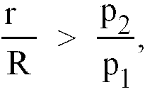
of the counterpart, under the press belt, characterised in that the pressures acting under the press belt (9) in the counterpart (5) satisfy the
following condition
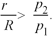
wherein r = the radius of curvature of the edge of the pressure chamber, R = the radius of the cylindrical surface of the counterpart, p1 = the pressure acting in the pressure chamber, and p2 = the pressure acting under the press belt outside the pressure chamber.
wherein r = the radius of curvature of the edge of the pressure chamber, R = the radius of the cylindrical surface of the counterpart, p1 = the pressure acting in the pressure chamber, and p2 = the pressure acting under the press belt outside the pressure chamber.
2. A method as defined in claim 1, characterised in that the amount of oil used for the lubrication between the press belt (9) and the counterpart
(5) is controlled by adjusting the pressure prevailing under the press belt outside
the pressure chamber.
3. A method as defined in claim 1 or 2, characterised in that the pressure prevailing under the press belt (9) outside the pressure chamber is
generated by means of oil.
4. A method as defined in claim 1 or 2, in that the pressure prevailing under the press
belt (9) outside the pressure chamber is generated by means of gas.
5. A method as defined in any claim 1 to 4, characterised in that the length of the nip of the press is adjusted by adjusting the distance between
the roll (4) and the counterpart (5).
6. A press comprising a roll (4), a counterpart (5) for it provided with an endless press
belt (9), and an oil-filled pressure chamber arranged on the surface of the counterpart,
under the press belt, characterised in that it also comprises a means of generating a pressure between the press belt (9) and
the counterpart (5) outside the pressure chamber.
7. A press as defined in claim 6, characterised in that the pressure is generated by means of gas.
8. A press as defined in claim 6, characterised in that the pressure is generated by means of oil.
1. Verfahren zum Anordnen eines Dichtungs- und Schmiersystems zwischen einem Gegenstück
(5) und einem Preßband (9) in einer Presse, die eine Walze (4) aufweist, wobei das
Gegenstück für sie mit einem endlosen Preßband und einer auf der Oberfläche des Gegenstücks
unter dem Preßband angeordneten ölgefüllten Druckkammer versehen ist, dadurch gekennzeichnet, daß die unter dem Preßband (9) in dem Gegenstück (5) wirkenden Drücke die folgende Bedingung
erfüllen
wobei r = Krümmungsradius des Rands der Druckkammer, R = Radius der zylindrischen Oberfläche des Gegenstücks, p1 = der in der Druckkammer wirkende Druck und p2 = der unter dem Preßband außerhalb der Druckkammer wirkende Druck.
wobei r = Krümmungsradius des Rands der Druckkammer, R = Radius der zylindrischen Oberfläche des Gegenstücks, p1 = der in der Druckkammer wirkende Druck und p2 = der unter dem Preßband außerhalb der Druckkammer wirkende Druck.
2. Verfahren nach Anspruch 1, dadurch gekennzeichnet, daß die zum Schmieren zwischen dem Preßband (9) und dem Gegenstück (5) verwendete Ölmenge
gesteuert wird, indem der unter dem Preßband außerhalb der Druckkammer vorherrschende
Druck eingestellt wird.
3. Verfahren nach Anspruch 1 oder 2, dadurch gekennzeichnet, daß der unter dem Preßband (9) außerhalb der Druckkammer vorherrschende Druck mittels
Öl erzeugt wird.
4. Verfahren nach Anspruch 1 oder 2, dadurch gekennzeichnet, daß der unter dem Preßband (9) außerhalb der Druckkammer vorherrschende Druck mittels
Gas erzeugt wird.
5. Verfahren nach einem der Ansprüche 1 bis 4, dadurch gekennzeichnet, daß die Länge des Spalts der Presse eingestellt wird, indem der Abstand zwischen der
Walze (4) und dem Gegenstück (5) eingestellt wird.
6. Presse, die aufweist: eine Walze (4), ein Gegenstück (5) dazu, das mit einem endlosen
Preßband (9) und einer auf der Oberfläche des Gegenstücks unter dem Preßband angeordneten
ölgefüllten Druckkammer versehen ist, dadurch gekennzeichnet, daß sie auch eine Einrichtung zum Erzeugen eines Drucks zwischen dem Preßband (9) und
dem Gegenstück (5) außerhalb der Druckkammer aufweist.
7. Presse nach Anspruch 6, dadurch gekennzeichnet, daß der Druck mittels Gas erzeugt wird.
8. Presse nach Anspruch 6, dadurch gekennzeichnet, daß der Druck mittels Öl erzeugt wird.
1. Procédé pour agencer un système de mise à l'échelle et de lubrification entre une
contre empreinte (5) et une courroie pressante (9) dans une presse comprenant un rouleau
(4), la contre-empreinte pour celle-ci étant pourvue d'une courroie pressante sans
fin, et une chambre de pression remplie d'huile agencée sur la surface de la contre-empreinte,
sous la courroie pressante, caractérisé en ce que les pressions agissant sous la courroie pressante (9) dans la contre-empreinte (5)
satisfont la condition suivante :

où r est le rayon de courbure du bord de la chambre de pression, R est le rayon de la surface cylindrique de la contre-empreinte, P1 est la pression agissant dans la chambre de pression, et P2 est la pression agissant sous la courroie pressante à l'extérieur de la chambre de pression.
où r est le rayon de courbure du bord de la chambre de pression, R est le rayon de la surface cylindrique de la contre-empreinte, P1 est la pression agissant dans la chambre de pression, et P2 est la pression agissant sous la courroie pressante à l'extérieur de la chambre de pression.
2. Procédé selon la revendication 1, caractérisé en ce que la quantité d'huile utilisée pour la lubrification entre la courroie pressante (9)
et la contre-empreinte (5) est contrôlée en réglant la pression prévalant sous la
courroie pressante à l'extérieur de la chambre de pression.
3. Procédé selon la revendication 1 ou 2,
caractérisé en ce que la pression prévalant sous la courroie pressante (9) à l'extérieur de la chambre de pression est générée au moyen d'huile.
caractérisé en ce que la pression prévalant sous la courroie pressante (9) à l'extérieur de la chambre de pression est générée au moyen d'huile.
4. Procédé selon la revendication 1 ou 2,
caractérisé en ce que la pression prévalant sous la courroie pressante (9) à l'extérieur de la chambre de pression est générée au moyen de gaz.
caractérisé en ce que la pression prévalant sous la courroie pressante (9) à l'extérieur de la chambre de pression est générée au moyen de gaz.
5. Procédé selon la revendication 1 à 4,
caractérisé en ce que la longueur de la bande de la presse est ajustée en réglant la distance entre le rouleau (4) et la contre-empreinte (5).
caractérisé en ce que la longueur de la bande de la presse est ajustée en réglant la distance entre le rouleau (4) et la contre-empreinte (5).
6. Presse comprenant un rouleau (4), une contre-empreinte (5) pour celle-ci pourvue d'une
courroie pressante sans fin (9), et une chambre de pression remplie d'huile agencée
sur la surface de la contre-empreinte, sous la courroie pressante, caractérisée en ce qu'elle comprend également des moyens de génération de pression entre la courroie pressante
(9) et la contre-empreinte (5) à l'extérieur de la chambre de pression.
7. Presse selon la revendication 6, caractérisée en ce que la pression est générée au moyen de gaz.
8. Presse selon la revendication 6, caractérisée en ce que la pression est générée au moyen d'huile.