| (19) |
 |
|
(11) |
EP 1 218 581 B1 |
| (12) |
EUROPEAN PATENT SPECIFICATION |
| (45) |
Mention of the grant of the patent: |
|
02.06.2004 Bulletin 2004/23 |
| (22) |
Date of filing: 08.09.2000 |
|
| (51) |
International Patent Classification (IPC)7: D04B 7/30 |
| (86) |
International application number: |
|
PCT/IT2000/000356 |
| (87) |
International publication number: |
|
WO 2001/020067 (22.03.2001 Gazette 2001/12) |
|
| (54) |
A PROCESS FOR KNITTING A WEFT-KNITTED FABRIC SO THAT CUT PILE IS FORMED ON THE BACKSIDE
STITCHES, A KNITTING MACHINE OPERATING ACCORDING TO THE PROCESS AND A KNITTED FABRIC
OBTAINABLE WITH SUCH PROCESS AND MACHINE
VERFAHREN ZUR HERSTELLUNG EINER SCHUSS-STRICKWARE MIT AM RÜCKSEITEMASCHEN GEFORMTEN
SCHNITTPOL, NACH DIESEM VERFAHREN ARBEITENDE STRICKMASCHINE UND DAMIT ERHALTENE STRICKWARE
PROCEDE DE TRICOTAGE A MAILLES CUEILLIES AVEC FORMATION DE POIL COUPE SUR LES MAILLES
ENVERS, MACHINE A TRICOTER CORRESPONDANTE ET TISSU MAILLE OBTENU PAR CE PROCEDE AVEC
LADITE MACHINE
|
| (84) |
Designated Contracting States: |
|
AT BE CH CY DE DK ES FI FR GB GR IE IT LI LU MC NL PT SE |
|
Designated Extension States: |
|
RO |
| (30) |
Priority: |
14.09.1999 IT FI990190
|
| (43) |
Date of publication of application: |
|
03.07.2002 Bulletin 2002/27 |
| (73) |
Proprietors: |
|
- Pinzauti, Adriano
51037 Montale (IT)
- Pinzauti, Lucia
51037 Montale (IT)
|
|
| (72) |
Inventor: |
|
- PINZAUTI, Piero
I-51037 Montale (IT)
|
| (74) |
Representative: Bardini, Marco Luigi et al |
|
c/o Società Italiana Brevetti
Corso dei Tintori, 25
50122 Firenze
50122 Firenze (IT) |
| (56) |
References cited: :
US-A- 3 845 641
|
US-A- 4 900 605
|
|
| |
|
|
|
|
| |
|
| Note: Within nine months from the publication of the mention of the grant of the European
patent, any person may give notice to the European Patent Office of opposition to
the European patent
granted. Notice of opposition shall be filed in a written reasoned statement. It shall
not be deemed to
have been filed until the opposition fee has been paid. (Art. 99(1) European Patent
Convention).
|
Field of the Invention
[0001] The present invention relates to the field of knitted fabrics, and namely it concerns
a new knitting process for obtaining a so-called "pile" fabric. The invention also
relates to a knitting machine aimed at operating according to the process, and a knitted
fabric obtainable with such process and machine.
Background art
[0002] Presently, the textile industry offers a wide range of so-called "pile" fabrics,
i. e. fabrics providing on one side a distribution of tufts or hairs, formed by way
of a effect (or pile) yarn. The processes for manufacturing such fabrics, and consequently
the machines aimed at carrying out them, are likewise various. Considering in particular
the cut pile knitted fabrics obtained by means of flat or circular knitting machines
- disregarding ecological furs and
peluche fabrics - according to the prior art, loops are formed, like in the terry fabrics,
and cut during the finishing steps, through the so-called "shearing" operation.
[0003] With this process it is not possible to obtain pile fancy patterns, because the terry
fabric knitting machines do not allow to freely arrange the pile loops, as a function
of the pattern one wishes to obtain on a side of the fabric.
[0004] Besides, the shearing operation involves up to 30% yarn wastes (pile loops are cut
about half their length), thus causing a remarkable increase in the production costs,
which are in any case burdened by the additional shearing productive step.
Summary of the Invention
[0005] The main object of the present invention is to allow the manufacturing of a weft-knitted
fabric so that cut pile is formed in the course of the knitting productive step.
[0006] While accomplishing the above mentioned general object, a particular object of the
present invention is to permit a free arrangement of the cut pile among the normal
stitches of the fabric, in order to obtain pile fancy designs and/or patterns.
[0007] Said objects are attained with the weft-knitting process having the essential features
defined in appended claim 1.
[0008] An improved knitting machine operating according to the process is essentially as
defined by appended claim 10.
[0009] A knitted fabric obtainable with such process and machine has the features essentially
defined by appended claim 20.
Brief description of the drawings
[0010] For a fuller appreciation of the features and advantages afforded by the process
for knitting a weft-knitted fabric so that cut pile is formed on the backside stitches,
the knitting machine operating according to the process and the knitted fabric obtainable
with such process and machine according to the present invention, a preferred embodiment
thereof will now be described by way purely of example and implying no limitation,
with reference to the accompanying drawings, in which:
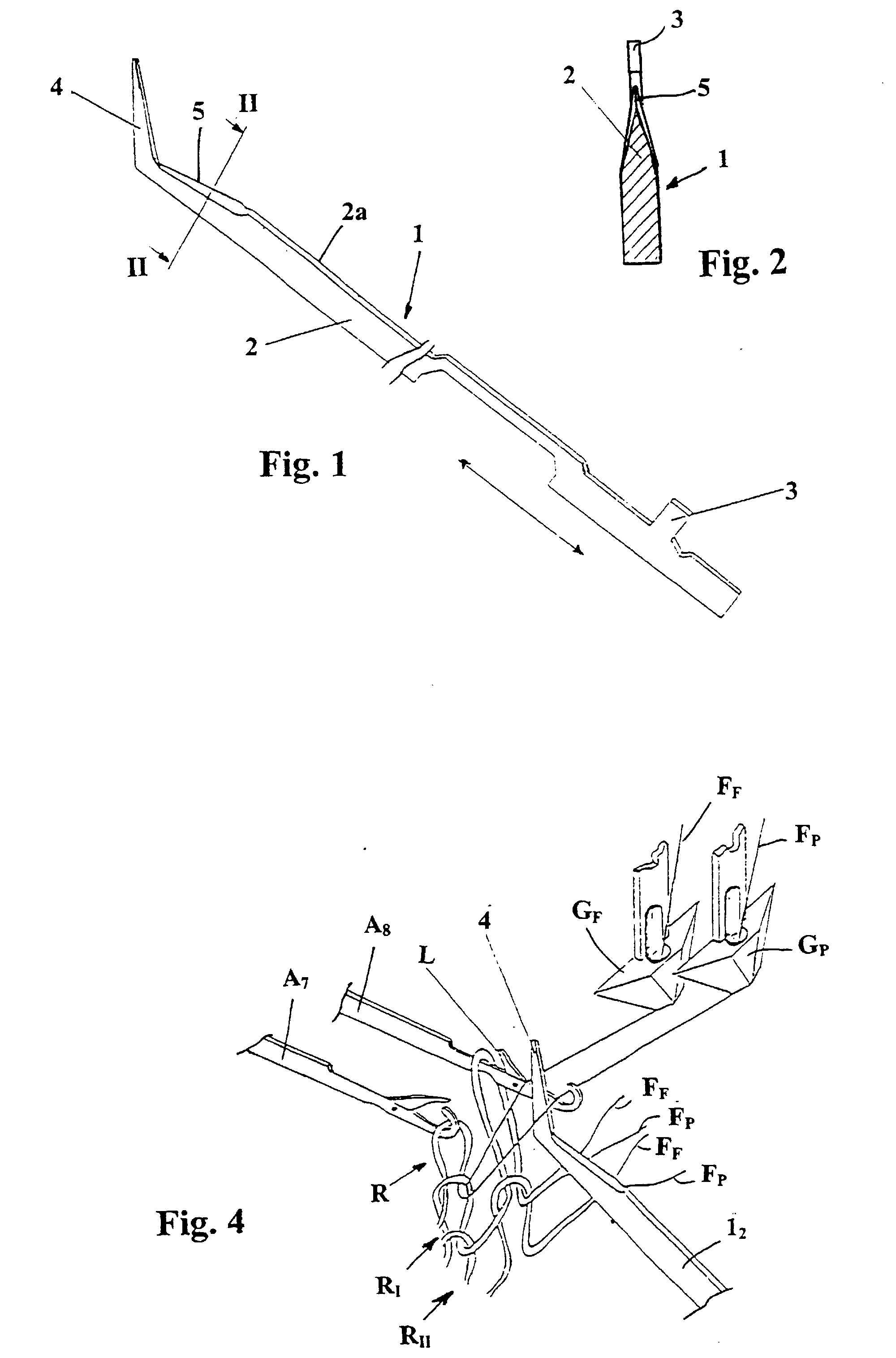
- figure 1 shows a perspective view of a slidable member for use in the process according
to the invention;
- figure 2 shows a cross section view taken along line II-II of figure 1;
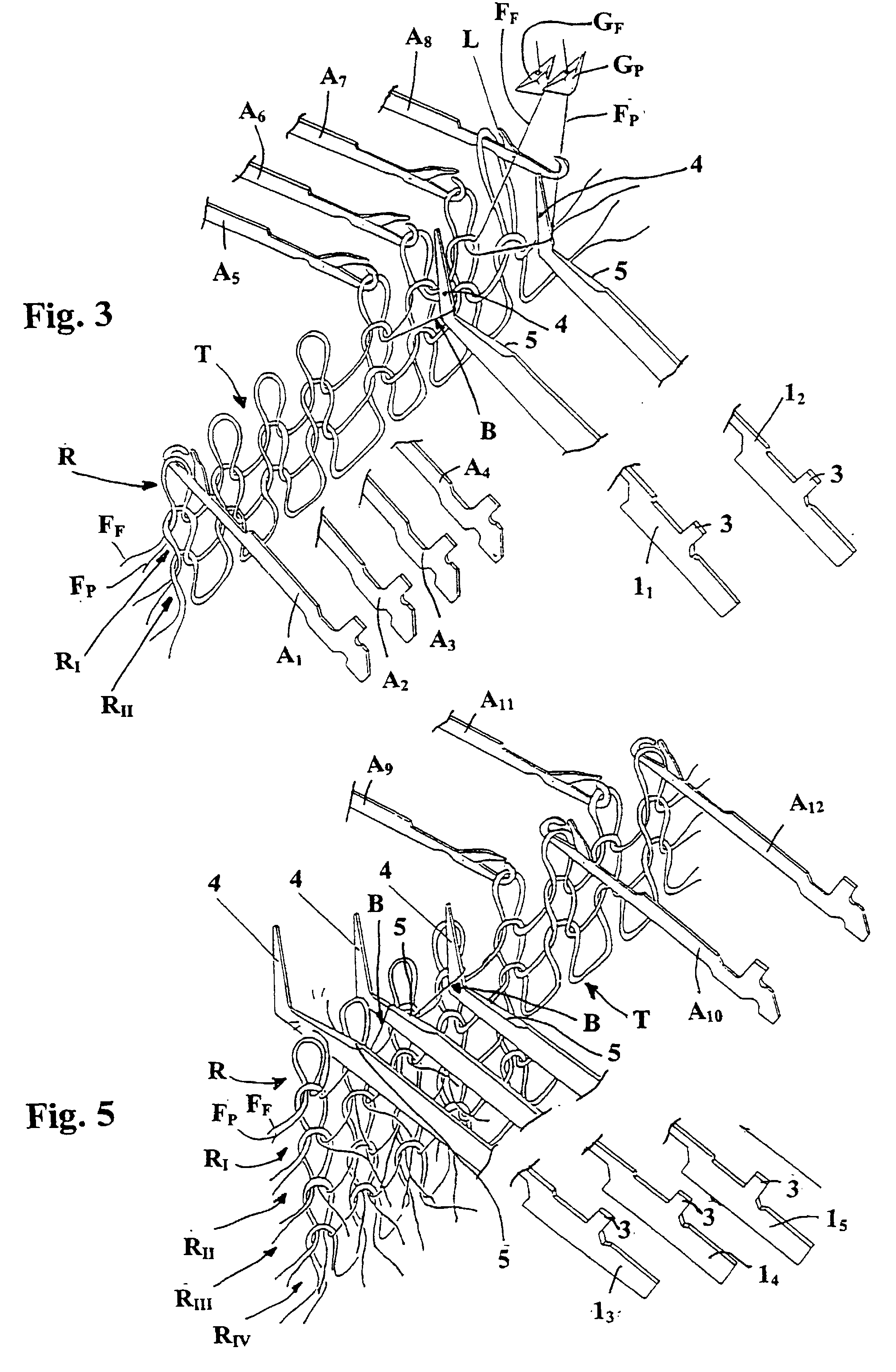
- figures 3, 4 and 5 show partial and schematic perspective views of the opposite needlebeds
of a flat knitting machine operating according to the invention, in respective successive
steps of the pile-forming knitting process.
Description of the preferred embodiment
[0011] With reference to figures 1 and 2, according to a preferred embodiment of the invention,
a slidable member 1 is used, having an elongated shape comprising a shank 2 which
is provided with an end butt 3 for allowing a reciprocating operation, according to
the system commonly used for operating knitting needles. Butt 3 extends in a orthogonal
direction from an edge 2a of shank 2, such edge being that which, in use, is placed
upwards, as will be explained hereinafter.
[0012] The other end of slidable member 1, i. e. the working end thereof - also in this
case, as will be made clearer hereinafter - has a pointed foot 4, which extends from
upper edge 2a of shank 2, accomplishing a substantially L-shaped arrangement. A cutting
rim portion 5 is formed by upper edge 2a of shank 2, close to foot 4. In the depicted
example cutting rim 5 slightly slopes towards foot 4.
[0013] With reference now to figure 3, in a flat knitting machine, neither shown nor described
as a whole since for all that is not explicitly mentioned its features are according
to the prior art, two opposite knitting needlebeds cooperate in order to form a knitted
fabric T. In greater detail, consecutive courses of stitches R, R
I, R
II of fabric T are visible, the latest of said courses - that is to say course R which
is being formed in the represented step - has the relevant stitch loops engaged by
the knitting needles.
[0014] Namely, needles A
1, A
2, A
3 and A
4 - needles A
2 to A
4 being illustrated only partially, for the sake of clarity - are loaded with the loops
of newly formed rightside stitches, while needles A
5, A
6 and A
7 of the opposite needlebed are loaded with backside stitch loops. A following needle
A
8 of this same needlebed is forming the pertinent stitch of course R, as described
in detail later on. Besides, it has to be noticed that the weft of fabric T is formed
by a base yarn thread F
F and a effect or pile yarn thread F
P, mutually coupled. Running along threads F
F and F
P, a rightside stitch portion formed by needles from A
1 to A
4 is followed by a backside stitch portion formed by needles from A
5 to A
7. The threads are fed by feeders G
F, for base thread F
F, and G
P, for pile thread F
P.
[0015] According to the preferred embodiment of the invention, slidable members 1 operatively
replace respective needles of the needlebed which is opposite to that creating the
base of the pertinent stitches, in order to form cut pile in correspondence thereof.
For instance, figure 3 shows two slidable members 1
1 and 1
2, slidably housed in the grooves which, in a conventional machine, respectively between
needles A
5 and A
6 and between needles A
7 and A
8 of a needlebed, support needles of the needlebed opposite thereto. The cut pile is
formed according to the following working steps, described as far as needle As is
concerned and referring also to figure 4.
[0016] Needle A
8, loaded with a stitch of course R
I (previous to course R which is being formed), is operated by the machine cam system
and moves forward, so that the old stitch opens the corresponding lever, indicated
at L, and locates under the same. Then, needle A
8 starts moving backward and feeders G
F and G
P bring the respective threads F
F and F
P in front of the needle hook, allowing the latter to engage with them.
[0017] In the meantime, sliding member 1
2 - placed between needle A
8 and the previous one A
7 - has moved forward, locating the tip of its foot 4 in correspondence to the theoretical
intersection axis between the planes of the two needlebeds. In this condition, as
the feeders G
F e G
P pass, foot 4, of which the tip is slightly higher than the needle hooks, inserts
between the base thread F
F and the pile thread F
P, so as to keep them separate. Figures 3 and 4 actually represent such phase, in two
steps immediately following one another, and it is clearly noticeable how foot 4 retains
pile thread F
P as this is hooked by needle A
8.
[0018] When needle A
8 stops its backward motion, the old stitch of course R
I has been unloaded, after closing lever L, and a new stitch of course R has been formed.
However, foot 4 of sliding member 1
2 has formed a bridle B between the beginning of the upper loop of said new stitch
and the end of the previous stitch of the same course R, i. e. the stitch that is
engaged by needle A
7. This condition is shown more clearly in figure 3, in respect of needles A
5 and A
6 and the corresponding sliding member 1
1. The latter, by retaining pile thread F
P, has thereby formed a bridle B, while base thread F
F has conventionally formed a normal lower loop.
[0019] The release of fabric T from the engagement with feet 4 of sliding members 1, necessary
in order to allow the drop of the fabric itself operated by the takedowri system of
the machine, is accomplished as bridle B is cut by cutting rim portion 5 of the sliding
member, thus forming the cut pile. Such stage is shown in figure 5, in which three
adjacent sliding members 1
5, 1
4 and 1
3 are represented in three successive working steps. Starting from the position retaining
bridle B formed by thread F
P (sliding member 1
5), the member forward movement according to the arrow causes bridle B to drop over
cutting portion 5 (member 1
4) and then the cutting off of thread F
P, consequently forming the cut pile (member 1
3). The cutting off of thread F
P is made easier by the fact that bridle B is stretched over cutting portion 5, such
condition being assisted by the slight slope thereof towards foot 4.
[0020] The result which is accomplished can be clearly seen in the same figure 5, wherein
cut pile formations are represented also in previously knitted courses R
I, R
II, R
III and R
IV, in correspondence to the stitches involved by the operation of sliding members 1.
In this respect, it has to be noticed that the length of the pile formed can be easily
adjusted by suitably controlling the operation of sliding member 1. In fact, a backward
displacement of the latter during the stage in which bridle B is engaged by foot 4
- that is to say the stage shown in figures 3 and 4 - pulls more thread F
P from the corresponding feeder G
P, thus causing the bridle B to become longer. In other words, the length of the pile
directly responds to the extent of said backward displacement of sliding member 1.
[0021] On the other hand, as said backward displacement of sliding member 1 increases, and
the bridle B gets longer, the effectiveness of rim portion 5 when cutting pile thread
F
P is affected, because bridle B is less stretched. However, in this case, it is sufficient
to postpone the cutting step of bridle B. Said step, instead of occurring before course
R under formation is unloaded - as in the above described example - will occur later,
namely when, after course R and possibly one or more following courses have been unloaded,
as a consequence of the pulling action exerted on the fabric by the takedown system,
bridle B is suitably stretched.
[0022] It will be appreciated that with such procedure sliding member 1, while keeping on
retaining a still uncut bridle B, can create without difficulty other bridles in the
following course. In fact, when foot 4 moves again in order to separate and retain
pile thread F
P, according to the above described process, it keeps on retaining the one or more
bridles already formed in the previous courses. Then, each bridle will be cut by rim
portion 5 as soon as a suitable stretching is reached.
[0023] It will be apparent from the above that according to the invention the cut pile is
formed in the course of the knitting productive step, i. e. when the corresponding
base stitches are formed, thereby avoiding the productive costs involved by an additional
shearing step. Besides, the way the cut is performed is such that pile thread F
P is by no means wasted, and its length entirely turns into effective length of the
pile.
[0024] In the example depicted in figure 5, stitches associated to pile formations are followed
by a portion of fabric T formed by alternate rightside and backside stitches, knitted
by needles A
9-A
12. On the contrary, in figure 3 pile-associated stitches are adjacent to a series of
rightside stitches, i.e. those knitted by needles A
1-A
4. However, it has to be stressed that the arrangements of sliding members 1 shown
in the figures have simply exemplifying purposes. Actually, the arrangement/combination
of needles and sliding members can be freely set, considering that, with the process
according to the invention, when cut pile is formed in correspondence to a stitch,
the stitches formed by the adjacent needles are by no means affected.
[0025] In other words, a single pile formation on a backside stitch, or a plurality thereof
in a row, can be placed at will between normal rightside and backside stitches, single
or in a row. Moreover, sliding members 1 can operate in a course and kept in a non-working
position in the previous or following one, as clearly explained by the example of
figure 3, in which no pile is formed in courses R
I and R
II. By the way, when needle A
6 (figure 3) has formed its stitch, if needle A
7 is kept in a non-working position, thanks to sliding member 1
2 operating according to the invention on the pile thread F
P, a bridle B is formed that extends to needle A
8. In practice, a bridle B is obtained extending between two non-adjacent backside
stitches.
[0026] As a result of the above, it is possible to spread the pile on the backside stitches
so as to form any fancy design one wishes, by suitably arranging the needles and the
sliding members and controlling the operation thereof. Said designs can be set all
over the height of the fabric, and be combined with
jacquard or
links-links patterns, obtainable on the rightside stitches by using known systems.
[0027] In an improved knitting machine according to the invention, sliding members 1 are
operated via butts 3, as obvious to the skilled person, by an independent system which
is perfectly analogous to that commonly used for operating the needles. As an alternative,
the stitch transfer system, available on the machine, can be used.
[0028] Sliding members 1, besides replacing respective needles in the needlebed which is
opposite to that forming the base of the corresponding stitches (as in the above described
embodiment), can be associated to such needles, sliding side by side thereto, in the
same grooves or in supplementary ones formed between the needles. In this case, obviously,
when a needle operates, the adjacent sliding member shall be in a non-working condition.
Conversely, when a sliding member 1 operates on the pile thread, the corresponding
adjacent needle shall be in a backward displaced, non-working condition.
[0029] Such expedient allows a quick setting of the machine, as a function of the result
one wishes to obtain, by simply selecting the sliding members which have to be operated.
Even more advantageously, it is possible not to affect the needle-operating system.
In fact, the operation of the sliding members can be carried out by the device - of
a known type - which is conventionally used for controlling the needles in order to
obtain
jacquard weaves. The device is provided with a mechanical or electronic programmable control
system.
[0030] If the latter solution is chosen, changes have to be brought about to the guide track
used for operating the sliding members, as obvious to a skilled person. Namely, the
size of the forward movement section has to be appropriate, so as to achieve a correct
operative positioning of foot 4 of sliding member 1, a suitable synchronization with
the movement of the needle which, on the opposite needlebed, forms the corresponding
stitch, as well as the desired backward displacement of member 1 when retaining bridle
B. The forward movement of sliding member 1, for cutting bridle B with rim portion
5, can also be controlled by the cams which, in the conventional machine, carry out
the stitch transfer.
[0031] In this way, the range of products which can be realized is even wider. In fact,
all the functional features of a conventional knitting machines can be maintained,
and namely the possibility of using the needles of both needlebeds for accomplishing
the start of the piece of knitted fabric, the separation of the pieces, the transfer
of single stitches from a needlebed to the other, in order to form tubular fringes
etc., all this in combination with pile fancy designs, such as pile
jacquard patterns in two or more colors, obtainable according to the invention.
[0032] Even though in the present description reference has been made to flat knitting machines,
it is apparent that according to the invention, sliding members operating as described
above can be used similarly also in double-bed circular knitting machines, with adjustments
that are obvious to an expert in the field. For example, as far as the shape of sliding
elements 1 is concerned, the angle between foot 4 and shank 2 (more precisely, between
the respective axes), has to be adjusted. In fact, in a flat machine, having needlebeds
mutually angled by 80° or less, said angle can be of 140° and over, while in a circular
machine, having mutually normal needlebeds, it will not overcome 135°.
[0033] Cutting rim portion 5 can be parallel to the axis of shank 2, instead of being inclined
towards foot 4, especially in the above described working mode (for forming longer
pile) in which the bridles are mainly stretched by the fabric takedown system. Even
the type of yarn used can affect the shape of sliding members 1, because when thick
yarns are knitted, foot 4 need not be pointed in order to separate and retain pile
thread F
P.
[0034] On the other hand, the process according to the invention can be carried out even
by making use of devices which are different from the above described sliding members,
provided that they are able to assure an equivalent working, that is, separating,
and retaining the pile thread for forming a bridle on the backside stitch when the
corresponding needle is hooking the yarn, and cutting said bridle so that cut pile
is formed.
[0035] Variations and/or modifications can be brought to the process for knitting a weft-knitted
fabric so that cut pile is formed on the backside stitches, the knitting machine operating
according to the process and the knitted fabric obtainable with such process and machine
without departing from the scope of the invention as set forth in the attached claims.
1. A process for knitting a weft-knitted fabric (T) by means of mutually opposite needlebeds
comprising axially slidable needles, each provided with an end hook and a movable
lever, said needles being operated in correspondence to a yarn feed, said yarn consisting
in a base thread (FF) and a pile thread (FP) mutually coupled, said process comprising, for each stitch to be formed: the forward
movement of a corresponding needle (A8) from a position in which an old stitch of said yarn, belonging to a previously formed
course (RI), is engaged with the same needle (A8), said forward movement being associated to the opening of said lever by said old
stitch; in correspondence to an upper run end position, the engagement of said needle
(A8) with said yarn by means of said hook; the backward movement of said needle (A8) towards a lower run end position, a new stitch consequently being formed as an effect
of the insertion of said yarn inside said old stitch, assisted by the closing of said
lever; and the discharge of said old stitch from said needle (A8), said process being characterized in that, in stitches in correspondence with which pile has to be formed, when needle (A8) is engaging said yarn, said pile thread (FP) is separated from said base thread (FF) and retained so that a bridle (B) is formed on the backside between said new stitch
and the previous stitch of the same course (R), while said base thread (FF) forms a normal backside stitch lower loop, and by the fact that said bridle (B)
is subsequently cut in order to obtain the cut pile, as the fabric under formation
progressively moves down.
2. The process according to claim 1, wherein sliding means (1) operate on the needlebed
opposite to that to which the needle forming said new stitch belongs, separating and
retaining said pile thread (FP), for forming said bridle (B), and then cutting it so that the cut pile is obtained.
3. The process according to claim 2, wherein said sliding means (1) consist of sliding
members (1) each comprising a shank (2), an end foot (4) extending upward from said
shank so that a substantially L-shaped arrangement is achieved, and a cutting rim
portion (5) formed in the upper edge (2a) of said shank, nearby said foot (4), whereby
a sliding member (1) moves forward so as to engage its foot (4) with said pile thread
(FP), when the corresponding needle of the opposite needlebed moves forward in order
to hook said yarn, and then accomplishes a further forward displacement so that said
bridle (B) is cut by said cutting rim portion (5).
4. The process according to claim 3, wherein said sliding member (1), while retaining
said pile thread (FP) for forming said bridle (B), moves backward, so that the same bridle (B) gets longer,
whereby a greater or smaller extent of said backward displacements results in a grater
or lesser lengthening of said bridle (B), and thus of the pile resulting after the
cut.
5. The process according to claim 3 or 4, wherein the further forward displacement of
said sliding member (1) so as to cut said bridle (B) occurs after the discharge of
said new stitch, thereby said bridle (B) is retained and stretched by said sliding
member, the cut thereof being thus assisted.
6. The process according to any of the claims from 3 to 5, wherein, in order to separate
and retain said pile thread (FP), said sliding member (1) moves until the end of its foot (4) is substantially in
correspondence to the theoretical intersection axis between the planes of the two
needlebeds, slightly higher than the corresponding hooks.
7. The process according to any of the claims from 3 to 6, wherein said foot (4) of said
sliding member (1) is pointed, in order to assist the engagement with said pile thread
(FP).
8. The process according to any of the claims from 3 to 7, wherein said cutting rim portion
(5) is inclined towards said foot (4), in order to assist the cutting of said bridle
(B) by said sliding member (1).
9. A knitting machine specifically designed and built for carrying out the process according
to claim 1, comprising two mutually opposite knitting needlebeds for forming a weft-knitted
fabric (T), by using a yarn consisting in a base thread (FF) and a pile thread (FP) mutually coupled, characterized in that it comprises sliding means (1), slidable on a needlebed, fit to be operated in order
to separate and retain said pile thread (FP) as the corresponding needle of the opposite needlebed forms a new stitch, so that
a bridle (B) is formed on the backside stitch, said sliding means (1) comprising a
cutting rim portion (5) objets subsequently cut said bridle (B) in order to obtain
the cut pile.
10. The machine according to claim 9, wherein said sliding means consist of sliding members
(1) each comprising a shank (2), an end foot (4) extending upward from said shank
so that a substantially L-shaped arrangement is achieved, said foot (4) being fit
for engagement with said pile thread (FP), and a cutting rim portion (5) formed in the upper edge (2a) of said shank nearby
said foot (4), fit for cutting said bridle (B).
11. The machine according to claim 10, wherein said foot (4) of said sliding member (1)
is pointed, in order to assist the engagement with said pile thread (FP).
12. The machine according to claim 10 or 11, wherein said cutting rim portion (5) is inclined
towards said foot (4), in order to assist the cutting of said bridle (B) by said sliding
member (1).
13. The machine according to any of the claims from 9 to 12, wherein said sliding means
(1) selectively replace one or more needles of the relevant needlebed, the arrangement
of said sliding means being set as a function of the pile arrangement one wishes to
obtain on said fabric.
14. The machine according to any of the claims from 9 to 12, wherein said sliding means
(1) are associated to respective needles of the relevant needlebed, the selective
operation of said sliding means being set as a function of the pile arrangement one
wishes to obtain on said fabric.
15. The machine according to claim 14, wherein said sliding means (1) are housed in the
same grooves of the corresponding needles, adjacently thereto.
16. The machine according to claim 14, wherein said sliding means (1) are housed in supplementary
grooves formed between the needles.
17. The machine according to any of the claim from 14 to 16, wherein said sliding means
(1) are operatively associated to a control device for obtaining jacquard weaves and/or to the cams conventionally controlling the stitch transfer.
18. A weft-knitted fabric, obtained according to claim 1 on a machine according to claim
9, comprising a plurality of successive courses of stitches formed by means of a yarn
consisting in a base thread (FF) and a pile thread (FP) mutually coupled, characterized in that it comprises cut pile formations, single or in a row, formed by said pile thread
on the backside stitches, freely combined, within the same course or among adjacent
courses, with normal rightside or backside stitches, single or in a row.
19. A knitted fabric according to claim 18, wherein said pile formations are not uniform
in length.
20. A knitted fabric according to claim 18 or 19, comprising pile jacquard patterns in two or more colors.
1. Verfahren zum Stricken einer Kulierware bzw. eines Gestricks (T) mittels gegenseitig
gegenüberliegenden Nadelbetten bzw. Nadelunterlagen, die axial gleitbare Nadeln aufweisen,
wobei jede mit einem Endhaken und einem beweglichen Hebel versehen ist, wobei die
Nadeln in Übereinstimmung mit einer Garnzuführung betätigt werden, wobei das Garn
aus einem Basisfaden (FF) und einem Polfaden (FP) besteht, die gegenseitig verkoppelt sind, wobei das Verfahren für jede auszubildende
Masche Folgendes aufweist: die Vorwärtsbewegung einer entsprechenden Nadel (A8) von einer Position, in welcher eine alte Masche des Garns, die zu einer vorher ausgebildeten
Reihe (Rl) gehört, mit derselben Nadel (A8) in Eingriff ist, wobei die Vorwärtsbewegung mit der Öffnung des Hebels durch die
alte Masche verbunden ist; den Eingriff der Nadel (A8) mit dem Garn mittels des Hakens in Übereinstimmung mit einer oberen Laufendposition;
die Rückwärtsbewegung der Nadel (A8) in Richtung einer unteren Laufendposition, wobei eine neue Masche folglich als eine
Wirkung der Einsetzung des Garns, unterstützt durch das Schließen des Hebels, innerhalb
der alten Masche ausgebildet wird; und die Entlassung der alten Masche aus der Nadel
(A8), wobei das Verfahren dadurch gekennzeichnet ist, dass bei Maschen, mit welchen der Pol in Übereinstimmung ausgebildet werden muss, wenn
die Nadel (A8) mit dem Garn in Eingriff ist, der Polfaden (FP) von dem Basisfaden (FF) abgesondert und zurückgehalten wird, so dass ein Zügel bzw. Bridle (B) an der hinteren
bzw. linken Seite zwischen der neuen Masche und der vorherigen Masche derselben Reihe
(R) ausgebildet wird, während der Basisfaden (FF) eine normale untere Schlinge der hinteren bzw. linken Seite ausbildet, und durch
die Tatsache, dass der Zügel bzw. Bridle (B) anschließend geschnitten wird, um den
Florfaden zu erhalten, während sich das Textilerzeugnis bei der Entstehung fortschreitend
nach unten bewegt.
2. Verfahren gemäß Anspruch 1, wobei Gleiteinrichtungen (1) an dem Nadelbett bzw. der
Nadelunterlage gegenüberliegend zu der arbeiten, zu welcher die Nadel gehört, die
die neue Masche ausbildet, wobei der Polfaden (FP) abgesondert und zurückgehalten wird, um den Zügel bzw. Bridle (B) auszubilden, und
ihn dann zu schneiden, so dass der Florfaden erhalten wird.
3. Verfahren gemäß Anspruch 2, wobei die Gleiteinrichtung (1) aus Gleitgliedern (1),
wobei jedes einen Schaft (2), einen Endfuß (4) aufweist, der sich nach oben von dem
Schaft erstreckt, so dass eine im Wesentlichen L-förmige Anordnung erzielt wird, und
einem Schneidrandabschnitt (5) besteht, der bei der oberen Kante (2a) des Schaftes,
nahe dem Fuß (4) ausgebildet ist, wodurch sich ein Gleitglied (1) vorwärts bewegt,
um mit seinem Fuß (4) mit dem Polfaden (FP) in Eingriff zu sein, wenn sich die entsprechende Nadel des gegenüberliegenden Nadelbettes
bzw. der Nadelunterlage vorwärts bewegt, um das Garn einzuhaken, und dann eine weitere
Vorwärtsverschiebung ausführt, so dass der Zügel bzw. Bridle (B) durch den Schneidrandabschnitt
(5) geschnitten wird.
4. Verfahren gemäß Anspruch 3, wobei sich das Gleitglied (1), während des Zurückhaltens
des Polfadens (FP) zum Ausbilden des Zügels bzw. Bridle (B), nach hinten bewegt, so dass derselbe Zügel
bzw. Bridle (B) länger wird, wodurch ein größeres oder kleineres Ausmaß der Rückwärtsverschiebung
in einer größeren oder kleineren Verlängerung des Zügels bzw. Bridle (B) resultiert,
und folglich des Flors bzw. Pols, der sich nach dem Schnitt ergibt.
5. Verfahren gemäß Anspruch 3 oder 4, wobei sich die weitere Vorwärtsverschiebung des
Gleitgliedes (1), um den Zügel bzw. Bridle (B) zu schneiden, nach dem Ausstoßen der
neuen Masche ereignet, wodurch der Zügel bzw. Bridle (B) durch das Gleitglied zurückgehalten
und gedehnt wird, wobei dessen Schnitt folglich unterstützt wird.
6. Verfahren gemäß irgendeinem der Ansprüche 3 bis 5, wobei sich, um den Polfaden (FP) abzusondern und zurückzuhalten, das Gleitglied (1) bewegt, bis das Ende seines Fußes
(4) im Wesentlichen in Übereinstimmung mit der theoretischen Schnittachse zwischen
den Ebenen der zwei Nadelbetten bzw. Nadelunterlagen ist, die etwas höher als die
entsprechenden Haken sind.
7. Verfahren gemäß irgendeinem der Ansprüche 3 bis 6, wobei der Fuß (4) des Gleitgliedes
(1) spitz zulaufend ist, um den Eingriff mit dem Polfaden (FP) zu unterstützen.
8. Verfahren gemäß irgendeinem der Ansprüche 3 bis 7, wobei der Schneidrandabschnitt
(5) in Richtung des Fußes (4) geneigt ist, um das Schneiden des Zügels bzw. Bridle
(B) durch das Gleitglied (1) zu unterstützen.
9. Strickmaschine, die spezifisch zum Ausführen des Verfahrens gemäß Anspruch 1 gestaltet
und aufgebaut ist, wobei sie zwei gegenseitig gegenüberliegende Stricknadelbetten
bzw. Stricknadelunterlagen zum Ausbilden einer Kulierware bzw. eines Gestricks (T)
durch Verwenden eines Garnes aufweist, das aus einem Basisfaden (FF) und einem Polfaden (FP) besteht, die gegenseitig verkoppelt sind, dadurch gekennzeichnet, dass sie Folgendes aufweist: Gleitglieder (1), die gleitbar auf einem Nadelbett bzw. einer
Nadelunterlage sind, eingepasst, um betätigt zu werden, um den Polfaden (FP) abzusondern und zurückzuhalten, während die entsprechende Nadel des gegenüberliegenden
Nadelbettes bzw. Nadelunterlage eine neue Masche ausbildet, so dass ein Zügel bzw.
Bridle (B) an der hinteren bzw. linken Seite der Masche ausgebildet wird, wobei das
Gleitglied (1), das einen Schneidrandabschnitt (5) aufweist, im Wesentlichen den Zügel
bzw. Bridle (B) schneiden kann, um den Florfaden zu erhalten.
10. Maschine gemäß Anspruch 9, wobei das Gleitglied aus Gleitgliedem (1) besteht, wobei
jedes einen Schaft (2), einen Endfuß (4) aufweist, der sich nach oben von dem Schaft
erstreckt, so dass eine im Wesentlichen L-förmige Anordnung erzielt wird, wobei der
Fuß (4) für den Eingriff mit dem Polfaden (FP) passend ist, und ein Schneidrandabschnitt (5) ist an der oberen Kante (2a) des Schaftes
nahe dem Fuß (4) ausgebildet, passend zum Schneiden des Verankerungsfadens bzw. Breidel
(B).
11. Maschine gemäß Anspruch 10, wobei der Fuß (4) des Gleitgliedes (1) spitz zulaufend
ist, um den Eingriff mit dem Polfaden (FP) zu unterstützen.
12. Maschine gemäß Anspruch 10 oder 11, wobei der Schneidrandabschnitt (5) in Richtung
des Fußes (4) geneigt ist, um das Schneiden des Zügels bzw. Bridle (B) durch das Gleitglied
(1) zu unterstützen.
13. Maschine gemäß irgendeinem der Ansprüche 9 bis 12, wobei die Gleiteinrichtungen (1)
wahlweise eine oder mehrere Nadeln des relevanten Nadelbettes bzw. Nadelunterlage
ersetzen, wobei die Anordnung der Gleiteinrichtungen als eine Funktion der Flor- bzw.
Polanordnung eingestellt wird, die man auf dem Textilerzeugnis zu erhalten wünscht.
14. Maschine gemäß irgendeinem der Ansprüche 9 bis 12, wobei die Gleiteinrichtungen (1)
mit jeweiligen Nadeln des relevanten Nadelbettes bzw. Nadelunterlage verbunden sind,
wobei die wahlweise Betätigung der Gleiteinrichtungen als eine Funktion der Flor-
bzw. Polanordnung eingestellt wird, die man auf dem Textilerzeugnis zu erhalten wünscht.
15. Maschine gemäß Anspruch 14, wobei die Gleiteinrichtungen (1) in denselben Nuten der
entsprechenden Nadeln untergebracht sind, die dazu angrenzend sind.
16. Maschine gemäß Anspruch 14, wobei die Gleiteinrichtungen (1) in Ergänzungsnuten untergebracht
sind, die zwischen den Nadeln ausgebildet sind.
17. Maschine gemäß irgendeinem der Ansprüche 14 bis 16, wobei die Gleiteinrichtungen (1)
wirksam mit einer Steuereinrichtung verbunden sind, zum Erhalten von Jacquardgeweben
und/oder für die Nocken, die herkömmlich die Maschenübertragung steuern.
18. Kulierware bzw. Gestrick, das gemäß Anspruch 1 auf einer Maschine gemäß Anspruch 9
erhalten wird, wobei sie eine Mehrzahl aufeinanderfolgender Reihen von Maschen aufweist,
die mittels eines Garnes ausgebildet werden, das aus einem Basisfaden (FF) und einem Polfaden (FP) besteht, die gegenseitig verkoppelt sind, dadurch gekennzeichnet, dass es Florfadenformationen aufweist, einzeln oder in einer Reihe, die durch den Polfaden
an der hinteren bzw. linken Seite der Maschen ausgebildet sind, innerhalb derselben
Reihe oder zwischen angrenzenden Reihen frei kombiniert, mit normalen rechtsseitigen
oder hinteren bzw. linken Maschen, einzeln oder in einer Reihe.
19. Gestricktes Textilerzeugnis gemäß Anspruch 18, wobei die Flor- bzw. Polformationen
nicht einheitlich in der Länge sind.
20. Gestricktes Textilerzeugnis gemäß Anspruch 18 oder 19, das Flor- bzw. Poljacquardmuster
in zwei oder mehr Farben aufweist.
1. Un procédé pour tricoter un tissu à mailles cueillies (T) au moyen de planches d'aiguilles
opposées l'une à l'autre comprenant des aiguilles se déplaçant axialement, chacune
étant munie d'un crochet d'extrémité et d'un levier mobile, lesdites aiguilles coopérant
avec un système d'alimentation en fil, ledit fil consistant en un brin de base (FF) et un brin de poil (FP) couplés l'un à l'autre, ledit procédé comprenant, pour chaque maille à réaliser
: le mouvement vers l'avant d'une aiguille correspondante (A8) à partir d'une position dans laquelle une ancienne maille du dit fil, appartenant
à un rang réalisé précédemment (RI), coopère avec la même aiguille (A8), ledit mouvement vers l'avant étant associé à l'ouverture du dit levier par ladite
ancienne maille ; en correspondance avec une position supérieure de fin de course,
la coopération de ladite aiguille (A8) avec ledit fil au moyen du dit crochet ; le mouvement vers l'arrière de ladite aiguille
(A8) vers une position inférieure de fin de course, une nouvelle maille étant en conséquence
réalisée par l'insertion du dit fil dans ladite ancienne maille, aidée en cela par
la fermeture du dit levier ; et la libération de ladite ancienne maille hors de ladite
aiguille (A8), ledit procédé étant caractérisé en ce que, dans les mailles en correspondance desquelles le poil doit être réalisé, lorsque
l'aiguille (A8) coopère avec ledit fil, ledit brin de poil (FP) est séparé du dit brin de base (FF) et retenu de façon à former une bride (B) sur l'arrière entre ladite nouvelle maille
et la maille précédente de même rang (R), tandis que ledit brin de base (FF) forme une boucle inférieure de maille arrière normale, et en ce que ladite bride (B) est ensuite coupée dans le but d'obtenir le poil coupé, à mesure
que le tissu en formation descend progressivement.
2. Le procédé selon la revendication 1, dans lequel des moyens coulissants (1) actionnent
la plaque d'aiguilles opposée à celle à laquelle appartient l'aiguille formant ladite
nouvelle maille, pour séparer et retenir ledit brin de poil (FP), pour réaliser ladite bride (B), puis la couper de façon à obtenir ledit poil coupé.
3. Le procédé selon la revendication 2, dans lequel les moyens coulissants (1) consistent
en des éléments coulissants (1) comprenant chacun une tige (2), un pied d'extrémité
(4) s'étendant vers le haut à partir de ladite tige de façon à obtenir une disposition
en forme de "L", et une partie (5) à bords coupants réalisée sur le côté supérieur
(2a) de ladite tige, près du dit pied (4), de sorte qu'un élément coulissant (1) se
déplace vers l'avant pour faire coopérer son pied (4) avec ledit brin de poil (FP), lorsque l'aiguille correspondante de la plaque d'aiguilles opposée se déplace vers
l'avant pour accrocher ledit fil, puis effectue un déplacement vers l'avant supplémentaire
pour que ladite bride (B) soit coupée par ladite partie (5) à bords coupants.
4. Le procédé selon la revendication 3, dans lequel ledit élément coulissant (1), tandis
qu'il retient ledit brin de poil (FP) pour former ladite bride (B), se déplace vers l'arrière, de sorte que la même bride
(B) devient plus longue, un déplacement vers l'arrière plus grand ou plus petit produisant
une longueur de bride (B) plus grande ou plus petite, et donc du poil obtenu après
sa coupe.
5. Le procédé selon l'une des revendications 3 et 4, dans lequel le déplacement vers
l'avant supplémentaire du dit élément coulissant (1) pour couper ladite bride (B)
s'effectue après la libération de ladite nouvelle maille, si bien que ladite bride
(B) est retenue et étirée par ledit élément coulissant, favorisant ainsi la coupe
de celle-ci.
6. Le procédé selon l'une quelconque des revendications 3 à 5, dans lequel, dans le but
de séparer et retenir ledit brin de poil (FP), ledit élément coulissant (1) se déplace jusqu'à ce que l'extrémité de son pied
(4) soit sensiblement en correspondance avec l'axe théorique d'intersection des plans
des deux plaques d'aiguilles, légèrement au-dessus des crochets correspondants.
7. Le procédé selon l'une quelconque des revendications 3 à 6, dans lequel ledit pied
(4) du dit élément coulissant (1) est pointu, dans le but d'aider la coopération avec
ledit brin de poil (FP).
8. Le procédé selon l'une quelconque des revendications 3 à 7, dans lequel ladite partie
(5) à bords coupants est inclinée vers ledit pied (4), dans le but d'aider la coupe
de ladite bride (B) par ledit élément coulissant (1).
9. Une machine à tricoter spécifiquement conçue et construite pour mettre en oeuvre le
procédé selon la revendication 1, comprenant deux plaques d'aiguilles pour tricoter
opposées l'une à l'autre pour réaliser un tissu à mailles cueillies (T), en utilisant
un fil consistant en un brin de base (FF) et un brin de poil (FP) couplés l'un avec l'autre, caractérisée en ce qu'elle comprend des moyens coulissants (1) aptes à coulisser sur une plaque d'aiguilles,
agencés pour fonctionner dans le but de séparer et retenir ledit brin de poil (FP) lorsque l'aiguille correspondante de la plaque d'aiguilles opposée forme une nouvelle
maille, de sorte qu'une bride (B) est formée sur la maille arrière, lesdits moyens
coulissants (1) comprenant une partie à bords coupants (5) aptes à couper ensuite
ladite bride (B) dans le but d'obtenir le poil coupé.
10. La machine selon la revendication 9, dans laquelle lesdits moyens coulissants consistent
en des éléments coulissants (1) comprenant chacun une tige (2), un pied d'extrémité
(4) s'étendant vers le haut à partir de ladite tige de façon à réaliser une disposition
sensiblement en forme de "L", ledit pied (4) étant agencé pour coopérer avec ledit
brin de poil (FP), et une partie à bords coupants (5) réalisée sur le bord supérieur (2a) de ladite
tige près du dit pied (4), agencée pour couper ladite bride (B).
11. La machine selon la revendication 10, dans laquelle ledit pied (4) du dit élément
coulissant (1) est pointu, dans le but d'aider à la coopération avec ledit brin de
poil (FP).
12. La machine selon l'une des revendications 10 et 11, dans laquelle ladite partie à
bords coupants (5) est inclinée vers ledit pied (4), dans le but d'aider à la coupe
de ladite bride (B) par ledit élément coulissant (1).
13. La machine selon l'une quelconque des revendications 9 à 12, dans laquelle lesdits
moyens coulissants (1) remplacent sélectivement une ou plusieurs aiguilles de la plaque
d'aiguilles correspondante, la disposition des dits moyens coulissants étant définie
en fonction de la disposition des poils que l'on désire obtenir sur ledit tissu.
14. La machine selon l'une quelconque des revendications 9 à 12, dans laquelle lesdits
moyens coulissants (1) sont respectivement associés à des aiguilles de la plaque d'aiguilles
correspondante, le fonctionnement sélectif des dits moyens coulissants étant défini
en fonction de la disposition des poils que l'on désire obtenir sur ledit tissu.
15. La machine selon la revendication 14, dans laquelle lesdits moyens coulissants (1)
sont logés dans les mêmes gorges que les aiguilles correspondantes, à côté d'elles.
16. La machine selon la revendication 14, dans laquelle lesdits moyens coulissants (1)
sont logés dans des gorges supplémentaires réalisées entre les aiguilles.
17. La machine selon l'une quelconque des revendications 14 à 16, dans laquelle lesdits
moyens coulissants (1) sont fonctionnellement associés à un dispositif de commande
pour des tissages de type Jacquard et/ou aux cames commandant de façon conventionnelle
le transfert des mailles.
18. Un tissu à mailles cueillies obtenu selon la revendication 1 sur une machine selon
la revendication 9, comprenant une pluralité de rangs de mailles successifs réalisés
au moyen d'un fil consistant en un brin de base (FF) et un brin de poil (FP) couplés l'un avec l'autre, caractérisé en ce qu'il comprend des groupes de poils coupés, isolés ou alignés, réalisés avec ledit brin
de poil sur les mailles arrière, librement combinés, dans un même rang ou parmi des
rangs adjacents, avec les mailles normales avant ou arrière, isolément ou en alignement.
19. Un tissu à mailles selon la revendication 18, dans lequel lesdits groupes de poils
ne sont pas de longueur uniforme.
20. Un tissu à mailles selon l'une des revendications 18 et 19, comprenant des motifs
de poils du type Jacquard de deux couleurs ou plus.