| (19) |
 |
|
(11) |
EP 0 928 874 B1 |
| (12) |
EUROPEAN PATENT SPECIFICATION |
| (45) |
Mention of the grant of the patent: |
|
09.06.2004 Bulletin 2004/24 |
| (22) |
Date of filing: 17.06.1998 |
|
| (51) |
International Patent Classification (IPC)7: E06B 3/46 |
|
| (54) |
Matching device for profiled sections of sliding doors or windows in a frame
Kollaborationsanordnung für Profile von Schiebefenstern oder -türen in einer Umrahmung
Disposition coopérante pour profilés de fenêtres ou portes coulissantes dans un encadrement
|
| (84) |
Designated Contracting States: |
|
ES FR GR PT |
|
Designated Extension States: |
|
AL MK |
| (30) |
Priority: |
09.01.1998 IT MI980018
|
| (43) |
Date of publication of application: |
|
14.07.1999 Bulletin 1999/28 |
| (73) |
Proprietor: ALL.CO S.p.A. |
|
I-56014 Ospedaletto (Pisa) (IT) |
|
| (72) |
Inventor: |
|
- Vecoli, Luigi
55045 Pietrasanta (Lucca) (IT)
|
| (74) |
Representative: Siniscalco, Fabio et al |
|
Jacobacci & Partners S.p.A.
Via Senato, 8
20121 Milano
20121 Milano (IT) |
| (56) |
References cited: :
DE-U- 1 895 317
US-A- 3 432 966
|
GB-A- 1 496 507
US-A- 4 185 416
|
|
| |
|
|
|
|
| |
|
| Note: Within nine months from the publication of the mention of the grant of the European
patent, any person may give notice to the European Patent Office of opposition to
the European patent
granted. Notice of opposition shall be filed in a written reasoned statement. It shall
not be deemed to
have been filed until the opposition fee has been paid. (Art. 99(1) European Patent
Convention).
|
[0001] The present invention relates to a matching device for profiled sections of sliding
doors or windows when they are in the closed position in a frame.
[0002] As is known, in frames with sliding doors or' windows, there is a need to provide
a matching device between the profiled sections of the sliding doors or windows when
they are in the closed position. This matching device has to ensure leaktightness
between the doors or windows in the closed position.
[0003] US 4,185,416 discloses a weatherstrip for sealing the meeting stiles of a sliding
door, wherein the weather strip comprises two elongated weatherstrip members with
a rigid base section fixedly secured to the stile and a first flexible leg for resiliently
engaging a corresponding leg of the opposed weatherstrip member and a second resilient
leg for sealing against the sides of the meeting stile.
[0004] US 3,432,966 discloses a plastic interlock and weather seal strip for application
to sliding doors and windows, comprising a rigid hollow mounting and interlock portion
and a coextruded soft tubular weather seal portion in order to provide an interlocking
weather seal.
[0005] DE 18 95 317 U discloses a sliding window comprising elastic sealing profiles which
adhere one another in the closed position of the window. A sealing lip of the sealing
profiles has an at least partially hollow configuration.
[0006] GB 1 496 507 discloses a sliding contact packing comprising a resilient flexible
backing lip and a flexible substantially non-resilient low friction sheet of material
different from that of the backing lip. The sheet of low friction material is interposed
between the resilient flexible backing lip and the surface which is engaged by the
contact packing.
[0007] Nevertheless, the cited prior art solutions are still not sufficiently thermal insulating
and show a poor shape stability of the weather seal portions.
[0008] In accordance with a known solution, a matching device comprises a labyrinth formed
between shaped portions of the profiled sections of the doors or windows of the frame
when they are in the closed position and weatherstrips disposed along the labyrinth.
[0009] This solution is structurally complex since it requires profiled sections of complex
shape and, moreover, is unsatisfactory from the point of view of thermal insulation
since the labyrinth and the weatherstrips arranged as barriers together have high
thermal conductivity.
[0010] Matching devices in which strips of a suitable material are associated with the profiled
sections to form the labyrinth and suitable weatherstrips are arranged as barriers
for the labyrinth have been proposed. This solution achieves a definite improvement
in thermal insulation but has undoubted structural complexity owing to the presence
of the strips.
[0011] The problem upon which the present invention is based is that of devising a matching
device of the type specified which has structural and functional characteristics such
as to overcome the aforementioned problems.
[0012] This problem is solved by a matching device of the type specified comprising two
profiled strips, each of which is associated with a respective profiled section and
which are in mutual contact under pressure, the profiled strips having the features
defined in claim 1.
[0013] Further characteristics and the advantages of the present invention will become clear
from the following description of a preferred embodiment thereof, given by way of
non-limiting example, with reference to the appended drawings, in which:
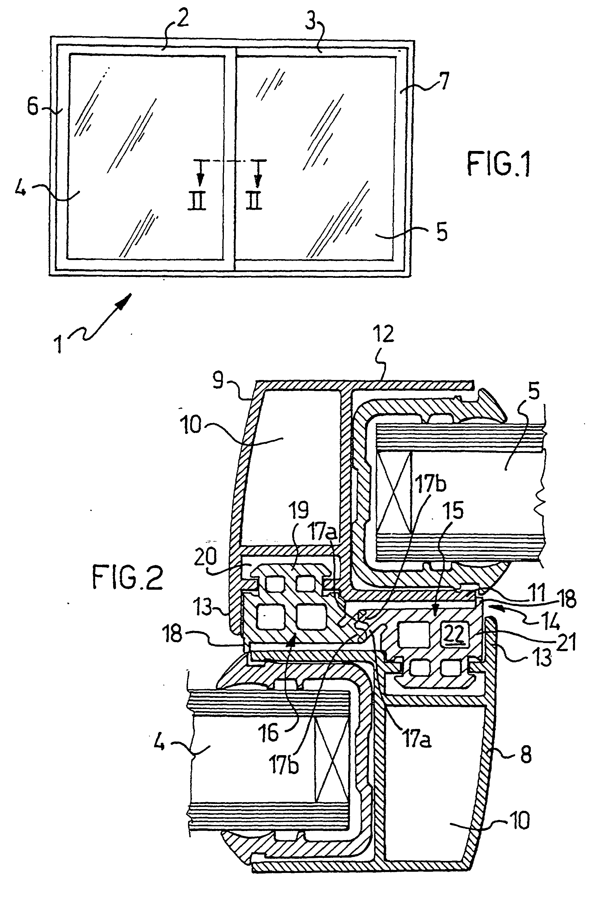
Figure 1 is a schematic elevational view of a window frame incorporating a matching
device according to the present invention, and
Figure 2 is a view of the matching device of Figure 1, sectioned on the line II, and
on an enlarged scale.
[0014] With reference to the appended drawings, a frame which, in the embodiment shown,
is a window frame, is generally indicated 1. The window frame 1 includes two sliding
windows 2 and 3 which have respective double panes 4 and 5 enclosed in respective
frames 6 and 7. The frames 6 and 7 are made of profiled sections and comprise, in
particular, respective profiled sections 8 and 9 which are intended to meet when the
windows 2 and 3 are in the closed position in the window frame.
[0015] The profiled sections 8 and 9 are identical and are arranged in opposed positions.
[0016] Each profiled section comprises a box-like body 10 projecting from which there are
two flanges 11 and 12 holding the respective double pane, and a transverse flange
13.
[0017] The window frame 1 comprises a matching device 14 for the profiled sections 8 and
9 of the windows 2 and 3 when the windows are in the closed position.
[0018] The matching device 14 according to the invention comprises two profiled strips,
indicated 15 and 16, respectively, each associated with a respective profiled section
8 or 9.
[0019] When the sliding windows 1 and 3 are in the closed position in the frame 1, the two
profiled strips 15 and 16 of the matching device 14 are in mutual leaktight contact
under pressure.
[0020] The two profiled strips 15 and 16, which are identical and arranged in opposed positions,
are made of a thermally-insulating plastics material selected from elastomers constituted
by ethylene and propylene copolymers, such as DUTRAL (registered trade mark) and/or
similar materials.
[0021] Each profiled strip 15 (16) comprises a resiliently yielding lip 17a which is in
contact under pressure with a flat portion 17b of the other profiled strip 16 (15).
[0022] Each profiled strip 15 (16) associated with a profiled section 8 (9) advantageously
also comprises a resiliently yielding edging 18 which is in leaktight contact under
pressure with the transverse flange 13 of the other profiled section 9 (8).
[0023] At this point, it is easy to see that the matching device 14 according to the present
invention has, altogether, four leaktight pressure contact points, more precisely,
two leaktight pressure contacts between the edging 18 of the profiled strip carried
by each profiled section and the flange 11 of the other profiled section and two leaktight
pressure contacts between the lip 17a of each profiled strip and the flat portion
17b of the other profiled strip.
[0024] Each profiled strip 15, 16 of the matching device 14 is firmly fixed to the respective
profiled section 8 or 9 of the window by virtue of the fact that each profiled strip
15, 16 comprises a substantially mushroom-shaped appendage 19 which is engaged in
the manner of a press stud in a hammer-shaped recess 20 in the profiled section 8,
9.
[0025] Each profiled strip 15 or 16 has a body 21 with a substantially rectangular cross-section
which is housed between the box-like body 10 and the transverse flange 13 of the respective
profiled section. The appendage 19 projects from the body 21 towards the box-like
body 10, and the lip 17a and the flat portion 17b project from the body 21 towards
the transverse flange 13 of the other profiled section.
[0026] Each profiled strip 15 or 16 advantageously comprises a plurality of weight-reducing
cavities, all indicated 22, which, preferably, are of square cross-section and are
formed in the body 21 so as to confer on the cross-section of the profiled strip a
substantially cross-walled configuration, achieving low thermal conductivity.
[0027] The main advantage of the matching device according to the present invention lies
in its structural simplicity. It is in fact formed by few parts and allows the profiled
sections of the windows to be formed with a simple shape.
[0028] A further advantage of the matching device according to the present invention is
that it improves thermal insulation by virtue of the fact that the same elements which
ensure leaktightness also constitute a thermal break.
[0029] Finally, it should be noted that the matching device according to the present invention
can be installed quickly since the individual profiled strips which make up the matching
device are identical and can be fitted directly by the engagement of their appendages
in the manner of press studs in the recesses in the profiled sections.
[0030] Not the least advantage of the matching device according to the present invention
lies in its compactness. Moreover, it can be produced with an aesthetically pleasing
appearance.
[0031] Furthermore, it should be noted that the matching device according to the present
invention can be expected to have a practically indefinite operative life.
[0032] Naturally, in order to satisfy contingent and specific requirements, an expert in
the art may apply to the above-described device many modifications and variations
all of which, however, are included in the scope of protection of the invention as
defined by the following claims.
1. A matching device (14) for profiled sections (8, 9) of a sliding door or window (2,
3) when they are in the closed position in a frame (1), said matching device (14)
comprising two profiled strips (15, 16) each of which is associatable with a respective
profiled section (8, 9), the profiled strips (15, 16) being in mutual contact under
pressure when the door or window (2, 3) is brought into a closed position, the profiled
strips (15, 16) comprising a body (21) and being made of a thermally insulating material,
characterized in that the body (21) of the strips (8, 9) comprise a plurality of weight reducing cavities
(22) such that the cross-section of the profiled strips (15, 16) has a cross-walled
configuration achieving low thermal conductivity.
2. A matching device (14) according to Claim 1, characterized in that the two profiled strips (15, 16) are identical.
3. A matching device (14) according to Claim 1, characterized in that each profiled strip (15, 16) comprises a resiliently yielding lip (17a) which is,
in the closed position of the doors or windows (2, 3), in contact under pressure with
a portion (17b) of the other profiled strip (16, 15).
4. A matching device (14) according to Claim 3, characterized in that the profiled strip (15, 16) associatable with the profiled section (8, 9) of a door
or window (2, 3) comprises a resiliently yielding edge (18) which is, in the closed
position of the doors or windows (2, 3), in contact under pressure with the profiled
section ( 9 , 8) of the other door or window (3, 2).
5. A matching device (14) according to Claim 4, characterized in that each profiled strip (15, 16) comprises an appendage (19) which is engageable in a
recess (20) formed in the respective profiled section (8, 9).
6. A matching device (14) according to Claim 5, characterized in that the appendage (19) is engageable in the recess (20) in the manner of a press-stud.
7. A matching device (14) according to Claim 1, wherein the weight reducing cavities
(22) are of square cross-section.
8. A matching device (14) according to claim 1, wherein the profiled strips (15, 16)
are made of thermally insulating plastics material.
9. A matching device (14) according to Claim 8, characterized in that the thermally insulating plastics material is selected from elastomers constituted
by ethylene and propylene copolymers.
10. A matching device (14) according to any one of the preceding claims, whereby the two
profiled strips (15, 16) are of identical crosssection and arrangeable in opposed
positions, each profiled strip (15; 16) further comprising:
- a resiliently yielding lip (17a) which is in contact under pressure with a flat
portion (17b) of the other profiled strip (16; 15) when the door or window (2, 3)
is brought into a closed position;
- a resiliently yielding edging (18) which is in leaktight contact under pressure
with a transverse flange (13) of the other profiled strip (16; 15) when the door or
window (2, 3) is brought into a closed position, providing the matching device (14)
with four leaktight pressure contact points.
11. A profiled strip (15,16) for a matching device (14) for two profiled sections (8,
9) of a sliding door or window (2, 3) when they are in the closed position in a frame
(1), the profiled strip (15, 16) comprising a body (21) and being made of a thermally
insulating material, characterized in that the body (21) of the strips (8, 9) comprise a plurality of weight reducing cavities
(22) such that the cross-section of the profiled strips (15, 16) has a cross-walled
configuration achieving low thermal conductivity.
12. A profiled strip (15, 16) according to claim 11, made of thermally insulating plastics
material.
13. A profiled strip (15, 16) according to Claim 12, characterized in that the plastics material is selected from elastomers constituted by ethylene and propylene
copolymers.
14. Frame (6, 7) for sliding doors or windows (2, 3) comprising identical profiled sections
(8, 9) which meet when doors or windows (2, 3) are in a closed position and a matching
device (14) according to any one of claims 1 to 10.
15. Frame (6, 7) according to claim 14, wherein the profiled sections (8, 9) comprise
a box-like body (10) with two projecting flanges (11, 12) holding the panes of the
doors or windows (2, 3) and a transverse flange (13), the body (21) of each profiled
strip (15, 16) being housed between said box-like body (10) and said transverse flange
(13) of the respective profiled section (8, 9).
1. Passvorrichtung (14) für Profilabschnitte (8, 9) einer Schiebetür oder eines Schiebefensters
(2, 3), wenn sie sich in der geschlossenen Position in einem Rahmen (1) befinden,
wobei die Passvorrichtung (14) zwei Profilleisten (15, 16) umfasst, von denen jede
mit einem entsprechenden Profilabschnitt (8, 9) verbunden werden kann, und die Profilleisten
(15, 16) unter Druck in Kontakt miteinander sind, wenn die Tür bzw. das Fenster (2,
3) in eine geschlossene Position gebracht ist, und die Profilleisten (15, 16) einen
Körper (21) umfassen und aus einem wärmeisolierenden Material bestehen, dadurch gekennzeichnet, dass der Körper (21) der Leisten (8, 9) eine Vielzahl gewichtsverringemder Hohlräume (22)
umfasst, so dass der Querschnitt der Profilleisten (15, 16) eine Gitterwandstruktur
hat, die geringe Wärmeleitfähigkeit bewirkt.
2. Passvorrichtung (14) nach Anspruch 1, dadurch gekennzeichnet, dass die zwei Profilleisten (15, 16) identisch sind.
3. Passvorrichtung (14) nach Anspruch 1, dadurch gekennzeichnet, dass jede Profilleiste (15, 16) eine elastisch nachgebende Lippe (17a) umfasst, die in
der geschlossenen Position der Türen bzw. Fenster (2, 3) unter Druck in Kontakt mit
einem Abschnitt (17b) der anderen Profilleiste (16, 15) ist.
4. Passvorrichtung (14) nach Anspruch 3, dadurch gekennzeichnet, dass die Profilleiste (15, 16), die mit dem Profilabschnitt (8, 9) einer Tür bzw. eines
Fensters (2, 3) in Verbindung gebracht werden kann, eine elastisch nachgebende Kante
(18) umfasst, die in der geschlossenen Position der Türen bzw. Fenster (2, 3) unter
Druck in Kontakt mit dem Profilabschnitt (9, 8) des anderen Fensters bzw. der anderen
Tür (3, 2) ist.
5. Passvorrichtung (14) nach Anspruch 4, dadurch gekennzeichnet, dass jede Profilleiste (15, 16) einen Ansatz (19) umfasst, der mit einer Aussparung (20)
in Eingriff gebracht werden kann, die in dem jeweiligen Profilabschnitt (8, 9) ausgebildet
ist.
6. Passvorrichtung (14) nach Anspruch 5, dadurch gekennzeichnet, dass der Ansatz (19) wie ein Pressbolzen mit der Aussparung (20) in Eingriff gebracht
werden kann.
7. Passvorrichtung (14) nach Anspruch 1, wobei die gewichtsverringemden Hohlräume (22)
quadratischen Querschnitt haben.
8. Passvorrichtung (14) nach Anspruch 1, wobei die Profilleisten (15, 16) aus wärmeisolierendem
Kunststoffmaterial bestehen.
9. Passvorrichtung (14) nach Anspruch 8, dadurch gekennzeichnet, dass das wärmeisolierende Kunststoffmaterial aus Elastomeren ausgewählt wird, die durch
Ethylen- und Propylen-Copolymere gebildet werden.
10. Passvorrichtung (14) nach einem der vorangehenden Ansprüche, wobei die zwei Profilleisten
(15, 16) identischen Querschnitt haben und an einander gegenüberliegenden Positionen
angeordnet werden können, wobei jede Profilleiste (15; 16) des Weiteren umfasst:
eine elastisch nachgebende Lippe (17a), die unter Druck in Kontakt mit einem flachen
Abschnitt (17b) der anderen Profilleiste (16; 15) ist, wenn die Tür bzw. das Fenster
(2, 3) in eine geschlossene Position gebracht ist;
eine elastisch nachgebende Kante (18), die unter Druck in dichtem Kontakt mit einem
Querflansch (13) der anderen Profilleiste (16; 15) ist, wenn die Tür bzw. das Fenster
(2, 3) in eine geschlossene Position gebracht ist, und die die Passvorrichtung (14)
mit vier dichten Druckkontaktpunkten versieht.
11. Profilleiste (15, 16) für eine Passvorrichtung (14) für zwei Profilabschnitte (8,
9) einer Schiebetür oder eines Schiebefensters (2,3), wenn sie sich in der geschlossenen
Position in einem Rahmen (1) befinden, wobei die Profilleiste (15, 16) einen Körper
(21) umfasst und aus einem wärmeisolierenden Material besteht, dadurch gekennzeichnet, dass der Körper (21) der Leisten (8, 9) eine Vielzahl gewichtsverringernder Hohlräume
(22) umfasst, so dass der Querschnitt der Profilleisten (15, 16) eine Gitterwandstruktur
hat, die geringe Wärmeleitfähigkeit bewirkt.
12. Profilleiste (15, 16) nach Anspruch 11, die aus wärmeisolierendem Kunststoffmaterial
besteht.
13. Profilleiste (15, 16) nach Anspruch 12, dadurch gekennzeichnet, dass das Kunststoffmaterial aus Elastomeren ausgewählt wird, die durch Ethylen- und Propyten-Copolymere
gebildet werden.
14. Rahmen (6, 7) für Schiebetüren oder -fenster (2, 3), der identische Profilabschnitte
(8, 9), die aufeinander treffen, wenn sich die Türen bzw. Fenster (2, 3) in einer
geschlossenen Position befinden, und eine Passvorrichtung (14) nach einem der Ansprüche
1 bis 10 umfasst.
15. Rahmen (6, 7) nach Anspruch 14, wobei die Profilabschnitte (8, 9) einen kastenartigen
Körper (10) mit zwei vorstehenden Flanschen (11, 12), die die Scheiben der Türen bzw.
Fenster (2, 3) halten, und einem Querflansch (13) umfassen, wobei der Körper (21)
jeder Profilleiste (15, 16) zwischen dem kastenartigen Körper (10) und dem Querflansch
(13) des entsprechenden Profilabschnitts (8, 9) aufgenommen ist.
1. Dispositif coopérant (14) pour sections profilées (8, 9) d'une porte ou fenêtre coulissante
(2, 3) lorsqu'elles sont dans la position fermée dans un cadre (1), ledit dispositif
coopérant (14) comprenant deux bandes profilées (15, 16) chacune desquelles peut être
associée à une section profilée respective (8, 9), les bandes profilées (15, 16) étant
en contact mutuel sous pression lorsque la porte ou fenêtre (2, 3) est mise dans une
position fermée, les bandes profilées (15, 16) comprenant un corps (21) et étant faites
d'un matériau thermiquement isolant, caractérisé en ce que le corps (21) des bandes (8, 9) comprend une pluralité de cavités de réduction de
poids (22) telles que la section transversale des bandes profilées (15, 16) a une
configuration de parois croisées ayant une faible conductivité thermique.
2. Dispositif coopérant (14) selon la revendication 1, caractérisé en ce que les deux bandes profilées (15, 16) sont identiques.
3. Dispositif coopérant (14) selon la revendication 1, caractérisé en ce que chaque bande profilée (15, 16) comprend une lèvre cédante de façon résiliente (17a)
qui est, dans la position fermée des portes ou fenêtres (2, 3), en contact sous pression
avec une partie (17b) de l'autre bande profilée (16, 15).
4. Dispositif coopérant (14) selon la revendication 3, caractérisé en ce que la bande profilée (15, 16) pouvant être associée à la section profilée (8, 9) d'une
porte ou fenêtre (2, 3) comprend un bord cédant de façon résiliente (18) qui est,
dans la position fermée des portes ou fenêtres (2, 3), en contact sous pression avec
la section profilée (9, 8) de l'autre porte ou fenêtre (3, 2).
5. Dispositif coopérant (14) selon la revendication 4, caractérisé en ce que chaque bande profilée (15, 16) comprend un appendice (19) qui peut venir en prise
avec un retrait (20) formé dans la section profilée respective (8, 9).
6. Dispositif coopérant (14) selon la revendication 5, caractérisé en ce que l'appendice (19) peut venir en prise avec le retrait (20) de la manière d'un bouton
à pression.
7. Dispositif coopérant (14) selon la revendication 1, dans lequel les cavités de réduction
de poids (22) sont de section transversale carrée.
8. Dispositif coopérant (14) selon la revendication 1, dans lequel les bandes profilées
(15, 16) sont faites de matériau plastique thermiquement isolant.
9. Dispositif coopérant (14) selon la revendication 8, caractérisé en ce que le matériau plastique thermiquement isolant est sélectionné à partir d'élastomères
constitués par des copolymères d'éthylène et propylène.
10. Dispositif coopérant (14) selon l'une quelconque des revendications précédentes, dans
lequel les deux bandes profilées (15, 16) sont de section transversale identique et
peuvent être agencées dans des positions opposées, chaque bande profilée (15 ; 16)
comprenant en outre :
- une lèvre cédante de façon résiliente (17a) qui est en contact sous pression avec
une partie plate (17b) de l'autre bande profilée (16 ; 15) lorsque la porte ou fenêtre
(2, 3) est mise dans une position fermée ;
- une bordure cédante de façon résiliente (18) qui est en contact hermétique sous
pression avec une bride transversale (13) de l'autre bande profilée (16 ; 15) lorsque
la porte ou fenêtre (2, 3) est mise dans une position fermée, donnant au dispositif
coopérant (14) quatre points de contact de pression hermétiques.
11. Bande profilée (15, 16) pour un dispositif coopérant (14) pour deux sections profilées
(8, 9) d'une porte ou fenêtre coulissante (2, 3) lorsqu'elles sont dans la position
fermée dans un cadre (1), la bande profilée (15, 16) comprenant un corps (21) et étant
faite d'un matériau isolant thermiquement, caractérisé en ce que le corps (21) des bandes (8, 9) comprend une pluralité de cavités de réduction de
poids (22) telles que la section transversale des bandes profilées (15, 16) a une
configuration de parois croisées ayant une faible conductivité thermique.
12. Bande profilée (15, 16) selon la revendication 11, faite de matériau plastique isolant
thermiquement.
13. Bande profilée (15, 16) selon la revendication 12, caractérisée en ce que le matériau plastique est sélectionné à partir d'élastomères constitués par des copolymères
d'éthylène et propylène.
14. Cadre (6, 7) pour portes ou fenêtres coulissantes (2, 3) comprenant des sections profilées
identiques (8, 9) qui se rencontrent lorsque les portes ou fenêtres (2, 3) sont dans
une position fermée et un dispositif coopérant (14) selon l'une quelconque des revendications
1 à 10.
15. Cadre (6, 7) selon la revendication 14, dans lequel les sections profilées (8, 9)
comprennent un corps similaire à une boîte (10) avec deux brides en saillie (11, 12)
maintenant les vitres des portes ou fenêtres (2, 3) et une bride transversale (13),
le corps (21) de chaque bande profilée (15, 16) étant logé entre ledit corps similaire
à une boîte (10) et ladite bride transversale (13) de la section profilée respective
(8, 9).