| (19) |
 |
|
(11) |
EP 1 204 568 B1 |
| (12) |
EUROPEAN PATENT SPECIFICATION |
| (45) |
Mention of the grant of the patent: |
|
09.06.2004 Bulletin 2004/24 |
| (22) |
Date of filing: 06.03.2000 |
|
| (86) |
International application number: |
|
PCT/US2000/005758 |
| (87) |
International publication number: |
|
WO 2000/051911 (08.09.2000 Gazette 2000/36) |
|
| (54) |
CORNER SUPPORT POST
ECK-TRAGEELEMENT
MONTANT DE SUPPORT D'ENCOIGNURE
|
| (84) |
Designated Contracting States: |
|
AT BE CH CY DE DK ES FI FR GB GR IE IT LI LU MC NL PT SE |
| (30) |
Priority: |
04.03.1999 US 262321
|
| (43) |
Date of publication of application: |
|
15.05.2002 Bulletin 2002/20 |
| (73) |
Proprietor: Sonoco Development, Inc. |
|
Hartsville,
South Carolina 29550 (US) |
|
| (72) |
Inventor: |
|
- WIDMAN, Donald, E.
Nashville, TN 37207 (US)
|
| (74) |
Representative: Eder, Christian, Dipl.-Ing. |
|
Eder & Schieschke
Patentanwälte
Elisabethstrasse 34/II
80796 München
80796 München (DE) |
| (56) |
References cited: :
JP-A- 4 294 763
US-A- 5 328 033
|
US-A- 4 483 444
|
|
| |
|
|
|
|
| |
|
| Note: Within nine months from the publication of the mention of the grant of the European
patent, any person may give notice to the European Patent Office of opposition to
the European patent
granted. Notice of opposition shall be filed in a written reasoned statement. It shall
not be deemed to
have been filed until the opposition fee has been paid. (Art. 99(1) European Patent
Convention).
|
BACKGROUND OF THE INVENTION
[0001] The invention relates to a corner support post for the cushioning protection of a
product according to the preamble of claim 1.
[0002] In the packaging of heavy, bulky products, particularly home appliances, having easily
damaged exterior walls, such as washers, dryers, refrigerators, and the like, it is
a common procedure to provide support posts at and engaged with the vertical corners
of the appliance, and may extend to the full height thereof. A protective carton or
box is also normally provided to enclose the appliance and corner engaged support
posts. Such protective boxes can comprise as little as a wrap of heavy duty plastic
or other appropriate material, or a complete corrugated cardboard carton, with the
main purposes being to retain or assist in retaining the positioned support posts,
and to protect the exterior of the appliance against surface scratches and possible
exposure to the elements.
[0003] Support posts of the type herein involved are usually constructed of convolutely
wound paperboard tubes which are transversely formed to the desire post configuration.
Thus formed, the support posts provide both stacking strength where necessary and
lateral strength for the protecting and cushioning of the packaged product. Such protection
against lateral or transverse forces is particularly desirable in light of the forces
normally applied to the package during the handling and transport thereof, and the
necessity of accommodating such forces without affecting the vertical compressive
strength of the posts which, preferably, is sufficient to accommodate stacked products.
[0004] Two forms of known support or corner posts will be seen in the following U.S. patents,
commonly assigned with the present invention:
US-5,267,651-A
US-5,593,039-A
[0005] In both of these patents, the disclosed support posts, to maintain the strength thereof,
rely on a controlled collapsing of the cushioning bead to form multiple layers between
and in addition to the outer walls. In US-A-5 593 039 provision is made for the accommodation
of protrusions, such as a handle, on the appliance. However, in this patent, as the
major line of force will be directed along the space between the product and the side
of the enclosing box, there is a tendency for pressure on the front of the box to
shift the product away from the side of the box or wrap and reduce the ability of
the front bead to withstand pressure.
[0006] Further prior art according to the preamble of claim 1 is JP 04 294 763 A : here
is a corner support post known with two hollow sections in rectangular configuration.
SUMMARY OF THE INVENTION
[0007] The present invention is concerned with a corner post construction which further
advances the art in providing a structure particularly capable of maintaining an intimate
engagement with the corner of the appliance and the enclosing box to each side of
the corner. These problems are solved by the characterizing part of claim 1. The post
retains a high degree of both lateral and vertical compressive strength as laterally
directed compressive forces are applied against and cushioned by the post.
[0008] Structurally, the post is preferably formed from a wound paperboard tube which is
transversely configured to the desired post configuration.
[0009] The formed post may be of a length greater than the height of the product or appliance
to be packaged so as to accommodate vertical compressive loads, as in stacking, without
requiring a direct bearing of the load by the appliance. The post, vertically positioned
in use and engaging a corner and the two adjacent faces of the appliance forming the
corner, defines two full length and laterally adjacent hollow cushioning sections
adapted to engage respectively against the two corner-defining faces immediately adjacent
the corner and to extend outward therefrom to the encircling protective carton. The
sections include a first enlarged section of trapezoidal configuration and a second
smaller section of a generally square configuration. The sections are defined by a
first inner wall having a right angular offset area which embraces the appliance corner
and sufficiently overlaps a face of the appliance to transmit force received on an
outer parallel panel of the first section primarily to the appliance face to maintain
a stable relationship between the post and the appliance for maximum utilization of
the cushioning effect of the larger section. The post is further defined by a second
outer wall forming an inclined side or side panel of the larger trapezoidal section
and terminating, slightly beyond the appliance seating inner wall offset, in angularly
related wall panels or portions which define the smaller cushioning section. The relationship
between these sections is such as to cushion laterally applied forces while maintaining
the stability and strength of the post, in large part by retaining the basic tubular
configurations for the cushioning sections.
[0010] Other features of the invention will become apparent from the more detailed description
following hereinafter.
BRIEF DESCRIPTION OF THE DRAWINGS
[0011]
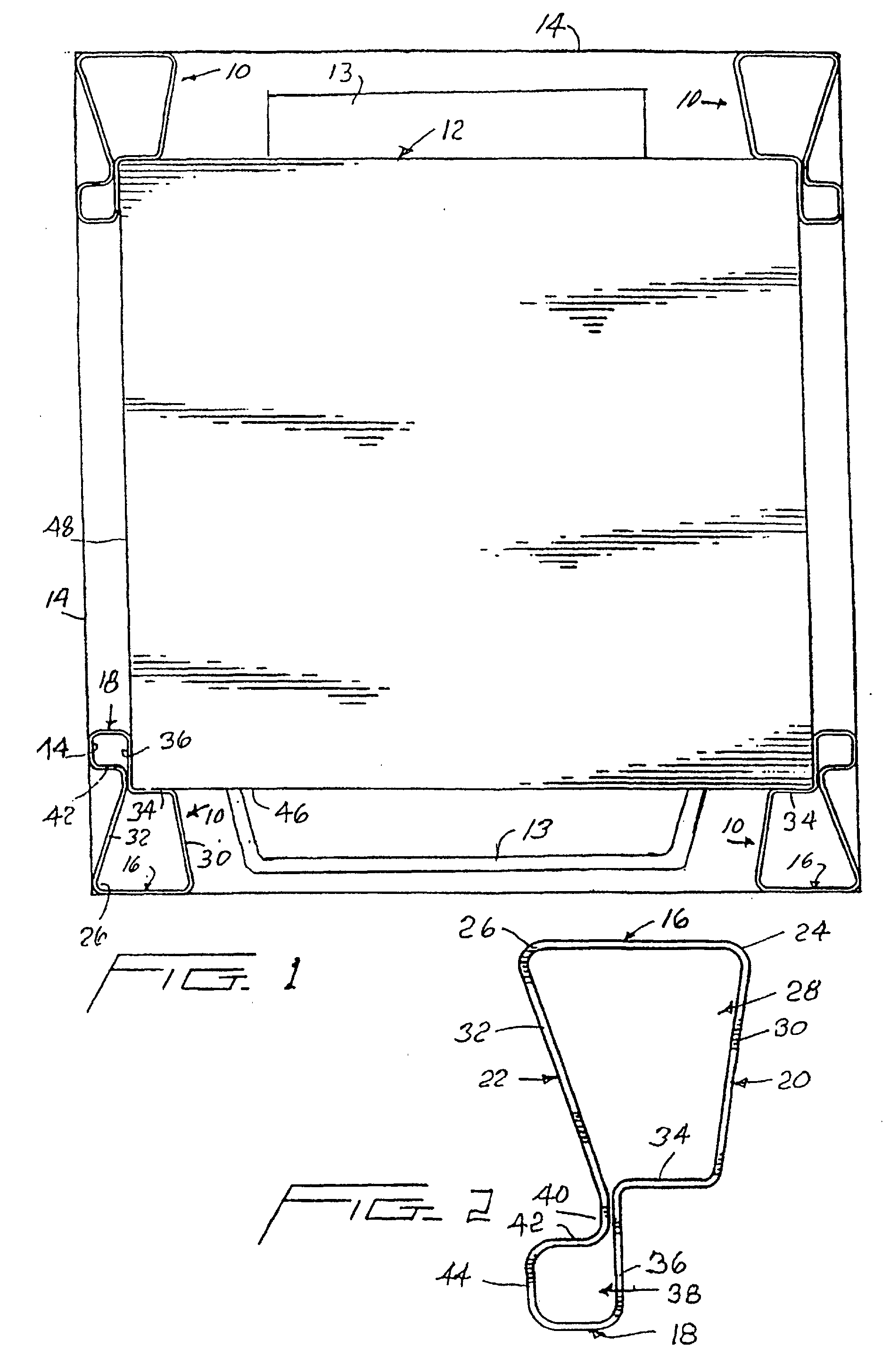
Figure 1 is a top plan view of a product package with the protective top cap removed
and illustrating the positioning of the corner support posts of the invention;
Figure 2 is an enlarged top plan view of the corner post;
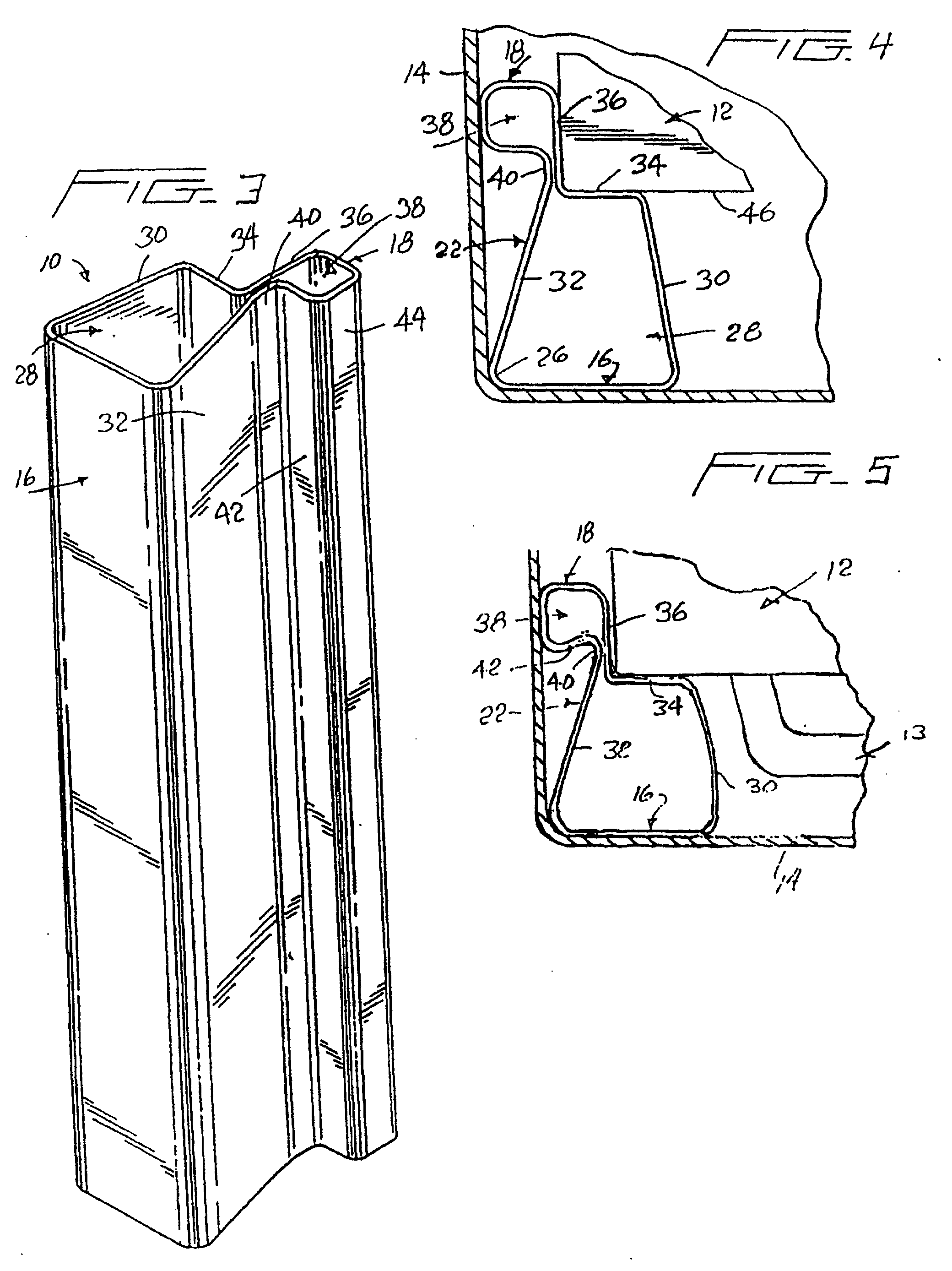
Figure 3 is an enlarged perspective view of the corner post;
Figure 4 is an enlarged cross-sectional detail illustrating the post mounted in position
between a product and surrounding support box prior to the introduction of any compressive
forces; and
Figure 5 is a similar view with the post under a lateral compressive loading.
DESCRIPTION OF PREFERRED EMBODIMENT
[0012] Referring now more specifically to the drawings, figure 1 illustrates four corner
support posts 10 engaging the corners of, and stabilizing, a product 12 within a packaging
carton or box 14. The packaging box 14 in turn stabilizes and retains the support
posts 10 in position to confine and cushion the product 12 and accommodate any protrusions,
such as a handle 13 thereon. The support posts will normally extend vertically between
a lower support platform and a top cap (not illustrated).
[0013] The support posts 10, preferably made from a wound paperboard tube formed to the
desired cross-sectional configuration, provides both longitudinal compressive strength
to allow for stacking, and an enhanced capability to cushion and accommodate lateral
compressive forces while maintaining effective stacking strength. More particularly,
the post 10 includes generally parallel first and second end walls 16 and 18 integrally
joined by first inner and second outer side walls 20 and 22.
[0014] The side walls 20 and 22 extend from the opposed ends of the end wall 16, each at
an acute inner angle thereto to form outer corners 24 and 26 of both the post and
a first large, full length, hollow outer support and cushioning section 28. The opposed
sides of the section 28 comprise side wall panels 30 and 32 defined by the converging
side walls 20 and 22 respectively. The first larger section 28 is completed by a right
angular offset formed in said first side wall 20 and defining a laterally directed
inner end panel 34 extending, substantially parallel to the end wall 16, across the
narrow end of the section 28 defined by the converging side panels 30 and 32. Thus
formed, the first section 28 is of a trapezoidal configuration.
[0015] The first side wall 20 continues from the inner end panel 34, at right angles thereto,
to one edge of the second end wall 18, thereby defining a side panel 36 of a second
smaller inner section 38. The side wall 22, beyond the laterally extending inner end
panel 34 of the section 28, parallels the first side wall 20 immediately adjacent
thereto at a small transition area 40 between the sections whereat a sliding relationship
is provided between the side walls as shall be referred to subsequently. Immediately
beyond this transition area 40, the side wall 22 is laterally outwardly directed,
relative to the side wall 20, to define an inner panel 42 of the second smaller section
38 which generally parallels the end wall 18. The side wall 22, at the outer end of
the laterally directed end panel 42, extends at substantially right angles to the
end panel 42 and defines a second side panel 44, generally parallel to side panel
36, which integrally joins, at approximately a right angle thereto, the end wall 18,
thereby completing the generally square or rectangular configuration of the smaller
section 38.
[0016] The second side panel 44 of the section 38 is substantially linearly aligned with
the outer corner 26 of the first section 28 defined by the first section side panel
32 and end wall 16.
[0017] The first side panel 36 of the small section 38 is in a plane generally aligned with
a corner of the larger section defined by the wall panel 32 and inner end panel 34
of this larger section. As such, the side panel 36 is in a plane offset from the central
plane of the section 28 closer to the second post side wall 22. This is significant
in that upon the introduction of an external force to the end wall 16, a major component
of this force will be transmitted directly to the face 46 of the product or appliance
12 against which the inner end panel 34 seats, rather than along the adjoining right
angle face 48 which would tend to cause a tipping away of the post from the first
face 46, a reduced resistance to collapsing of the first section of the post, and
a possible reduction in the lateral protection along the side of the product.
[0018] With reference to figures 4 and 5, it will be seen that the larger section 28, when
subjected to a lateral compressive force acting on the outer end wall 16 and the opposed
inner end panel 34, normally when the package is being moved, will provide a predetermined
cushioning resistance with the side panel 30 bowing outward in a controlled manner.
Basically the load of the product 12 moving relative toward the outer end wall 16
of the post, will cause a controlled outward arcuate bending or bowing of the inclined
side panel 30. Such an outward bowing is encouraged by locating the relatively shorter
end panel 34 generally centrally aligned with the longer end wall 16 whereby the main
resultant component of the force resulting from movement of the product relative to
the box front wall is inward of the inclined panel 30.
[0019] Any excess loading force beyond that anticipated and normally accommodated by the
controlled bending of the side panel 30 will tend to be dissipated along the side
and toward smaller section 38. Under such excess loading, the side panel 36 of the
smaller section 38 tends to move toward the end wall 16, sliding relative to the post
side wall 22 at the transition area 40 and causing a slight change in the rectangular
configuration of the smaller section 38, while retaining the general overall volume
and position thereof between the product and sleeve, thus preserving the lateral and
longitudinal strength thereof for both cushioning and support.
[0020] It will also be noted that the larger section 28 is retained as a hollow tubular
bead firmly engaged within the corner of the outer protective box and with the corresponding
corner of the product to retain substantial lateral and longitudinal strength and
a continued cushioned protection of the product even under extreme conditions. The
inner end panel 34 remains in intimate contact with the product and continues to provide
a cradle-like support allowing for slight shifting of the product without damage thereto.
Incidentally, the two post walls 20 and 22 will normally be in actual sliding engagement
with each other at the transition area 40. The slight spacing shown in the drawings
is for illustrative purposes only although the inherent flexible resilient nature
of the material of the post may in fact cause such a spacing.
[0021] The foregoing is considered illustrative of the features of the invention. As variations
of the described embodiment may occur to those knowledgeable in the art, the invention
is to be limited only by the scope of the claims appearing hereinafter.
1. A corner support post (10) for the cushioning protection of a packaged product (12),
said support post (10) having a length and a width and being defined by a continuous
wall structure, said post (10), across the width thereof, comprising inner and outer
transversely aligned substantially coextensive hollow sections (28, 38) extending
along the length of said post (10), characterized in that the first section (28) is of trapezoidal configuration with parallel inner and outer
end panels (16, 34) and converging side panels (30, 32) defined by said wall structure,
and that the second portion (38) is of rectangular configuration defined by said wall
structure and extending laterally and longitudinally beyond said inner end panel (34)
of said first section (28).
2. The corner support post of claim 1, characterized in that said first section (28) is of generally trapezoidal configuration with side panels
(30, 32), defined by first and second side walls (20, 22), converging from a first
end wall (16), an inner end panel (34) defined by said first side wall (20) and extending
laterally toward said second side wall (20), said inner end panel (34) being parallel
to and spaced from said first end wall (16) and aligned generally centrally thereof,
said second section (38) being of a generally rectangular configuration with opposed
first and second side panels (36, 44) respectively defined by said first and second
side walls and extending from an end wall (18), said second section (38) including
an inner end panel (42) defined by said second side wall (44) and extending laterally
away from said side panel (36).
3. The corner support post of claim 1, characterized in that an outer end panel (16) of said first section (28) defines the lateral extent of
said post (10), said second section (38) being within the lateral extent defined by
said outer end panel (16).
4. The corner support post of claim 2, characterized in that said second section (38) includes the side panel (36) defined by said wall structure
and extending at substantially a right angle from said inner end panel (34) of said
first section (28).
5. The corner support post of claim 1, characterized in that said end walls (16, 18) and inner end panels (34, 42) are substantially parallel
to each other.
6. The corner support post of claim 5, characterized in that said inner end panel (34) of said outer section (28) and said second side panel (36)
of said second section (38) define a substantially right angle.
7. The corner support post of claim 1, characterized in that a second side panel (30) of said second side wall is linear, generally perpendicular
to said first end wall (16), and aligned with side panel (32) at the included angle
with said first end wall (16).
8. The corner support post of claim 1, characterized in that said first end wall (16) is of a predetermined length, said inner end panel (34)
of said first section (28) being of a lesser length and aligned generally centrally
of said first end wall (16).
9. The corner support post of claim 8, characterized in that said inner end panel (34) of said first section (28) has an end laterally adjacent
said second side panel (36), said second side panel (36) of said second section (38)
extending to said end of said first section inner end panel (34).
10. The corner support post of claim 1, characterized in that said first section (28) is of a predetermined volumetric size and said second section
(3 8) is of a smaller volumetric size.
11. The corner support post of claim 1, characterized in that said first section (28) is defined longitudinally and laterally beyond said inner
end panel (34) of said first section (28).
1. Eckenstütze (10), um ein verpacktes Produkt (12) gepuffert zu schützen, wobei die
Stütze (10) eine Länge und eine Breite hat und durch eine kontinuierliche Wandstruktur
definiert ist, wobei die Stütze (10) über ihre Breite innere und äußere, quer ausgerichtete,
sich im Wesentlichen gemeinsam erstreckende hohle Bereiche (28, 38) aufweist, die
sich entlang der Länge der Stütze (10) erstrecken, dadurch gekennzeichnet, dass der erste Bereich (28) trapezförmig ausgebildet ist, mit parallelen inneren und äußeren
Endplatten (16, 34) und konvergierenden Seitenplatten (30, 32), die durch die Wandstruktur
definiert sind, und dass der zweite Bereich (38) eine rechteckige Form hat, die durch
die Wandstruktur definiert ist, und sich seitlich und in Längsrichtung über die innere
Endplatte (34) des ersten Bereichs (28) hinaus erstreckt.
2. Eckenstütze nach Anspruch 1, dadurch gekennzeichnet, dass der erste Bereich (28) im Allgemeinen trapezförmig ausgebildet ist, mit Seitenplatten
(30, 32), die durch die ersten und zweiten Seitenwände (20, 22) definiert sind und
von einer ersten Endwand (16) konvergieren, und mit einer inneren Endplatte (34),
die durch die erste Seitenwand (20) definiert ist und sich seitlich zur zweiten Seitenwand
(20) erstreckt, wobei die innere Endplatte (34) zur ersten Endwand (16) parallel und
von dieser beabstandet ist und im Allgemeinen mittig zu dieser ausgerichtet ist, wobei
der zweite Bereich (38) im Allgemeinen rechteckig ausgebildet ist, mit gegenüberliegenden
ersten und zweiten Seitenplatten (36, 44), die jeweils durch die ersten und zweiten
Seitenwände definiert sind und sich von einer Endwand (18) erstrecken, wobei der zweite
Bereich (38) eine innere Endplatte (42) aufweist, die durch die zweite Seitenwand
(44) definiert ist und sich seitlich von der Seitenplatte (36) erstreckt.
3. Eckenstütze nach Anspruch 1, dadurch gekennzeichnet, dass eine äußere Endplatte (16) des ersten Bereichs (28) die seitliche Ausdehnung der
Stütze (10) definiert, wobei der zweite Bereich (38) innerhalb der seitlichen Ausdehnung
liegt, die durch die äußere Endplatte (16) definiert ist.
4. Eckenstütze nach Anspruch 2, dadurch gekennzeichnet, dass der zweite Bereich (38) die Seitenplatte (36) aufweist, die durch die Wandstruktur
definiert wird und sich im Wesentlichen im rechten Winkel von der inneren Endplatte
(34) des ersten Bereichs (28) erstreckt.
5. Eckenstütze nach Anspruch 1, dadurch gekennzeichnet, dass die Endwände (16, 18) und die inneren Endplatten (34, 42) im Wesentlichen parallel
zueinander sind.
6. Eckenstütze nach Anspruch 5, dadurch gekennzeichnet, dass die innere Endplatte (34) des äußeren Bereichs (28) und die zweite Seitenplatte (36)
des zweiten Bereichs (38) im Wesentlichen einen rechten Winkel definieren.
7. Eckenstütze nach Anspruch 1, dadurch gekennzeichnet, dass eine zweite Seitenplatte (30) der zweiten Seitenwand linear, im Allgemeinen rechtwinklig
zur ersten Endwand (16) und in dem mit der ersten Endwand (16) eingeschlossenen Winkel
auf die Seitenplatte (32) ausgerichtet ist.
8. Eckenstütze nach Anspruch 1, dadurch gekennzeichnet, dass die erste Endwand (16) eine vorherbestimmte Länge hat, wobei die innere Endplatte
(34) des ersten Bereichs (28) eine geringere Länge hat und im Allgemeinen mittig zur
ersten Endwand (16) ausgerichtet ist.
9. Eckenstütze nach Anspruch 8, dadurch gekennzeichnet, dass die innere Endplatte (34) des ersten Bereichs (28) ein Ende besitzt, das der zweiten
Seitenplatte (36) seitlich benachbart ist, wobei die zweite Seitenplatte (36) des
zweiten Bereichs (38) sich zu dem Ende der inneren Endplatte (34) des ersten Bereichs
erstreckt.
10. Eckenstütze nach Anspruch 1, dadurch gekennzeichnet, der erste Bereich (28) eine vorherbestimmte volumetrische Größe hat und der zweite
Bereich (38) eine kleinere volumetrische Größe hat.
11. Eckenstütze nach Anspruch 1, dadurch gekennzeichnet, dass der erste Bereich (28) in Längsrichtung und seitlich über die innere Endplatte (34)
des ersten Bereichs (28) hinaus definiert ist.
1. Montant de support d'encoignure (10) pour la protection amortissante d'un produit
emballé (12), ledit montant de support (10) ayant une longueur et une largeur et étant
défini par une structure de paroi continue, ledit montant (10), sur sa largeur, comprenant
des sections creuses sensiblement coextensives transversalement alignées intérieure
et extérieure (28, 38) s'étendant suivant la longueur dudit montant (10), caractérisé en ce que la première section (28) a une configuration trapézoïdale avec des panneaux d'extrémité
intérieur et extérieur parallèles (16, 34) et des panneaux latéraux convergents (30,
32) définis par ladite structure de paroi, et en ce que la seconde partie (38) a une configuration rectangulaire définie par ladite structure
de paroi et s'étendant latéralement et longitudinalement au-delà dudit panneau d'extrémité
intérieur (34) de ladite première section (28).
2. Montant de support d'encoignure selon la revendication 1, caractérisé en ce que ladite première section (28) a une configuration globalement trapézoïdale avec des
panneaux latéraux (30, 32), définie par des première et seconde parois latérales (20,
22), convergeant à partir d'une première paroi d'extrémité (16), un panneau d'extrémité
intérieur (34) défini par ladite première paroi latérale (20) et s'étendant latéralement
vers ladite seconde paroi latérale (20), ledit panneau d'extrémité intérieur (34)
étant parallèle à et espacé de ladite première paroi d'extrémité (16) et aligné globalement
au centre de celle-ci, ladite seconde section (38) ayant une configuration globalement
rectangulaire avec des premier et second panneaux latéraux opposés (36, 44) définis
respectivement par lesdites première et seconde parois latérales et s'étendant à partir
d'une paroi d'extrémité (18), ladite seconde section (38) comprenant un panneau d'extrémité
intérieur (42) défini par ladite seconde paroi latérale (44) et s'étendant latéralement
à distance dudit panneau latéral (36).
3. Montant de support d'encoignure selon la revendication 1, caractérisé en ce qu'un panneau d'extrémité extérieur (16) de ladite première section (28) définit l'étendue
latérale dudit montant (10), ladite seconde section (38) étant à l'intérieur de l'étendue
latérale définie par ledit panneau d'extrémité extérieur (16).
4. Montant de support d'encoignure selon la revendication 2, caractérisé en ce que ladite seconde section (38) comprend le panneau latéral (36) défini par ladite structure
de paroi et s'étendant sensiblement à angle droit par rapport audit panneau d'extrémité
intérieur (34) de ladite première section (28).
5. Montant de support d'encoignure selon la revendication 1, caractérisé en ce que lesdites parois d'extrémité (16, 18) et lesdits panneaux d'extrémité intérieurs (34,
42) sont sensiblement parallèles les uns aux autres.
6. Montant de support d'encoignure selon la revendication 5, caractérisé en ce que ledit panneau d'extrémité intérieur (34) de ladite section extérieure (28) et ledit
second panneau latéral (36) de ladite seconde section (38) définissent un angle sensiblement
droit.
7. Montant de support d'encoignure selon la revendication 1, caractérisé en ce qu'un second panneau latéral (30) de ladite seconde paroi latérale est linéaire, globalement
perpendiculaire à ladite première paroi d'extrémité (16), et aligné avec le panneau
latéral (32) à l'angle inclus avec ladite première paroi d'extrémité (16).
8. Montant de support d'encoignure selon la revendication 1, caractérisé en ce que ladite première paroi d'extrémité (16) a une longueur prédéterminée, ledit panneau
d'extrémité intérieur (34) de ladite première section (28) ayant une longueur moindre
et étant aligné globalement au centre de ladite première paroi d'extrémité (16).
9. Montant de support d'encoignure selon la revendication 8, caractérisé en ce que ledit panneau d'extrémité intérieur (34) de ladite première section (28) a une extrémité
latéralement adjacente audit second panneau latéral (36), ledit second panneau latéral
(36) de ladite seconde section (38) s'étendant vers ladite extrémité dudit panneau
d'extrémité intérieur (34) de la première section.
10. Montant de support d'encoignure selon la revendication 1, caractérisé en ce que ladite première section (28) a une taille volumétrique prédéterminée et ladite seconde
section (38) a une taille volumétrique inférieure.
11. Montant de support d'encoignure selon la revendication 1, caractérisé en ce que ladite première section (28) est définie longitudinalement et latéralement au-delà
dudit panneau d'extrémité intérieur (34) de ladite première section (28).