|
(11) | EP 1 256 019 B1 |

| (12) | EUROPEAN PATENT SPECIFICATION |
|
|
| (54) |
METHOD FOR DETERMINING THE NATURE OF SUBTERRANEAN RESERVOIRS METHODE ZUR BESTIMMUNG DER NATUR EINES UNTERIRDISCHEN RESERVOIRS PROCEDE POUR DETERMINER LA NATURE DE RESERVOIRS SOUTERRAINS |
|
|
|||||||||||||||||||||||||||||||||||
| Note: Within nine months from the publication of the mention of the grant of the European patent, any person may give notice to the European Patent Office of opposition to the European patent granted. Notice of opposition shall be filed in a written reasoned statement. It shall not be deemed to have been filed until the opposition fee has been paid. (Art. 99(1) European Patent Convention). |
[0001] The present invention relates to a method for determining the nature of submarine and subterranean reservoirs. The invention is particularly suitable for determining whether a reservoir, whose approximate geometry and location are known, contains hydrocarbons or water, though it can also be applied to detecting reservoirs with particular characteristics.
[0002] Currently, the most widely used techniques for geological surveying, particularly in sub-marine situations, are seismic methods. These seismic techniques are capable of revealing the structure of the subterranean strata with some accuracy. However, whereas a seismic survey can reveal the location and shape of a potential reservoir, it cannot reveal the nature of the reservoir.
[0003] The solution therefore is to drill a borehole into the reservoir. However, the costs involved in drilling an exploration well tend to be in the region of £25m and since the success rate is generally about 1 in 10, this tends to be a very costly exercise.
[0004] It is therefore an object of the invention to provide a system for determining, with greater certainty, the nature of a subterranean reservoir without the need to sink a borehole.
[0005] WO 00/00850A discloses a system for monitoring the resistivity in strata close to a well bore. Both the EM source and receivers are located in the well bore. The system is concerned only with a situation close to the well bore and therefore uses high frequency transmissions.
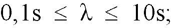
[0006] According to the invention, there is provided a method of performing a survey of subterranean strata in order to search for a hydrocarbon containing subterranean reservoir, or to determining the nature of a submarine or subterranean reservoir whose approximate geometry and location are known, which comprises: applying a time varying electromagnetic field to the subterranean strata; detecting the electromagnetic wave field response; seeking, in the wave field response, a component representing a refracted wave; and determining the presence and/or nature of any reservoir identified based on the presence or absence of a refracted wave component; in which the transmitted field is in the form of a wave, and in which the distance between the transmitter and a receiver is given by the formula
where X is the wavelength of the transmission through the overburden (34) and l is the distance between the transmitter (37) and the receiver (38).
[0007] Given that the distances and the geometry of the reservoir will be known from previous seismic surveys, an optimum λ and l would be selected.
[0008] It has been appreciated by the present applicants that while the seismic properties of oil-filled strata and water-filled strata do not differ significantly, their electromagnetic resistivities (permittivities) do differ. Thus, by using an electromagnetic surveying method, these differences can be exploited and the success rate in predicting the nature of a reservoir can be increased significantly. This represents potentially an enormous cost saving.
[0009] The present invention arises from an appreciation of the fact that when an EM field is applied to subterranean strata which include a reservoir, in addition to a direct wave component and a reflected wave component from the reservoir, the detected wave field response will include a " refracted" wave component from the reservoir. The reservoir containing hydrocarbon is acting in some way as a wave guide. For the purposes of this specification, however, the wave will be referred to as a "refracted wave" , regardless of the particular mechanism which in fact pertains.
[0010] Be that as it may, a refracted wave behaves differently, depending on the nature of the stratum in which it is propagated. In particular, the propagation losses in hydrocarbon stratum are much lower than in a water-bearing stratum while the speed of propagation is much higher. Thus, when an oil-bearing reservoir is present, and an EM field is applied, a strong and rapidly propagated refracted wave can be detected. This may therefore indicate the presence of the reservoir or its nature if its presence is already known. Preferably, therefore, the method according to the invention further includes the step of analyzing the effects on any detected refracted wave component that have been caused by the reservoir in order to determine further the content of the reservoir based on the analysis.
[0011] Preferably, the applied electromagnetic field is polarized. Preferably, the polarization is such as if created by in-line horizontal transmitter and receiver antennas.
[0012] If the offset between the transmitter and receiver is significantly greater than three times the depth of the reservoir from the seabed (i.e. the thickness of the overburden), it will be appreciated that the attenuation of the refracted wave will often be less than that of direct wave and the reflected wave. The reason for this is the fact that the path of the refracted wave will be effectively distance from the transmitter down to the reservoir i.e. the thickness of the overburden, plus the offset along the reservoir, plus the distance from the reservoir up to the receivers i.e. once again the thickness of the overburden.
[0013] The polarization of the source transmission will determine how much energy is transmitted into the oil-bearing layer in the direction of the receiver. A dipole antenna is therefore the preferred transmitter, though any transmetter capable of generating an appropriate polarized field can be used. In general, it is preferable to adopt a dipole with a large effective length. The transmitter dipole may therefore be 100 to 1000 meters in length, and may be 10 to 1000 meters preferably cross-polarized. The receiver Dipole optimum length is determined by the thickness of the overburden.
[0014] The technique is applicable in exploring land-based subterranean reservoirs but is especially applicable to submarine, in particular sub-sea, subterranean reservoirs. In a preferred application, the transmitter(s) and/or receivers are located on or close to the seabed or the bed of some other area of water. Conveniently, there will be a single transmitter and an array of receivers, the transmitter(s) and receivers being dipole antennae or coils, though other forms of transmitter/receivers can be used. The transmitter may be in an existing well. Also, if improved directionality of the emitted field is desirable, then a plurality of transmitters with phase adjustment can be used.
[0015] In one arrangement, a single transmitter and several receivers are arranged on a single cable which is laid in the required position on the seabed by a surface or submarine vessel. These can then be moved to another location. In a second arrangement, several receivers have fixed positions on the seabed. The transmitter can be moved to different locations. In a third arrangement, a transmitter may be positioned by a first vessel while a second vessel positions one or more receivers. This affords flexibility in the positioning of both transmitter and receivers. In a fourth arrangement, that the transmitter be in an existing well while the receivers may constitute a fixed matrix or they may be movable.
[0016] It will be appreciated that the present invention may be used to determine the position, the extent, the nature and the volume of a particular stratum, and may also be used to detect changes in these parameters over a period of time.
[0017] Electromagnetic surveying techniques in themselves are known. However, they are not widely used in practice. In general, the reservoirs of interest are about 1 km or more below the seabed. In order to carry out electromagnetic surveying as a stand alone technique in these conditions, with any reasonable degree of resolution, short wavelengths are necessary. Unfortunately, such short wavelengths suffer from very high attenuation. Long wavelengths do not provide adequate resolution. For these reasons, seismic techniques are preferred.
[0018] However, while longer wavelengths applied by electromagnetic techniques cannot provide sufficient information to provide an accurate indication of the boundaries of the various strata, if the geological structure is already known, they can be used to determine the nature of a particular identified formation, if the possibilities for the nature of that formation have significantly differing electromagnetic characteristics. The resolution is not particularly important and so longer wavelengths which do not suffer from excessive attenuation can be employed.
[0019] The resistivity of seawater is about 0.3 ohm-m and that of the overburden beneath the seabed would typically be from 0.3 to 4 ohm-m, for example about 2 ohm-m. However, the resisitivty of an oil reservoir is likely to be about 20-300 ohm-m. This large difference can be exploited using the techniques of the present invention. Typically, the resisitvity of a hydrocarbon-bearing formation will be 20 to 300 times greater than water-bearing formation.
[0020] Due to the different electromagnetic properties of a gas/oil bearing formation and a water bearing formation, one can expect a reflection and refraction of the transmitted field at the boundary of a gas/oil bearing formation. However, the similarity between the properties of the overburden and a reservoir containing water means that no reflection or refraction is likely to occur.
[0021] The transmitted field may be pulsed, however, a coherent continuous wave with stepped frequencies is preferred. It may be transmitted for a significant period of time, during which the transmitter should preferably be stationary (although it could be moving slowly), and the transmission stable. Thus, the field may be transmitted for a period of time from 3 seconds to 60 minutes, preferably from 3 to 30 minutes, for example about 20 minutes. The receivers may also be arranged to detect a direct wave and a wave refracted from the reservoir, and the analysis may include extracting phase and amplitude data of the refracted wave from corresponding data from the direct wave.
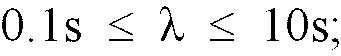
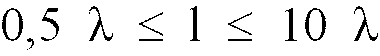
[0022] Preferably, the wavelength of the transmission is given by the formula
where λ is the wavelength of the transmission through the overburden and s is the distance from the seabed to the reservoir. More preferably λ is from about 0.5s to 2s. The transmission frequency may be from 0.01 Hz to 1 kHz. preferably from 1 to 20 Hz, for example 5 Hz.
[0023] In a preferred regime, a first transmission is made at a first frequency and received by each receiver in a tuned array of receivers, then a second transmission is made at a second frequency and received by the same tuned array of receivers, the receivers being tuned to receive their respective transmission. This would probably be repeated several more times, though it may only be carried out once.
[0024] Preferably, the analysis includes comparing the results of the measurements taken with the results of a mathematical simulation model based on the known properties of the reservoir and overburden conditions.
[0025] Preferably, the analyzing means is arranged to analyze phase and amplitude. The data can be analyzed using time domain and frequency domain techniques, and other pulse sharpening techniques. Thus, the data can be made to mimic seismic data so that conventional seismic post-processing techniques can be employed.
[0026] If a location of interest is considered, a mathematical modeling operation may be carried out. Thus, the various relevant parameters, such as depth and expected resistivities of the various known strata in the overburden are applied to the mathematical model and the expected results are calculated in dependence upon whether a formation under consideration is oil-bearing or water-bearing. The theoretically predicted results can then be compared with the actual results achieved in the field in order to determine the nature of the formation.
[0027] The present invention also extends to a method of surveying subterranean measures which comprises; performing a seismic survey to determine the geological structure of a region; and where that survey reveals the presence of a subterranean reservoir, subsequently performing a method as described above.
[0028] The invention may be carried into practice in various ways and some embodiments will now be described by way of example with reference to the accompanying drawings, in which: -
Figure 1 is a schematic diagram of an experimental technique verifying the principles of the invention.
Figure 2 is a schematic section of a system in accordance with the invention.
[0029] Figure 1 shows a test rig comprising a tank 11 filled with seawater and a simulated oil-bearing layer, in the form of a diaphragm 12 filled with fresh water. The diaphragm 12 is suspended above the bottom of the tank 11. A transmitter 13 and a receiver 14 are mounted on respective vertical posts 15, 16 suspended from a beam 17. The posts are at a constant spacing L and the transmitter 13 and receiver 14 are vertically movable up and down their posts 15, 16.
[0030] When the transmitter 13 and receiver 14 are in the position shown in solid lines, the sensitivity of the receiver is adjusted so that the attenuation in the seawater is such that the direct wave 18 cannot be detected. Clearly, the reflected wave 19 would also be attenuated so much that it also would not be detected, given the greater distance of travel through the sea water.
[0031] The transmitter 13 and receiver 14 are then lowered down together, and transmissions made at intervals. At a particular depth indicated in broken lines, the receiver 14' detected a strong signal following a transmission from the transmitter 13'. This could not be a direct wave, nor a reflected wave, due to the attenuation by the seawater. It was therefore concluded that the only path for the wave to have taken was through the diaphragm 12. This is shown as a refracted wave 21.
[0032] The distance traveled through the seawater is relatively short and while the wave traveled some way through the fresh water in the diaphragm 12, the attenuation was considerably less than it would have been through the same distance in seawater. Thus, the overall attenuation was less than that for the direct wave 18 and the refracted wave 21 was detected.
[0033] A more practical example is shown in Figure 2. The surface of the sea is shown at 31 with the sea 32 extending down to the ocean floor 33. There is an overburden 34, an oil-bearing layer 35 and lower layer 36. This structure is known from seismic surveys, but the nature of the layers is not known. A transmitter is shown schematically at 37 on the ocean floor 33 and a receiver similarly at 38. They are spaced apart by an offset 39.
[0034] The transmitter 37 is in the form of a dipole antenna which is arranged to transmit an electromagnetic wave polarized in such a way that the radial E component is generally along the line to receiver. This results in a direct wave 41 being propagated in the sea water along the surface of the overburden and a reflected wave 42a and 42b which proceeds through the overburden 34, strikes the top surface of the oil-bearing layer 35 and is reflected. The portions which are received by the receiver 38 are indicated.
[0035] The transmitted wave also results in a refracted wave 43. This is composed of a downward portion 43a which descends through the overburden 34, a refracted protion 43b which travels along the layer 35, and an upward portion 43c which travels back up through the overburden 34. Since the refracted portion 43b travels much faster through the oil-bearing layer 35 and with far less attenuation, the refracted wave 43 is detected first by the detector 38 and at a relatively high signal level, compared to the direct wave 41 and the reflected wave 42a, 42b.
[0036] The refracted wave 43 is particularly adapted for determining the boundaries of an oil reservoir e.g. the layer 35, if its depth beneath the ocean floor 33 is known. This is due to the fact that the downward portion 43a of the refracted wave 43 mostly enters the layer 35 at the critical angle, which is approximately 10° for an oil bearing rock. At angles of greater than about 15°, total reflection at the surface of the layer 35 occurs.
[0037] Thus, by adopting various positions for the receiver 38, the boundaries of the oil reservoir can be determined; by the absence of an emerging refracted wave portion 43c, with accuracy.
[0038] This technique also lands itself conveniently to monitoring the changes in a reservoir, over a period of time. The absence of a detected refracted wave will mean that the boundary of the oil reservoir has moved and the oil content depleted.
[0039] In the test layout shown in Figure 2, the seabed is 1000m thick, and has a resistivity of 2 ohm-m. The hydrocarbon layer is about 50-100m thick and has a resistivity of 50-100 ohm-m.
[0040] If the following parameters are then selected: Distance between the Tr antenna and the Re antenna = 4000m; Frequency = 1.25 Hz;Transmitter antenna and receiver antenna effective lengths LT LR = 500m (antenna physical length 1000m). Transmitter current 200A.
1. A method of performing a survey of subterranean strata in order to search for a hydrocarbon
containing subterranean reservoir (35), or to determining the nature of a submarine
or subterranean reservoir (35) whose approximate geometry and location are known,
which comprises: applying a time varying electromagnetic field to the subterranean
strata; detecting the electromagnetic wave field response; seeking, in the wave field
response, a component representing a refracted wave (43,43C); and determining the
presence and/or nature of any reservoir (35) identified based on the presence or absence
of a refracted wave component (43,43C); in which the transmitted field is in the form
of a wave, and in which the distance between the transmitter (37) and a receiver (38)
is given by the formula

where λ is the wavelength of the transmission through the overburden (34) and l is the distance between the transmitter (37) and the receiver (38).
where λ is the wavelength of the transmission through the overburden (34) and l is the distance between the transmitter (37) and the receiver (38).
2. A method as claimed in Claim 1, characterised by the further step of analyzing the effects on any detected refracted wave component
(43C) that have been caused by the reservoir (35) in order to determine further the
content of the reservoir (35) based on the analysis.
3. A method as claimed in Claim 1 or Claim 2, characterised in that the applied electromagnetic field is polarized.
4. A method as claimed in Claim 3, characterised in that the polarization is such as that the E-field component is created by a horizontal
dipole in the direction towards the receiver.
5. A method as claimed in any preceding Claim, characterised in that the field is applied using one or more stationary transmitters (37).
6. A method as claimed in Claim 5, characterised in that a stationary transmitter (37) is located in an existing well.
7. A method as claimed in any preceding Claim, characterised in that the detection is carried out by one or more stationary receivers (38).
8. A method as claimed in any of Claims 5 to 7, characterised in that the transmitter (37) and/or receivers (38) are located on or close to the seabed
(33) or the bed of some other area of water, or on the earth's surface.
9. A method as claimed in any preceding Claim, characterised in that the field is transmitted for a period of time from 3 seconds to 60 minutes.
10. A method as claimed in Claim 9, characterised in that the transmission time is from 3 minutes to 30 minutes.
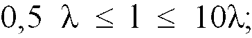
11. A method as claimed in any preceding Claim, characterised in that the wavelength of the transmission is given by the formula
where λ is the wavelength of the transmission through the overburden (34) and s is the distance from the seabed (33) to the reservoir (35).
where λ is the wavelength of the transmission through the overburden (34) and s is the distance from the seabed (33) to the reservoir (35).
12. A method as claimed in any preceding Claim, in which the transmission frequency is
from 0.01 Hz to 1 kHz.
13. A method as claimed in any preceding Claim, characterised in that the transmission frequency is from 1 to 20 Hz.
14. A method as claimed in any of Claims 2 to 10, characterised in that a first transmission is made at a first frequency and received by each receiver in
a tuned array of receivers, then a second transmission is made at a second frequency
and received by the same tuned array of receivers, the receivers being tuned to receive
their respective transmissions.
15. A method as claimed in any preceding Claim, characterised in that it further includes the step of comparing the results of the measurements taken with
the results of a mathematical simulation model based on the known properties of the
reservoir and overburden conditions.
16. A method as claimed in any of Claims 11 to 15, characterised by suppressing the direct wave (41), thereby reducing the required dynamic range of
the receivers (38) and increasing the resolution of the refracted wave (43, 43C).
17. A method of surveying subterranean measures which comprises; performing a seismic
survey to determine the geological structure of a region; and where that survey reveals
the presence of a subterranean reservoir (35), subsequently performing a method as
claimed in any of Claims 1 to 16 to determine the nature of the reservoir (35).
1. Verfahren zum Durchführen einer Untersuchung von unterirdischen Schichten, um nach
einem Kohlenwasserstoff enthaltenden unterirdischen Reservoir (35) zu suchen, oder
um die Natur eines unterseeischen oder unterirdischen Reservoirs (35) zu bestimmen,
dessen annähernde Geometrie und Position bekannt sind, wobei das Verfahren das Anlegen
eines zeitvariablen elektromagnetischen Feldes auf die unterirdischen Schichten, das
Erfassen der Antwort des elektromagnetischen Wellenfeldes, das Suchen eines Bestandteils
in der Antwort des Wellenfeldes, welcher eine gebrochene Welle (43, 43C) darstellt,
und das Bestimmen der Gegenwart und/oder Natur eines beliebigen Reservoirs (35) aufweist,
das auf der Grundlage der Gegenwart oder Abwesenheit eines Bestandteils abgelenkten
Welle (43, 43C) identifiziert wird, wobei das übertragene Feld in der Form einer Welle
vorliegt und wobei der Abstand zwischen dem Sender (37) und einem Empfänger (38) durch
die Formel
wiedergegeben wird, wobei λ die Wellenlänge der Übertragung durch die überlagernde Schicht (34) und l der Abstand zwischen dem Sender (37) und dem Empfänger (38) ist.
wiedergegeben wird, wobei λ die Wellenlänge der Übertragung durch die überlagernde Schicht (34) und l der Abstand zwischen dem Sender (37) und dem Empfänger (38) ist.
2. Verfahren nach Anspruch 1, gekennzeichnet durch den weiteren Schritt, des Analysierens der Auswirkungen auf einen etwaigen erfassten
Bestandteil einer abgelenkten Welle (43C), die durch das Reservoir (35) verursacht wurden, um den Inhalt des Reservoirs (35) auf der Grundlage
der Analyse näher zu bestimmen.
3. Verfahren nach Anspruch 1 oder 2, dadurch gekennzeichnet, dass das angelegte elektromagnetische Feld polarisiert ist.
4. Verfahren nach Anspruch 3, dadurch gekennzeichnet, dass die Polarisierung derart ist, dass der Bestandteil des E-Feldes durch einen horizontalen
Dipol in Richtung zum Empfänger hin geschaffen wird.
5. Verfahren nach einem der vorhergehenden Ansprüche, dadurch gekennzeichnet, dass das Feld unter Verwendung von einem oder mehreren stationären Sendern (37) angelegt
wird.
6. Verfahren nach Anspruch 5, dadurch gekennzeichnet, dass ein stationärer Sender (37) in einem bestehenden Bohrloch angeordnet ist.
7. Verfahren nach einem der vorhergehenden Ansprüche, dadurch gekennzeichnet, dass das Erfassen durch einen oder mehrere stationäre Empfänger (38) erfolgt.
8. Verfahren nach einem der Ansprüche 5 bis 7, dadurch gekennzeichnet, dass der Sender (37) und/oder die Empfänger (38) auf dem oder nahe bei dem Meeresboden
(33) oder dem Boden eines anderen Wassergebiets oder auf der Erdoberfläche angeordnet
sind.
9. Verfahren nach einem der vorhergehenden Ansprüche, dadurch gekennzeichnet, dass das Feld über einen Zeitraum von 3 Sekunden bis 60 Minuten gesendet wird.
10. Verfahren nach Anspruch 9, dadurch gekennzeichnet, dass die Sendezeit von 3 Minuten bis 30 Minuten beträgt.
11. Verfahren nach einem der vorhergehenden Ansprüche, dadurch gekennzeichnet, dass die Wellenlänge der Übertragung durch die Formel

wiedergegeben wird, wobei λ die Wellenlänge der Übertragung durch die überlagernde Schicht (34) und s der Abstand vom Meeresboden (33) zum Reservoir (35) ist.
wiedergegeben wird, wobei λ die Wellenlänge der Übertragung durch die überlagernde Schicht (34) und s der Abstand vom Meeresboden (33) zum Reservoir (35) ist.
12. Verfahren nach einem der vorhergehenden Ansprüche, wobei die Übertragungsfrequenz
von 0,01 Hz bis 1 kHz beträgt.
13. Verfahren nach einem der vorhergehenden Ansprüche, dadurch gekennzeichnet, dass die Übertragungsfrequenz von 1 bis 20 Hz beträgt.
14. Verfahren nach einem der Ansprüche 2 bis 10, dadurch gekennzeichnet, dass eine erste Sendung mit einer ersten Frequenz erfolgt und von jedem Empfänger in einem
abgestimmten Feld von Empfängern empfangen wird, danach eine zweite Sendung mit einer
zweiten Frequenz erfolgt und von demselben abgestimmten Feld von Empfängern empfangen
wird, wobei die Empfänger abgestimmt sind, um ihre entsprechenden Sendungen zu empfangen.
15. Verfahren nach einem der vorhergehenden Ansprüche, dadurch gekennzeichnet, dass das Verfahren ferner den Schritt des Vergleichens der Ergebnisse der erfolgten Messungen
mit den Ergebnissen eines mathematischen Simulationsmodells aufweist, das auf den
bekannten Eigenschaften des Reservoirs und den Bedingungen der überlagernden Schicht
beruht.
16. Verfahren nach einem der Ansprüche 11 bis 15, dadurch gekennzeichnet, dass die direkte Welle (41) unterdrückt wird, wodurch der erforderliche Dynamikbereich
der Empfänger (38) reduziert und die Auflösung der abgelenkten Welle (43, 43C) erhöht
wird.
17. Verfahren zum Untersuchen unterirdischer Messungen, welches das Durchführen einer
seismischen Untersuchung zur Bestimmung der geologischen Struktur einer Region und,
sofern diese Untersuchung das Vorhandensein eines unterirdischen Reservoirs (35) offenbart,
im Anschluss daran die Durchführung eines Verfahrens nach einem der Ansprüche 1 bis
16 aufweist, um die Natur des Reservoirs (35) zu bestimmen.
1. Procédé pour effectuer un relevé de couches souterraines pour rechercher un réservoir
souterrain (35) contenant des hydrocarbures, ou pour déterminer la nature d'un réservoir
souterrain ou sous-marin (35) dont la géométrie et la localisation approximatives
sont connues, qui comprend : le fait d'appliquer un champ électromagnétique variable
dans le temps aux couches souterraines; le fait de détecter la réponse du champ d'onde
électromagnétique; le fait de rechercher, dans la réponse du champ d'onde, une composante
représentant une onde réfractée (43, 43C); et le fait de déterminer la présence et/ou
la nature de tout réservoir (35) identifié, sur base de la présence ou l'absence d'une
composante d'onde réfractée (43, 43C); dans lequel le champ transmis est dans la forme
d'une onde, et dans lequel la distance entre l'émetteur (37) et un récepteur (38)
est donnée par la formule
où λ est la longueur d'onde de l'émission au travers du terrain de couverture et l est la distance entre l'émetteur (37) et le récepteur (38).
où λ est la longueur d'onde de l'émission au travers du terrain de couverture et l est la distance entre l'émetteur (37) et le récepteur (38).
2. Procédé selon la revendication 1, caractérisé par l'étape supplémentaire d'analyser les effets sur toute composante d'onde réfractée
détectée (43C), qui sont dus au réservoir (35), pour déterminer en outre le contenu
du réservoir (35) sur base de l'analyse.
3. Procédé selon la revendication 1 ou la revendication 2, caractérisé en ce que le champ électromagnétique appliqué est polarisé.
4. Procédé selon la revendication 3, caractérisé en ce que la polarisation est telle que la composante de champ électrique est créée par un
dipôle horizontal dans la direction vers le récepteur.
5. Procédé selon une quelconque des revendications précédentes, caractérisé en ce que le champ est appliqué en utilisant un ou plusieurs émetteurs stationnaires (37).
6. Procédé selon la revendication 5, caractérisé en ce qu'un émetteur stationnaire (37) est situé dans un puits existant.
7. Procédé selon l'une quelconque des revendications précédentes, caractérisé en ce que la détection est effectuée par un ou plusieurs récepteurs stationnaires (38).
8. Procédé selon l'une quelconque des revendications 5 à 7, caractérisé en ce que l'émetteur (37) et/ou les récepteurs (38) sont situés sur ou proches du fond de la
mer (33) ou du fond d'une autre zone d'eau, ou sur la surface de la terre.
9. Procédé selon l'une quelconque des revendications précédentes, caractérisé en ce que le champ est émis pendant une durée de 3 secondes à 60 minutes.
10. Procédé selon la revendication 9, caractérisé en ce que la durée d'émission est de 3 minutes à 30 minutes.
11. Procédé selon l'une quelconque des revendications précédentes, caractérisé en ce que la longueur d'onde de l'émission est donnée par la formule
où λ est la longueur d'onde de l'émission au travers du terrain de couverture (34) et s est la distance du fond de la mer (33) au réservoir (35).
où λ est la longueur d'onde de l'émission au travers du terrain de couverture (34) et s est la distance du fond de la mer (33) au réservoir (35).
12. Procédé selon l'une quelconque des revendications précédentes, dans lequel la fréquence
d'émission est de 0,01 Hz à 1 kHz.
13. Procédé selon l'une quelconque des revendications précédentes, dans lequel la fréquence
d'émission est de 1 à 20 Hz.
14. Procédé selon l'une quelconque des revendications 2 à 10, caractérisé en ce que la première émission est faite à une première fréquence et reçue par chaque récepteur
dans une matrice de récepteurs accordés, puis une seconde émission est faite à une
seconde fréquence et reçue par la même matrice de récepteurs accordés, les récepteurs
étant accordés pour recevoir leurs émissions respectives.
15. Procédé selon l'une quelconque des revendications précédentes, caractérisé en ce qu'il comprend en outre l'étape de comparer les résultats des mesures faites avec les
résultats d'un modèle mathématique de simulation basé sur les propriétés connues du
réservoir et l'état du terrain de couverture.
16. Procédé selon l'une quelconque des revendications 11 à 15, caractérisé par la suppression de l'onde directe (41), réduisant de ce fait la gamme dynamique nécessaire
des récepteurs (38) et augmentant la résolution de l'onde réfractée (43, 43C).
17. Procédé pour relever des mesures souterraines qui comprend le fait de réaliser un
relevé sismique pour déterminer la structure géologique d'une région; et, où ce relevé
révèle la présence d'un réservoir souterrain (35), effectuer de façon subséquente
un procédé selon une quelconque des revendications 1 à 16 pour déterminer la nature
du réservoir (35).