| (19) |
 |
|
(11) |
EP 1 272 990 B1 |
| (12) |
EUROPEAN PATENT SPECIFICATION |
| (45) |
Mention of the grant of the patent: |
|
09.06.2004 Bulletin 2004/24 |
| (22) |
Date of filing: 10.04.2001 |
|
| (51) |
International Patent Classification (IPC)7: G08B 5/38 |
| (86) |
International application number: |
|
PCT/IB2001/000592 |
| (87) |
International publication number: |
|
WO 2001/078026 (18.10.2001 Gazette 2001/42) |
|
| (54) |
SECURITY DEVICE WITH BIDIRECTIONAL COMMUNICATION
SICHERHEITSVORRICHTUNG MIT ZWEIRICHTUNGSÜBERWACHUNG
DISPOSITIF DE SECURITE A COMMUNICATION BIDIRECTIONNELLE
|
| (84) |
Designated Contracting States: |
|
AT BE CH CY DE DK ES FI FR GB GR IE IT LI LU MC NL PT SE TR |
| (30) |
Priority: |
11.04.2000 IT PD000084
|
| (43) |
Date of publication of application: |
|
08.01.2003 Bulletin 2003/02 |
| (73) |
Proprietor: System Sensor Division Of Pittway Corporation |
|
St. Charles, IL 60174 (US) |
|
| (72) |
Inventor: |
|
- ZAMBON, Cristiano
I-34100 Trieste (IT)
|
| (74) |
Representative: Modiano, Guido, Dr.-Ing. et al |
|
Modiano & Associati SpA
Via Meravigli, 16
20123 Milano
20123 Milano (IT) |
| (56) |
References cited: :
EP-A- 0 974 947
DE-A- 19 754 222
FR-A- 2 672 145
|
DE-A- 19 744 210
FR-A- 2 643 210
|
|
| |
|
|
|
|
| |
|
| Note: Within nine months from the publication of the mention of the grant of the European
patent, any person may give notice to the European Patent Office of opposition to
the European patent
granted. Notice of opposition shall be filed in a written reasoned statement. It shall
not be deemed to
have been filed until the opposition fee has been paid. (Art. 99(1) European Patent
Convention).
|
TECHNICAL FIELD
[0001] The present invention relates to a security device with bidirectional communication.
[0002] More particularly, the invention relates to a security device capable of communicating
both with a control unit and directly with a user.
BACKGROUND ART
[0003] It is known that most currently commercially available security systems generally
have the following operating criterion.
[0004] A control unit manages peripheral units (usually sensors or actuators) by means of
a two-wire line or by means of radio systems.
[0005] More recent security systems in fact allow to address (via hardware or software)
the peripheral units. In this case, the control unit determines whether, according
to the control program, the environmental parameters detected by the sensors correspond
or not to an alarm condition and the control unit therefore activates, if appropriate,
the corresponding alarm procedures, such as visual or acoustic signals or the like.
[0006] Usually, communication between the control units and the peripheral units is entrusted
to proprietary protocols which are compatible with the power supply requirements,
if any, of the sensors and most of all with the requirements of sturdiness and immunity
to noise which are typical of a security system.
[0007] Clearly, the possibility of communication between the control unit and the peripheral
units allows higher flexibility and maintenance capability of the security system
and ultimately gives an added value to the system as a whole.
[0008] However, communication between the control unit and the peripheral units is entrusted
exclusively to a two-wire line, as mentioned, such as for example a bus, or to radio
systems.
[0009] In practice, the only option is to act from the control unit toward the peripheral
units and it is not possible to act directly on said peripheral units, thus bypassing
the control unit.
DISCLOSURE OF THE INVENTION
[0010] The aim of the present invention is to provide a security device with bidirectional
communication capability which allows users to act directly on the peripheral units
in addition to acting on them from the control unit.
[0011] Within this aim, an object of the present invention is to provide a security device
with bidirectional communication capability which allows to use the normal visual
indication device of a peripheral unit for interacting with said peripheral unit.
[0012] Another object of the present invention is to provide a security device with bidirectional
communication capability which allows to interact with a peripheral unit directly
at the site where said peripheral unit is installed.
[0013] Another object of the present invention is to provide a security device with bidirectional
communication capability which is highly reliable, relatively simple to manufacture
and at competitive costs.
[0014] This aim and these and other objects which will become better apparent hereinafter
are achieved by a security device with bidirectional communication capability, comprising
logic control means which are adapted to control at least one LED for indicating the
operating status of a peripheral unit in which said security device is accommodated,
characterized in that it comprises at least one resistor which is connected in parallel
to said at least one LED, for converting into voltage light energy received from said
at least one LED, said LED being connected to means for evaluating said voltage generated
thereby, said means being in turn connected to said logic control means.
BRIEF DESCRIPTION OF THE DRAWINGS
[0015] Further characteristics and advantages of the invention will become better apparent
from the description of preferred but not exclusive embodiments of the device according
to the present invention, illustrated only by way of non-limitative example in the
accompanying drawings, wherein:
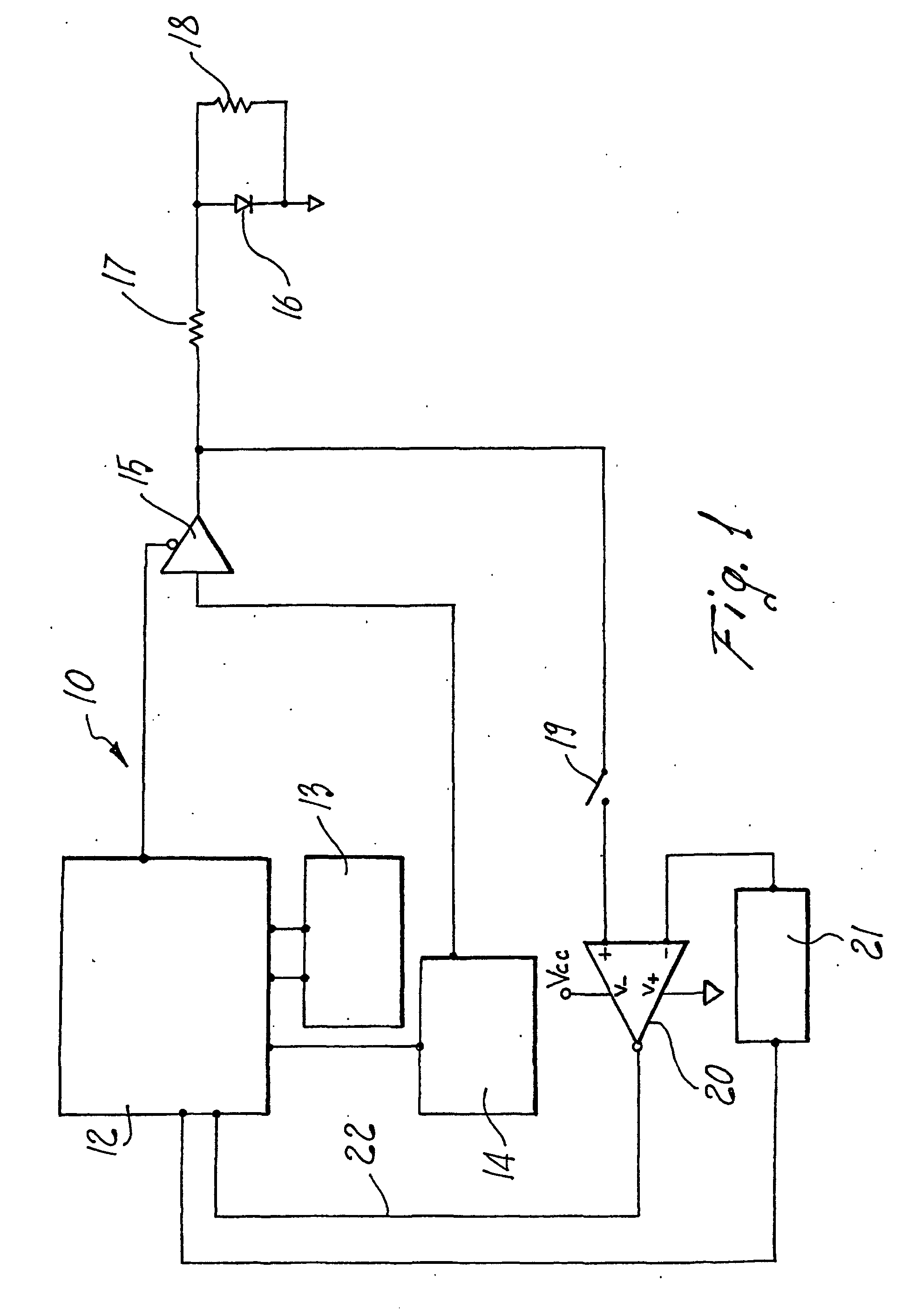
Figure 1 is a circuit diagram of the security device according to the present invention;
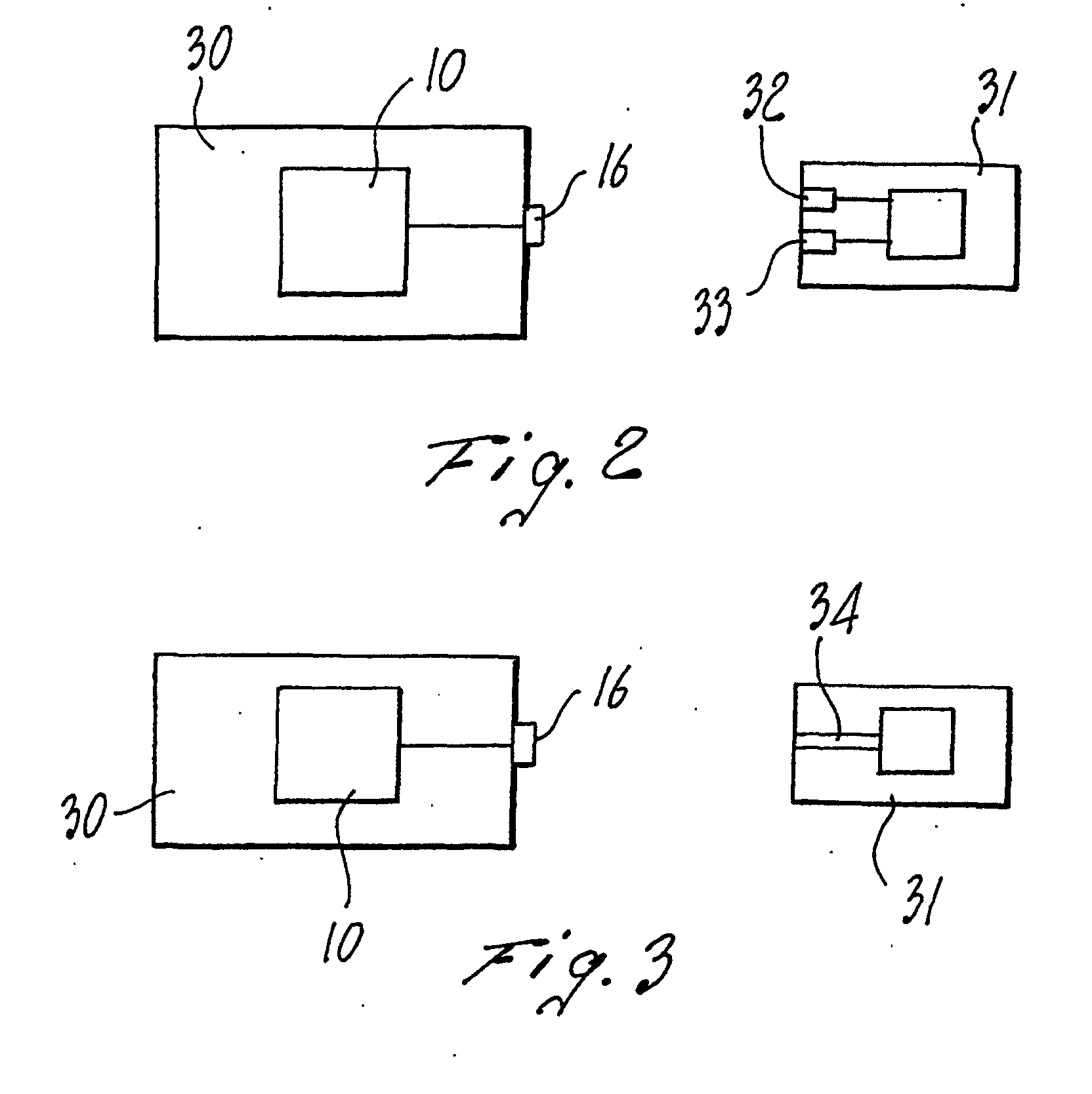
Figure 2 is a block diagram of the interaction between a peripheral unit which accommodates
the security device according to the present invention and an external unit;
Figure 3 is a block diagram of a second embodiment of the interaction between a peripheral
unit in which the device according to the invention is incorporated and an external
unit.
WAYS OF CARRYING OUT THE INVENTION
[0016] With reference to the figures, and initially with reference to Figure 1, the security
device according to the present invention, generally designated by the reference numeral
10, comprises logic control means 12 which are connected to memory means 13 and to
management means 14 which are adapted to manage the operation of at least one LED.
[0017] The logic control means 12 are connected to a power buffer 15, which is adapted to
drive at least one LED 16 which provides an indication of the operating status of
the peripheral unit in which the security device is accommodated.
[0018] The peripheral unit can be for example a sensor or an actuator.
[0019] A resistor 17 is interposed between the output of the power buffer 15 and the LED
16 and allows to reduce the current in output from the power buffer 15 for supplying
power to the LED 16.
[0020] The particularity of the invention is that the LED 16 is used not only as a device
for signaling the operating status of the peripheral unit but also in reverse, as
explained in detail hereinafter.
[0021] The LED is in fact usually a device designed to convert electric energy into light
energy, with a photoelectric effect, in order to provide in this case an indication
of the operating status of the peripheral unit.
[0022] In the device according to the invention, the LED also acts as a photodiode, i.e.,
it performs the opposite conversion, from light energy to electric energy.
[0023] It is in fact known that a p-n junction, if crossed by a current, can emit photons
whose energy is linked to the type of doping of the junction. Likewise, if a p-n junction
is illuminated by photons of the appropriate energy, hole-electron pairs are produced
which, by flowing through the junction, generate a current which is proportional to
the intensity of the incident light.
[0024] Obviously, the efficiency of quantum conversion, i.e., the amount of current that
can be generated in relation to a given incident light energy, is very low for an
LED, since the LED is an optoelectronic device designed and optimized for the opposite
conversion, i.e., from electric energy to light energy.
[0025] However, the photocurrent that is obtained from the LED if it is illuminated appropriately
with a light source tuned to the same wavelength as the LED is capable of providing
a signal whose amplitude is sufficient to allow processing by an amplifier-comparator
block.
[0026] Therefore, by modulating the signal of the illuminating source with a train of pulses,
it is possible to reconstruct said signal at the output of the signal processing system.
[0027] In this manner, an additional semiduplex communication channel is available which,
in addition to the conventional two-wire line that connects the peripheral unit to
a control unit, allows communication with said control unit.
[0028] In practice, the security device 10 according to the invention therefore comprises
an additional resistor 18 which is connected in parallel to the LED 16 so as to convert
into voltage the current generated when the LED 16 acts as a receiver.
[0029] The number of resistors 18 is of course equal to the number of LEDs 16 provided in
output to the peripheral unit that accommodates the security device 10.
[0030] Switching means 19 are further provided in order to connect the voltage signal produced
by the LED 16 when it is lit to comparator means 20 which are adapted to compare said
voltage signal with a comparison voltage 21, so as to generate a signal 22 which represents
the difference between the voltage detected by the LED 16 and the reference voltage
21 sent by the logic control means 12.
[0031] The amplifier-comparator 20 further allows to amplify said voltage difference signal.
[0032] The switching means 19 are therefore normally operatively open when the LED 16 acts
as an optoelectronic device for indicating the operating status of the peripheral
unit, i.e., when it provides an external indication of the operation of said peripheral
unit.
[0033] Vice versa, when the LED 16 acts as a receiving element the switching means 19 are
closed, activating the path that connects the LED 16 to the amplifier-comparator means
20, shifting the power buffer 15 to a high-impedance state.
[0034] Substantially, a second communication channel, this time of the optical type, is
created alongside the normal two-wire or radio communication channel that connects
the peripheral unit to the control unit (which is not shown in the figures).
[0035] Figure 2 is a schematic view of a peripheral unit 30 which internally accommodates
the security device 10 according to the present invention.
[0036] The reference numeral 16 designates, in this case, again the LED for external indication
of the operating status of said peripheral unit.
[0037] In order to illuminate the LED 16 from outside and thus make it act as a receiving
element, a first embodiment provides for an external unit 31 which is appropriately
provided with an optical input and output device.
[0038] In the first embodiment shown in Figure 2, the optical input and output device comprises
at least one ultrabright LED 32 which is arranged to the side of a photodiode or phototransistor
33 so that the LED 32 is capable of illuminating the LED 16 of the peripheral unit
30 and thus make it act as a receiving element.
[0039] At the same time, the photodiode 33 of the external unit 31 allows to receive light
information from the LED 16 of the peripheral unit 30.
[0040] The external unit 31 is appropriately interfaced mechanically with the peripheral
unit 30 so as to keep the optical input and output device 32, 33 at a short distance
from the LED 16.
[0041] In a second embodiment, shown in Figure 3, the peripheral unit 30 is again interfaced
with the external unit 31, but in this case the optical input-output device is constituted
by at least one optical fiber 34.
[0042] This last solution allows the operator to program, test and obtain data from peripheral
units even if they are located in difficult and awkward positions, without having
to remove the peripheral unit from its support.
[0043] In practice it has been observed that the security device according to the invention
allows to obtain an additional bidirectional communication channel which is added
alongside the normal communication channel provided between a peripheral unit and
a control unit meant to control the operation of said peripheral unit.
[0044] Moreover, the "optical" channel thus created allows the operator to act directly
on the peripheral units in the operating environment, i.e., at the installation site,
with consequent advantages in terms of operation and maintenance.
[0045] Moreover, the security device according to the invention can be easily integrated
in a control unit of a commercially known type with a minimal increase in its dimensions.
[0046] The device thus conceived is susceptible of numerous modifications and variations,
all of which are within the scope of the inventive concept; all the details may further
be replaced with other technically equivalent elements.
[0047] In practice, the materials employed, so long as they are compatible with the specific
use, as well as the dimensions, may be any according to requirements and to the state
of the art.
1. A security device with bidirectional communication capability, comprising logic control
means which are adapted to control at least one LED for indicating the operating status
of a peripheral unit in which said security device is accommodated, characterized in that it comprises at least one resistor which is connected in parallel to said at least
one LED, for converting into voltage light energy received from said at least one
LED, said LED being connected to means for evaluating said voltage generated thereby,
said means being in turn connected to said logic control means, said voltage being
indicative of the response of said security device to a signal sent from an external
unit.
2. The device according to claim 1, characterized in that said means for evaluating said voltage generated by said at least one LED comprise
amplifier and comparator means adapted to compare said voltage generated by said LED
with the reference voltage generated by said logic control means, in order to obtain
a voltage difference signal which is adapted to be sent to said logic control means.
3. The device according to claims 1 and 2, characterized in that said amplifier and comparator means are connected to said at least one LED by virtue
of switching means.
4. The device according to one or more of the preceding claims, characterized in that said logic control means drive said at least one LED by means of a power buffer.
5. The device according to one or more of the preceding claims, characterized in that at least one resistor is interposed between said power buffer and said at least one
LED and is connected in series to said at least one LED.
6. The device according to one or more of the preceding claims, characterized in that it comprises an external unit which is adapted to interface with said peripheral
unit that accommodates said security device, said external unit being provided with
an optical input and output device adapted to communicate with said at least one LED.
7. The device according to claim 6, characterized in that said optical input and output device of said external unit comprises at least one
ultrabright LED and at least one photodiode or phototransistor.
8. The device according to claim 6, characterized in that said optical input and output device of said external unit comprises at least one
optical fiber.
9. The device according to one or more of the preceding claims, characterized in that said logic control means are connected to memory means and to means for managing
said at least one LED.
10. An external unit for transmitting an optical signal to an LED of a peripheral unit
provided with a security device according to one or more of the preceding claims,
characterized in that it comprises an optical input and output device which is adapted to communicate bidirectionally
with said at least one LED of said peripheral unit.
11. The external unit according to claim 10, characterized in that said optical input and output device comprises at least one ultrabright LED and at
least one photodiode or phototransistor.
12. The external unit according to claim 10, characterized in that said optical input and output device comprises at least one optical fiber.
13. The external unit according to one or more of claims 10 to 12, characterized in that it is interfaced mechanically with said peripheral unit, so as to keep said optical
input and output device in a position in which it faces said at least one LED of said
peripheral unit.
14. A method for providing an optical communication channel between a security device
of a peripheral unit and an external control unit,
characterized in that it comprises the steps of
using at least one LED of said security device of said peripheral unit to receive
an optical signal sent by said external unit, said LED indicating the operating status
of said peripheral unit;
converting said optical signal received by said at least one LED into a voltage signal,
using a resistor connected in parallel to said at least one LED;
evaluating said voltage signal by way of evaluating means which are connected to logic
control means adapted to control said at least one LED, said method being performed
in the environment where said peripheral unit is installed.
15. The method according to claim 14, characterized in that the step of evaluating said voltage signal comprises the amplification and comparison
of said voltage signal with a reference voltage sent by said logic control means.
16. The method according to claim 14, characterized in that it comprises the step of connecting said at least one LED with means for evaluating
said voltage signal by way of switching means.
1. Sicherheitsvorrichtung mit bidirektionaler Kommunikationsmöglichkeit, welche Logiksteuerungen
umfasst, die so ausgelegt sind, um mindestens eine LED-Funktion für das Anzeigen des
Betriebsstatus einer peripheren Einheit zu steuern, in welcher die Sicherheitsvorrichtung
untergebracht ist;
dadurch gekennzeichnet, dass sie mindestens einen elektrischen Widerstand aufweist, der mit der mindestens einen
LED-Funktion für das Umwandeln in eine Lichtspannungsenergie in Reihe geschaltet ist,
die von der mindestens einen LED-Funktion erhalten wird, wobei die LED-Funktion mit
Vorrichtungen für das Auswerten der dadurch generierten Spannung verbunden ist, und
wobei diese Vorrichtungen wiederum mit Logiksteuerungen verbunden sind, wobei die
generierte Spannung die Antwort der Sicherungsvorrichtung auf ein Signal hin anzeigt,
das von einer Außeneinheit gesendet worden ist.
2. Sicherheitsvorrichtung nach Anspruch 1, dadurch gekennzeichnet, dass eine Vorrichtung für das Auswerten der Spannung, die von mindestens einer LED-Funktion
generiert worden ist, Verstärker- und Komparatoreinrichtungen aufweist, die so ausgelegt
sind, um die von der LED-Funktion generierte Spannung mit der von den Logiksteuerungsvorrichtungen
generierten Referenzspannung zu vergleichen, um dabei ein Spannungsdifferenzsignal
zu erhalten, das zum Senden an die Logiksteuerungsvorrichtungen ausgelegt wird.
3. Sicherheitsvorrichtung nach Anspruch 1 und 2, dadurch gekennzeichnet, dass die Verstärker- und Komparatoreinrichtungen mit mindestens einer LED-Funktion aufgrund
von Schaltmittel verbunden sind.
4. Sicherheitsvorrichtung nach einem oder mehreren der voranstehenden Ansprüche, dadurch gekennzeichnet, dass durch die Logiksteuerungsvorrichtungen mindestens eine LED-Funktion mittels eines
Energiebuffers angetrieben wird.
5. Sicherheitsvorrichtung nach einem oder mehreren der voranstehenden Ansprüche, dadurch gekennzeichnet, dass mindestens ein elektrischer Widerstand zwischen dem Energiebuffer und der mindestens
einen LED-Funktion angeordnet ist, und der mit der zumindest einen LED-Funktion in
Reihe geschaltet ist.
6. Sicherheitsvorrichtung nach einem oder mehreren der voranstehenden Ansprüche, dadurch gekennzeichnet, dass sie eine Außeneinheit umfasst, welche so ausgelegt ist, dass diese mit der peripheren
Einheit mit einer elektronischen Anpassschaltung gekoppelt ist, in welcher die Sicherheitsvorrichtung
untergebracht ist, wobei die Außeneinheit mit einer optischen Eingangs- und Ausgangsvorrichtung
ausgestattet ist, die so ausgelegt ist, um mit mindestens einer LED-Funktion kommunizieren
zu können.
7. Sicherheitsvorrichtung nach Anspruch 6, dadurch gekennzeichnet, dass die optische Eingangs- und Ausgangsvorrichtung der Außeneinheit mindestens eine ultrahelle
Leuchtdiode und mindestens eine Photodiode oder einen Phototransistor aufweist.
8. Sicherheitsvorrichtung nach Anspruch 6, dadurch gekennzeichnet, dass die optische Eingangs- und Ausgangsvorrichtung der Außeneinheit mindestens einen
optischen Lichtwellenleiter aufweist.
9. Sicherheitsvorrichtung nach einem oder mehreren der voranstehenden Ansprüche, dadurch gekennzeichnet, dass die Logiksteuerungsvorrichtungen mit einer Speichereinrichtung und mit Mittel für
das Handhaben von mindestens einer LED-Funktion verbunden sind.
10. Außeneinheit für das Übertragen eines optischen Signals an eine LED-Funktion von einer
peripheren Einheit, in der die Sicherheitsvorrichtung gemäß einem oder mehreren der
voranstehenden Ansprüche bereitgestellt wird, dadurch gekennzeichnet, dass die Außeneinheit eine optische Eingangs- und Ausgangsvorrichtung umfasst, die so
ausgelegt ist, um mit mindestens einer LED-Funktion der peripheren Einheit bidirektional
kommunizieren zu können.
11. Außeneinheit nach Anspruch 10, dadurch gekennzeichnet, dass die optische Eingangs- und Ausgangsvorrichtung mindestens eine ultrahelle Leuchtdiode
und mindestens eine Photodiode oder einen Phototransistor aufweist.
12. Außeneinheit nach Anspruch 10, dadurch gekennzeichnet, dass die optische Eingangs- und Ausgangsvorrichtung mindestens einen optischen Lichtwellenleiter
aufweist.
13. Außeneinheit nach einem oder mehreren der Ansprüche 10 bis 12, dadurch gekennzeichnet, dass diese mit der peripheren Einheit über eine elektronische Anpassschaltung mechanisch
gekoppelt ist, um so die optische Eingangs- und Ausgangsvorrichtung in einer Position
halten zu können, in der sie der mindestens einen LED-Funktion der peripheren Einheit
gegenüberliegt.
14. Verfahren für das Bereitstellen eines optischen Kommunikationskanals zwischen einer
Sicherheitsvorrichtung aus einer peripheren Einheit und einer äußeren Steuereinheit,
dadurch gekennzeichnet, dass es die folgenden Schritte umfasst:
Benutzen von mindestens einer LED-Funktion der Sicherheitsvorrichtung aus der peripheren
Einheit zum Empfang eines optischen Signals, das von der Außeneinheit gesendet worden
ist, wobei die LED-Funktion den Betriebsstatus der peripheren Einheit anzeigt;
Umwandeln des optischen Signals in ein Spannungssignal, das von mindestens einer LED-Funktion
empfangen worden ist, wobei ein elektrischer Widerstand verwendet wird, der mit mindestens
einer LED-Funktion in Reihe geschaltet ist;
Auswerten des Spannungssignals mittels Auswertevorrichtungen, die mit den Logiksteuerungsvorrichtungen
verbunden sind, die so ausgelegt sind, um mindestens eine LED-Funktion steuern zu
können, wobei das Verfahren in der Umgebung ausgeführt wird, in der die periphere
Einheit installiert ist.
15. Verfahren nach Anspruch 14, dadurch gekennzeichnet, dass der Schritt des Auswertens des Spannungssignals das Verstärken und den Vergleich
des Spannungssignals mit einer Referenzspannung aufweist, die von den Logiksteuerungsvorrichtungen
gesendet worden ist.
16. Verfahren nach Anspruch 14, dadurch gekennzeichnet, dass es den Schritt des Verbindens von mindestens einer LED-Funktion mit Vorrichtungen
für das Auswerten des Spannungssignals über Schaltmittel umfasst.
1. Dispositif de sécurité permettant une communication bidirectionnelle, comprenant des
moyens de commande logiques aptes à commander au moins une DEL pour indiquer l'état
de fonctionnement d'un périphérique dans lequel est logé ledit dispositif de sécurité,
caractérisé en ce qu'il comprend au moins une résistance montée en parallèle avec ladite au moins une DEL,
pour convertir en tension l'énergie lumineuse reçue de ladite au moins une DEL, ladite
DEL étant connectée à un moyen pour évaluer ladite tension générée par celle-ci, ledit
moyen étant lui-même connecté auxdits moyens de commande logiques, ladite tension
indiquant la réponse dudit dispositif de sécurité à un signal envoyé depuis un système
extérieur.
2. Dispositif selon la revendication 1, caractérisé en ce que ledit moyen pour évaluer ladite tension générée par ladite au moins une DEL comporte
un amplificateur et un comparateur aptes à comparer ladite tension générée par ladite
DEL avec la tension de référence générée par lesdits moyens de commande logiques,
afin d'obtenir un signal de différence de tension apte à être envoyé auxdits moyens
de commande logiques.
3. Dispositif selon les revendications 1 et 2, caractérisé en ce que ledit amplificateur et ledit comparateur sont connectés à ladite au moins une DEL
par l'intermédiaire de moyens de commutation.
4. Dispositif selon une ou plusieurs des revendications précédentes, caractérisé en ce que lesdits moyens de commande logiques excitent ladite au moins une DEL par l'intermédiaire
d'un organe de puissance.
5. Dispositif selon une ou plusieurs des revendications précédentes, caractérisé en ce qu'au moins une résistance est intercalée entre ledit tampon de puissance et ladite au
moins une DEL et est montée en série avec ladite au moins une DEL.
6. Dispositif selon une ou plusieurs des revendications précédentes, caractérisé en ce qu'il comprend un système extérieur apte à assurer la liaison avec ledit périphérique
qui contient ledit dispositif de sécurité, ledit système extérieur étant pourvu d'un
dispositif optique d'entrée et de sortie apte à communiquer avec ladite au moins une
DEL.
7. Dispositif selon la revendication 6, caractérisé en ce que ledit dispositif optique d'entrée et de sortie dudit système extérieur comporte au
moins une DEL ultralumineuse et au moins une photodiode ou un phototransistor.
8. Dispositif selon la revendication 6, caractérisé en ce que ledit dispositif optique d'entrée et de sortie dudit système extérieur comporte au
moins une fibre optique.
9. Dispositif selon une ou plusieurs des revendications précédentes, caractérisé en ce que lesdits moyens de commande logiques sont connectés à une mémoire et à un moyen pour
gérer ladite au moins une DEL.
10. Système extérieur pour transmettre un signal optique à une DEL d'un périphérique pourvu
d'un dispositif de sécurité selon une ou plusieurs des revendications précédentes,
caractérisé en ce qu'il comporte un dispositif optique d'entrée et de sortie apte à communiquer de manière
bidirectionnelle avec ladite au moins une DEL dudit périphérique.
11. Système extérieur selon la revendication 10, caractérisé en ce que ledit dispositif optique d'entrée et de sortie comporte au moins une DEL ultralumineuse
et au moins une photodiode ou un phototransistor.
12. Système extérieur selon la revendication 10, caractérisé en ce que ledit dispositif optique d'entrée et de sortie comporte au moins une fibre optique.
13. Système extérieur selon une ou plusieurs des revendications 10 à 12, caractérisé en ce qu'il est mis mécaniquement en liaison avec ledit périphérique de manière à maintenir
ledit dispositif optique d'entrée et de sortie dans une position dans laquelle il
est en regard de ladite au moins une DEL dudit périphérique.
14. Procédé pour réaliser un canal de communication optique entre un dispositif de sécurité
d'un périphérique et un système de commande extérieur, caractérisé en ce qu'il comprend les étapes consistant à
utiliser au moins une DEL dudit dispositif de sécurité dudit périphérique pour
recevoir un signal optique envoyé par ledit système extérieur, ladite DEL indiquant
l'état de fonctionnement dudit périphérique ;
convertir ledit signal optique reçu par ladite au moins une DEL en signal de tension,
à l'aide d'une résistance montée en parallèle avec ladite au moins une DEL ;
évaluer ledit signal de tension à l'aide d'un moyen d'évaluation qui est connecté
à des moyens de commande logiques aptes à commander ladite au moins une DEL, ledit
procédé étant mis en oeuvre dans l'environnement où est installé ledit périphérique.
15. Procédé selon la revendication 14, caractérisé en ce que l'étape d'évaluation dudit signal de tension comporte l'amplification et la comparaison
dudit signal de tension avec une tension de référence envoyée par lesdits moyens de
commande logiques ;
16. Procédé selon la revendication 14, caractérisé en ce qu'il comporte l'étape consistant à connecter ladite au moins une DEL avec un moyen pour
évaluer ledit signal de tension par l'intermédiaire d'un moyen de commutation.