(57) To make simple in structure and to still ensure precise disc loading, a disc loading-and-unloading
structure for a disc apparatus comprises a drive motor (37), a drive roll assembly
(8), a free-roll slider (14), a rotary lever (26), a slider (30), and link-and-spring
connection means (19, 20, 22 and 25). The drive roll assembly has first and second
drive rolls (5 and 9), an intervening transmission gear wheel (12), and a rotatable
arm plate (8a). The first drive roll (5) is rotatably fixed to a stationary stud axle
(7) next to one end of the disc slot (4), and is connected to the drive motor. The
first and second drive rolls are fixed to the opposite ends of the rotatable arm plate
(8a) with the intervening transmission gear wheel (12) sandwiched therebetween. The
free-roll slider (14) is next to the other end of the disc slot. The free-roll slider
has first and second free rolls (13 and 15), and a slidable arm plate (14a), and the
first and second free rolls are fixed to the opposite ends of the slidable arm plate
(14a). The rotary lever (26) lies on the rear side of the chassis (6) so that its
free end (27) may abut on the disc when advancing toward the final rear position.
The slider (30) is operatively connected to the rotary lever (26). The link-and-spring
connection means normally urges the free-roll slider toward the drive roll assembly,
allowing the free-roll slider to move apart from the drive roll assembly as a counter
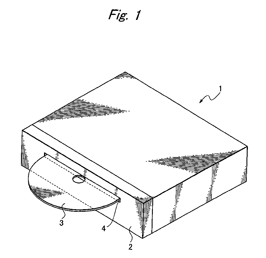
action to the hitting-and-pushing by a disc when inserted from the disc slot (Fig.
1).
|
|
