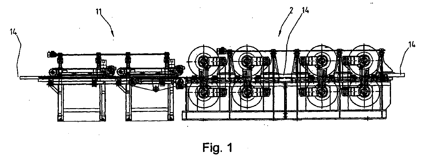
(57) Machine for front joining and sticking of oblong wood workpieces by toothed front
joints and referential procedure consists of the flow press (2) or entrance conveying
line (1), and solves the problem of simple and quality front joining and sticking
of workpieces (14), which travel through them fast and fluently in a consecutive row,
irrespective of possible yet allowed curvature and dimensional deviation. This is
enabled by the construction of entrance conveyors (3) and exit conveyors (4) of the
conveying line (1), equipped with mechanisms (8) for adjustment of side chain units
(6,7), and with elastic couplings (28), whereby inside the side chain units (7 and/or
6) the elastic insertions (20) are placed, and inside pressing conveyors (9) the elastic
insertions (77) are placed. Joints among individual entrance conveyors (3), among
individual exit conveyors (4), and among conveyors (3,4) are likewise elastic constructions
by means of adjustable screws (53,56) placed between fixed cantilevers (51 or 54),
and between tension cantilevers (52,55). It is further enabled by the construction
of entrance units (84) and exit units (85) in the flow press (2), or by the construction
of pushing wheel pairs (98,99) inside them, and which are simultaneously driven by
the central driving coupling (86). For this purpose, each wheel pair (100,101 and
102,103) is equipped with a pair of flexible cranks (106,107 or 110,111), the cylinder
(104) for pressure adjustment, the cylinder (105) for position adjustment, the mechanism
(112) for interactive distance adjustment. Pushing wheel pairs (98) also have the
cylinder (121) for the horizontal shift regulation and the shift-meter (122) with
which the force meter (123) is connected, and which is placed at the end of the last
pushing wheel pair (99).
|
|
