| (19) |
 |
|
(11) |
EP 1 112 036 B1 |
| (12) |
EUROPEAN PATENT SPECIFICATION |
| (45) |
Mention of the grant of the patent: |
|
08.12.2004 Bulletin 2004/50 |
| (22) |
Date of filing: 08.09.1999 |
|
| (51) |
International Patent Classification (IPC)7: A61C 5/10 |
| (86) |
International application number: |
|
PCT/SE1999/001559 |
| (87) |
International publication number: |
|
WO 2000/015137 (23.03.2000 Gazette 2000/12) |
|
| (54) |
METHOD FOR THE PRODUCTION OF A DENTAL PRODUCT OR OTHER PRODUCT FOR THE HUMAN BODY
AND PRODUCT
VERFAHREN ZUR HERSTELLUNG EINES DENTALPRODUKTES UND PRODUKT
PROCEDE POUR LA PRODUCTION D'UN PRODUIT DENTAIRE OU D'UN AUTRE PRODUIT A USAGE HUMAIN
ET PRODUIT
|
| (84) |
Designated Contracting States: |
|
AT BE CH CY DE DK ES FI FR GB GR IE IT LI LU MC NL PT SE |
| (30) |
Priority: |
11.09.1998 SE 9803075
|
| (43) |
Date of publication of application: |
|
04.07.2001 Bulletin 2001/27 |
| (73) |
Proprietor: Nobel Biocare AB (publ) |
|
402 26 Göteborg (SE) |
|
| (72) |
Inventors: |
|
- ANDERSSON, Matts
S-443 39 Lerum (SE)
- CARLSTRÖM, Elis
S-418 71 Göteborg (SE)
- ERIKSSON, Mikael
S-414 70 Göteborg (SE)
|
| (74) |
Representative: Olsson, Gunnar |
|
Nobel Biocare AB (publ),
Box 5190
402 26 Göteborg
402 26 Göteborg (SE) |
| (56) |
References cited: :
EP-A1- 0 384 907
EP-A2- 0 384 908
|
EP-A1- 0 389 461
|
|
| |
|
|
|
|
| |
|
| Note: Within nine months from the publication of the mention of the grant of the European
patent, any person may give notice to the European Patent Office of opposition to
the European patent
granted. Notice of opposition shall be filed in a written reasoned statement. It shall
not be deemed to
have been filed until the opposition fee has been paid. (Art. 99(1) European Patent
Convention).
|
TECHNICAL FIELD
[0001] The present invention relates to a method for producing a dental product or other
product for the human body using material in powder form. In a first manufacturing
stage, with the aid of a mould tool, the product is given a shape which is larger
than its final shape, and in further manufacturing stages the product is subjected
to working and material shrinkage/sintering to obtain the final shape. The invention
also relates to a product intended as a component in a dental application or other
application in the human body, where it cooperates with members in the form of implants,
attachment parts for implants, bones, for example dentine, tooth remnants, etc. The
product is made up from worked and sintered and worked powder material.
PRIOR ART
[0002] It is already known to make products or bodies of the type in question using powder
material in the form of ceramic powder. In this context, it is known to use mould
tools in which the ceramic powder is applied. The mould tool is given a larger shape
or size. The ceramic powder is applied in the mould and is exposed to compression
forces, after which the compressed body is worked and shrunk further in a sintering
process.
[0003] Reference may be made in entirely general terms to manufacturing principles which
are proposed and used in the Procera technique for manufacturing products of the type
in question and where, inter alia, final outer shapes are produced from enlarged outer
shapes.
[0004] Thus, from United States Patent 5,192,173 (with the same inventor) it is already
known to create a linearly enlarged shape on the tool in question. Reference is also
made to European Patent 384,908 B1 (same inventor) which shows that a linearly enlarged
body can be subjected to a sintering process so as to be given its desired final shape.
[0005] It is also known to make products or bodies of the abovementioned type from metal.
The outer shape of the product is in this case turned or milled from a blank. An electro-oxidation
tool with an outer shape corresponding to the inner shape of the product is made and
is used for producing the inner surface of the product by means of electro-oxidation.
DISCLOSURE OF THE INVENTION
TECHNICAL PROBLEM
[0006] The production of ceramic products and metal products has hitherto had to be carried
out using two completely different techniques which have been employed within the
technical area of dental technology and technology related to the human body. This
has divided resources for manufacturers of these types of products and other products
for the human body. There is a requirement for the technical resources to be brought
together more effectively and, for example, for the same types of personnel to be
used to produce caps, spacers, bridges, etc. The invention aims to solve this problem
among others.
[0007] In the sector concerned with the manufacture of products, for example caps, made
of metal material, consideration has been given to imitating the principles used for
ceramic caps or equivalent. However, there has been strong technical opposition and
considerable bias against its being possible, in serial manufacture of structurally
robust caps/products which are to function in a technically severe environment (in
the patient's mouth) and therefore must have strict strength requirements and at the
same time upholding the precision requirements, to be able to manufacture caps/products
in the same way as in ceramic production.
[0008] The invention counters this strong technical opposition and bias and takes a completely
new approach in order to permit a new type of manufacture of caps/products of the
type in question.
[0009] There is a need to technically simplify, and to make less expensive, the previous
manufacture of caps and other dental products using mechanical working and electro-oxidation.
The invention solves this problem too and now proposes principles in which previous
strength and precision requirements (0.2 µm) can also be maintained.
[0010] In connection with the new principles for production of caps/products made of metal,
there is a need to be able to vary the strength requirements, precision requirements,
manufacturing process, etc. The invention solves this set of problems too and is not
confined to individual procedures for achieving the requirements set. The new principles
are especially suited to titanium powder which has the best biocompatible character.
However, there have been strong doubts as to whether it is in principle possible to
make caps and similar products from titanium powder material.
SOLUTION
[0011] The feature which can principally be regarded as characterizing a method according
to the invention is that metal powder is applied to the mould tool, and that the mould
tool with the applied metal powder is placed in pressure-generating equipment where
the powder applied to the mould tool is subjected to compaction pressure which compacts
the powder so that at least an 80 percent basic density is obtained in the material,
and that thereafter the material compacted on the mould tool is first machined and
then removed from the mould tool, after which the said material shrinkage/sintering
stages are carried out so that the final shape is obtained, and at the same time a
porosity of at most about 6 percent by volume, preferably at most 2 to 3 percent by
volume, is obtained in the sintered product.
[0012] In one embodiment, the outer shape of the product is produced or worked (in an enlarged
state), after which the product's final shape is obtained in the sintering process.
The product is given a distinct or substantial homogeneity with respect to the distribution
of the porosity. The material of the product is treated in such a way by the new method
that it becomes ductile (substantially ductile) so that there is no tendency to crack
or fracture under the effect of force.
[0013] In one proposed embodiment, the powder, on application to the mould tool in question,
or stamp, is arranged in a powder-receiving unit in which the outer shape of the stamp
can be lowered so that the powder surrounds the outer surface of the stamp. The powder
can in this case be poured or applied into a tube-like or rubber bladder-like powder-receiving
unit with elastic wall, which for example can be a silicone wall, via which the pressure
is allowed to act in the pressure-generating equipment. The powder material chosen
is preferably titanium powder which can comprise powder of the type TWC-f, whose particles
are deformed by the compaction or the action of pressure in the pressure-generating
equipment. The de-moulding of the compacted metal powder from the mould tool or stamp
is preferably done in a bath of liquid nitrogen/air, and the stamp and the metal powder
are in this case chosen with different coefficients of expansion, which means that
the de-moulding is made considerably simpler. The sintering process in carried out
in a vacuum sintering appliance.
[0014] In one embodiment, a number of mould tools or stamps which represent a number of
possible unique or individual inner shapes of the product are produced. The respective
stamp is selected from a selection of stamps depending on the inner shape which the
product is to be given.
[0015] The metal powder material compacted on the mould tool or stamp is machined by turning
or milling, the mould tool/stamp being arranged together with the compacted material.
The product can in this case be given a shape with a cap-like character where the
inner shape of the product corresponds to the outer surface of the mould tool/stamp,
and the outer shape of the product is machined, for example by turning or milling.
The turning or milling is preferably carried out from the upper part of the cap-like
product and working downwards.
[0016] The mould tool/stamp is designed with a degree of enlargement which is preferably
chosen within the range of enlargement immediately over 0% and up to about 12%, or
immediately below 12%. The compaction pressure is chosen within the range of 300 to
900 MPa. The degree of enlargement used within the said range can be determined as
a function of the compaction pressure used. The shrinkage or sintering operation provides
a shrinkage or sintering which is slightly below the chosen degree of enlargement.
The product is produced with inner or outer shapes produced with a degree of precision
of about 20 µm. The product is preferably a thin-walled product, with values within
the range of 400 to 600 µm. The product or the cap can also be produced with a precision
which provides play of 100 to 400 µm in relation to the opposing surface of the dental
member in question or the dental component in question.
[0017] Titanium powder is preferably used, but it is possible per se alternatively to use
gold alloy or steel powder material.
[0018] The new product can principally be regarded as being characterized by the fact that
the powder material consists of or comprises metal powder material deformed by compaction
and sintered and having a porosity of at most 6, preferably 2 to 3, percent by volume.
[0019] The product is preferably (substantially) ductile and is (substantially) homogeneous
and with evenly distributed porosity.
[0020] In a preferred embodiment, the product has essentially the shape of a cap. The product
is thin-walled and can have a wall thickness or wall thicknesses within the range
of 400 to 600 µm. The product has a precision fit on its inner and/or outer shapes
of about 20 µm. The product or the cap forms a self-supporting structure or construction
whose strength properties correspond to those of a conventional product for the dental
application or other application in the human body. The product or the cap preferably
has a degree of compaction which allows it to be worked by cutting tools, for example
turning or milling, when producing the outer shape. The product consists or is made
of titanium powder material in the first instance, although gold alloy or steel powder
can alternatively be used.
ADVANTAGES
[0021] A surprising effect is that the strict precision requirements in accordance with
the present case can be obtained with such a considerable degree of sintering of the
metal powder, especially titanium powder, in question here.
[0022] The features which have been proposed above permit a considerably simplified manufacture
of metal caps and products for dental application. Conventional press moulding and
de-moulding principles as well as sintering principles can be used, so that technically
simple and well - proven operations are possible. Tests carried out with respect to
strength and precision show surprising effects in that the cap/product can be made
at least as strong and accurately as caps/products produced using conventional techniques
and by conventional methods. In addition, it is possible to control the manufacturing
process so that discoloring of the product's surface(s) is eliminated. Particular
advantages of the invention are obtained when titanium powder is used. Titanium powder
can give strong, load-bearing products or caps.
DESCRIPTION OF THE FIGURES
[0023] A presently proposed embodiment of a method, device and use of the invention will
be described below with reference to the attached drawings, in which
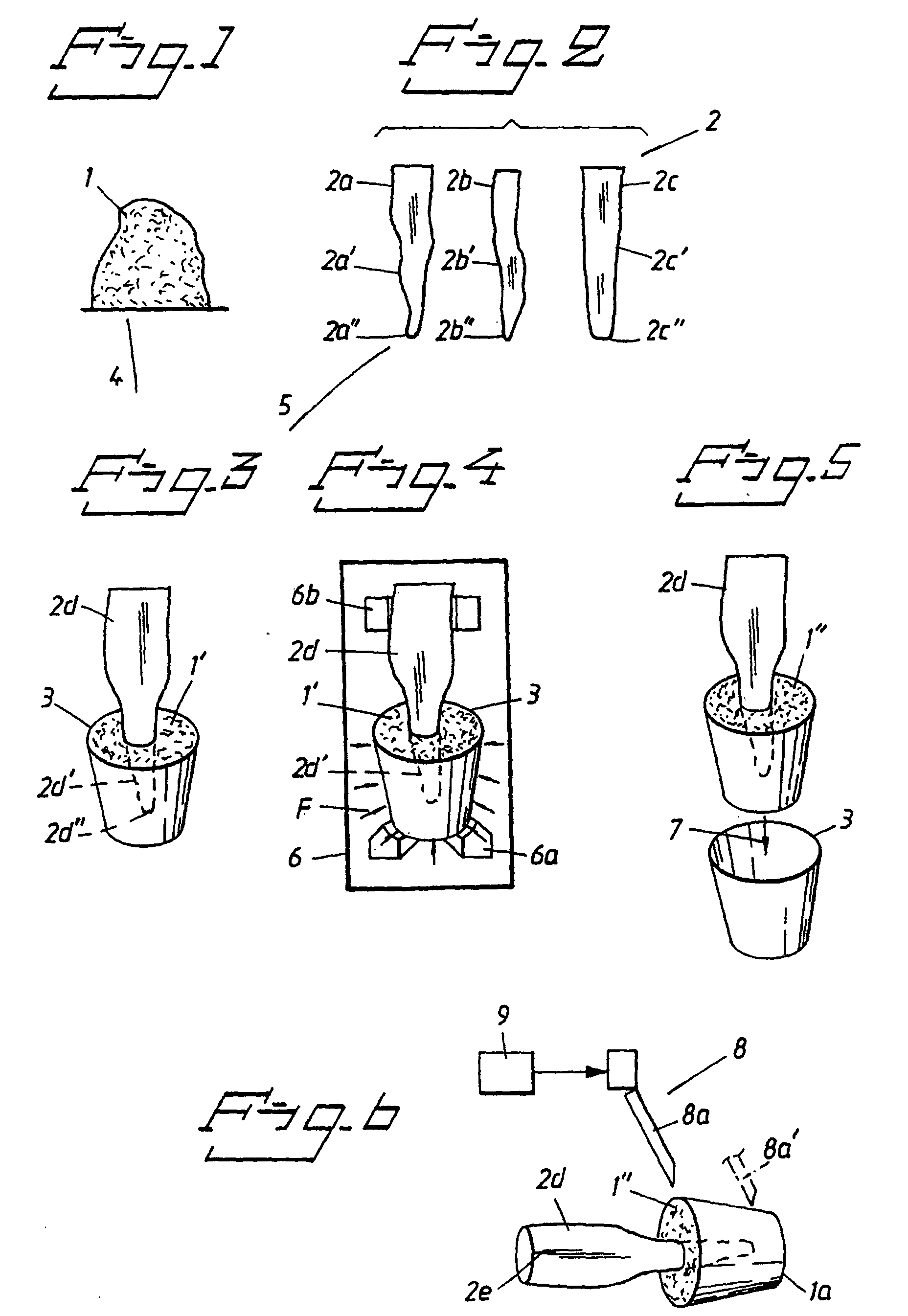
Figure 1 is a diagrammatic representation of the titanium powder used,
Figure 2 shows side views of parts of stamps which are included in a selection of
stamps or tools,
Figure 3 shows in a perspective view, obliquely from above, a stamp chosen from the
selection according to Figure 2 and applied in powder according to Figure 1, which
powder is applied in a tube-shaped container,
Figure 4 is a perspective and diagrammatic representation of the components according
to Figure 3 introduced into compaction equipment,
Figure 5 is a perspective view of compacted powder adhering to the stamp in question,
removed from the equipment according to Figure 4, the container according to Figure
3 being separated from the stamp and the compacted powder,
Figure 6 is a diagrammatic representation of the powder body and the stamp alongside
or in machining equipment which is intended to give the metal powder body its outer
shape,
Figure 7 is a diagrammatic side view showing the de-moulding function for the stamp
and the worked powder body,
Figure 8 is a diagrammatic side view showing the worked powder body placed in a sintering
oven,
Figure 9 shows, in a side view, an example of a structural design of a product/cap,
Figures 10, 11 and 12 show, in different perspectives, three different caps produced
according to the new method.
DETAILED EMBODIMENT
[0024] Figure 1 shows diagrammatically a metal powder 1 which in the present case is a titanium
powder, for example of the type TWC-f (Teledyn Wah Chang, where f stands for "fine")
HDH 270 Mesh with a particle size of 53 µm. The powder is a so-called coarse powder
(not granular).
[0025] Figure 2 shows symbolically and partially a selection of mould tools 2, which are
three in number and have been designated 2a, 2b, 2c. It is possible to have more stamps
in the selection. Each stamp has a unique or individual outer shape 2a', 2b', 2c'.
The surface of each stamp tapers towards the free end 2a", 2b", 2c" of the stamp.
[0026] Figure 3 shows a stamp 2d chosen from the selection 2 and having the same character
as the other stamps, the outer surface having been designated by 2d' and the tip by
2d". Figure 3 shows an elastic container 3 which has the shape of a tube-like unit
or bladder which, in this example, is made of silicone. The container or bladder can
be filled with powder 1' and the stamp 2d lowered into the powder (and/or the bladder
with the powder can be pushed onto the stamp) with its said outer shape 2d', which
is entirely surrounded by the powder. The transfer of the powder has been symbolized
by 4 and the transfer of the stamp by 5 (Figures 1 and 2, respectively).
[0027] The stamp 2d and container 3 with powder 1' have been transferred to a heating oven
6 according to Figure 4. The combination of 2d and 3 is supported in the oven by support
members 6, 6b. The oven is of a type known per se and can be a so-called ISOSTAT press
which is sold commercially. It is possible per se to use a special press which gives
high pressures. The pressure in the press can in one embodiment vary from 300 MPa
and upwards, for example to 900 MPa or more, and in each case a working pressure is
assumed which is to be used for the product in question. As an example, the work pressure
has been chosen at 320 MPa. The pressure used means that the powder 1' in the container
3 is pressed against the outer surface 2d' of the tool or stamp by virtue of the elastic
wall of the container 3, the press forces being indicated by arrows F in Figure 4.
The pressure can alternatively be exerted in one, two or more cycles. The pressure
can be successively increased over a certain period of time. The pressure can be allowed
to act on the powder for a predetermined period of time, for example 15 minutes. The
pressure means that the powder is compacted to form a powder body in which powder
particles or corresponding units are compacted in such a way that the particles or
units are deformed. The powder body is pressed with great force against the outer
surface 2d' of the stamp and comes to form a common unit with the stamp. The combination
of 1', 2d and 3 can in turn be enclosed in a rubber covering (not shown) in order
for the powder to be held in place. The covering can be a rubber balloon. The pressure
treatment or compaction of the powder body means that it is possible to choose a basic
density of the powder material of between about 80% and about 90%, or a porosity of
between about 10 and 20 percent by volume.
[0028] According to Figure 5, the compacted powder body 1" with attached stamp and container
(or balloon) 3 is removed from the oven 6. The container 3 or remains thereof (the
balloon) are removed from the powder body in the direction of arrow 7.
[0029] Figure 6 shows a machining stage for producing and/or treating the outer shape of
the powder body 1". The machining equipment can be a turning lathe, milling device,
etc., and has been symbolized by 8. The lathe bit or milling head 8a, 8a' has been
shown in two positions. The machining preferably starts at the free/outer end 1a of
the powder body and works downwards/inwards. This is done in order to achieve the
best possible function and, for example, to prevent the cap from coming loose due
to shiny and smooth surfaces in cooperation during machining. The particle size of
the material of the stamp and cap can be included as parameters in the machining.
The outer shape formed on the powder body 1' is controlled from a control function
9 which controls the machining equipment 8. The control function is already well known
and will therefore not be described in detail here. Sharp edges and corners can also
be milled or turned. Cooling agents, for example Medicway M15, are used during machining
in order to prevent unwanted effects (discoloring) on the material in dry-milling
or dry-turning.
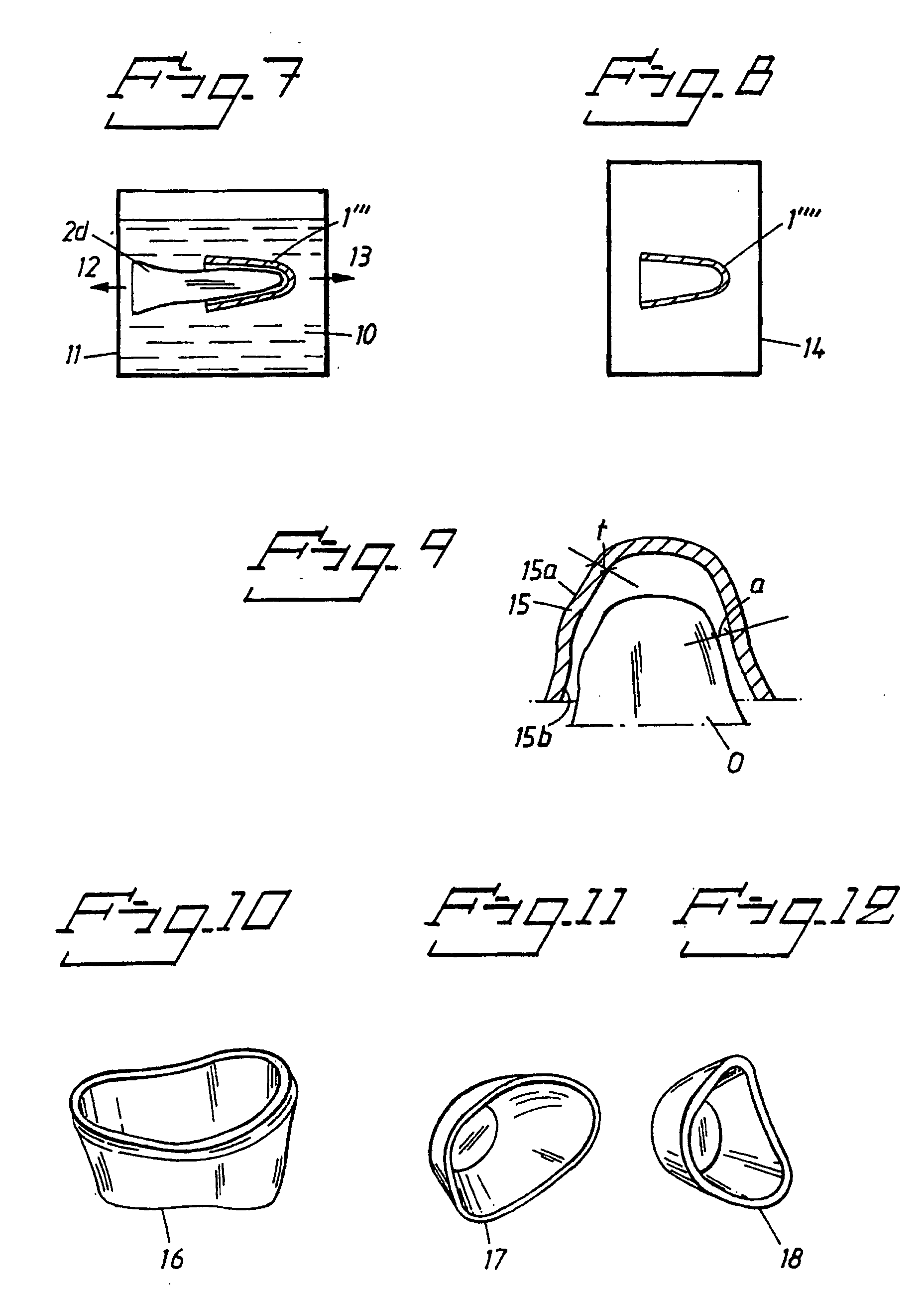
[0030] Figure 7 shows the de-moulding function for the product 1"' which has been made and
which, in the present case, has the form of a cap. In a preferred embodiment, the
de-moulding is carried out using liquid nitrogen/air 10 in a container 11. The nitrogen/air
is at a temperature of about -180°C. The stamp or tool 2d is in the present case made
of material with a higher coefficient of expansion than the titanium/powder body.
In this example, pure aluminium is chosen for the stamp/tool having a coefficient
of expansion of 25 x 10
-6°C
-1. The titanium has a coefficient of expansion of 8.5 x 10
-6°C
-1. This therefore means that the stamp 2d shrinks more than the powder body 1"' and
that simple separation can take place. The separation function is symbolized by arrows
12, 13.
[0031] Figure 8 shows the shrinkage or sintering function for the enlarged shape 1"' for
the product's final shape. The cap 1"' is applied in an oven 14 which is a vacuum
oven in which sintering takes place and the cap 1"" acquires its final shape. The
temperature in the vacuum oven 14 can be chosen at, for example, between 800 and 1200°C,
and the sintering is carried out in one or more cycles with predetermined times, for
example times in the range of 2 to 4 hours/cycle. At the start of the sintering process,
the temperature can be increased by 20°C per minute until the predetermined temperature
is reached. The enlargement can be between values immediately above 0% to about or
immediately below 12%. The cap 1"' is shrunk slightly less than the chosen enlargement.
Thus, for example, a shrinkage of 6.2% may require an enlargement of 6.61%. The heat
treatment/sintering means that the density further increases and can assume values
of, for example, at least 94%, preferably 97 to 98%, which means a porosity of 6,
preferably 2 to 3, percent by volume. A product is thus obtained made of sintered
metal powder material and with the said low porosity. The product is preferably substantially
homogeneous over its entire extent and is characterized by high ductility which prevents
cracking and fracturing of the material when it is exposed to forces arising in the
dental application or other application in the human body. Thus, for example, impact
tests were carried out on the product obtained. Despite heavy hammer blows against
the cap-like product, there was no tendency for cracks to form in the deformed area.
[0032] In a more detailed embodiment of the new method, an aluminium stamp is milled with
the correct tooth shape or outer surface 2d' and is marked for repositioning (see
2e in Figure 6) in order to facilitate the machining function. A silicone rubber mould
is made or re-used and the aluminium stamp is entirely enclosed. In one embodiment,
two silicone rubber mould parts are used so that the whole combination according to
Figure 3 for example is enclosed. Before this enclosing, titanium powder is filled
into the rubber mould, cf. Figure 3. The aluminium stamp is pressed down (by hand)
into the titanium powder and the second part of the rubber mould can then be applied
so that the whole combination according to Figure 3 is enclosed. The combination of
aluminium stamp, titanium powder and rubber mould 3 enclosed in the balloon or mould
according to Figure 3 is placed in the press according to Figure 4, for example twice.
By means of this, the titanium sits firmly on the aluminium stamp (which corresponds
to the inner shape of the cap). The components are then removed from the oven 6 and
the balloon and the rubber mould are removed from the metal body and the aluminium
stamp. The aluminium stamp is re-positioned in the mill or turning lathe and the outer
shape of the titanium cap is milled or lathed. The titanium cap is removed from the
aluminium stamp in liquid nitrogen. The titanium cap can then thaw, and condensed
water vapour evaporated off (dried). Penetrated cooling agent is released from the
cap if this is necessary. The titanium cap is sintered on a molybdenum plate in vacuum
with titanium (sacrificial titanium) present, which prevents discoloring. The titanium
cap or equivalent product is then ready for inspection, measurement, shot-peening
and continued working.
[0033] Figure 9 shows a product 15 according to the invention. The product is thin-walled
and can have a wall thickness t of 400 to 600 µm. In Figure 9, the cap is shown in
relation to a member O, which can be a tooth remnant, an implant, an attachment part
for the implant, dentine, etc. In Figure 9, the distance between the member and the
inner surface 15b of the tooth cap is indicated by a. The cap 15 can be brought together
with the member O so that a minimum gap arises, for example a gap of 100 to 400 µm.
When the cap has been applied on the member, the inner surface adjoins the outer surface
of the member with an intermediate gap. The outer surface 15a can in turn be adapted
to a further component or components, for example in the form of a prosthetic construction.
[0034] Figure 10 shows a sintered cap 16 which has been produced in accordance with the
above and which is made of titanium powder TWC-f, pressed in a CIP press (Cold Isolate
Pressure) with 450 MPa and sintered at 1200°C for two hours. The surface structure
is in this case chosen to be granular instead of smooth and the cap has a comparatively
light (white) surface, which is important since it is not then necessary to conceal
dark areas of the prosthesis. No brittle fractures or cracks occur. Figures 11 and
12 show two alternative embodiments of caps compared to the cap according to Figure
10.
[0035] In one use of the invention, the powder used for the production is a metal powder
which on the one hand is compacted so that deformation of the powder particles or
equivalent occurs and a high degree of basic density, for example 80%, is obtained
and, on the other hand, is sintered so that shrinkage to the final shape and accuracy
occurs, the degree of density increasing further, for example to about 94%, preferably
97 to 98%, which gives a porosity of about 6, preferably 2 to 3, percent by volume.
In a preferred embodiment, titanium powder is used.
[0036] The finished product obtained is preferably a cap with a cone-shaped or equivalent
clearance which permits simple de-moulding in accordance with the above. Alternatively,
a de-moulding method in the form of electro-oxidation can be used, which eliminates
the stamp material.
[0037] As an alternative to titanium powder, it is possible to use powder of gold alloy,
stainless steel, composite material of metal and/or ceramic powder. The pressure force,
sintering time and sintering atmosphere can be adapted optimally to the different
cases. The powder must have fine particles so that sintering can take place to the
high density or low porosity. In cases where de-moulding with cooling in liquid nitrogen
in accordance with the above cannot be used, it is possible to use de-moulding based
on mechanical removal.
[0038] The invention is not limited to the embodiment given above by way of example, and
instead can be modified within the scope of the attached patent claims.
1. Method for producing a dental product or other product for the human body (1"" , 16,
17, 18) using material in powder form (1), where the product, in a first manufacturing
stage, with the aid of a mould tool (2d), is given a shape (1"') which is larger than
its final shape, and in further manufacturing stages is subjected to working and material
shrinkage/sintering to obtain the final shape (1""), characterized in that metal powder (1') is applied to the mould tool (2d), in that the mould tool with the applied metal powder (1') is placed in pressure-generating
equipment (6) where the powder (1') applied to the mould tool (2d) is subjected to
compaction pressure (F) which compacts the powder so that at least an 80 percent basic
density is obtained in the material, and in that thereafter the material (1") compacted on the mould tool (2d) is first machined and
then removed from the mould tool, after which the said material shrinkage/sintering
stages are carried out so that the final shape (1"") is obtained and a porosity of
at most about 6 percent by volume, preferably at most 2 to 3 percent by volume, is
achieved.
2. Method according to Patent Claim 1, characterized in that during the working the outer shape of the product is worked or produced, and in that in the subsequent sintering stage the material is given the product's final shape
and material properties.
3. Method according to Patent Claim 1 or 2, characterized in that the product material is given a homogeneous and ductile structure.
4. Method according to Patent Claim 1, 2 or 3, characterized in that the product's final shape and/or material properties are obtained using the Procera
technique which is known per se.
5. Method according to any of the preceding patent claims, characterized in that the powder (1), when applied to the mould tool (2d), here called stamp, is arranged
in a powder-receiving unit (3) in which the outer shape (2d') of the stamp can be
lowered so that the powder (1') surrounds the outer surface (2d') of the stamp.
6. Method according to any of the preceding patent claims, characterized in that the powder is poured or applied into a tube-like or rubber bladder-like powder-receiving
unit (3) with elastic wall, for example wall made of silicone, via which the pressure
(F) can act in the pressure-generating equipment (6), and in that the stamp, the unit and the powder are in turn enclosed in an elastic covering, for
example rubber balloon.
7. Method according to any of the preceding patent claims, characterized in that the de-moulding is done in a bath (10) of liquid nitrogen/air, and in that the coefficient of expansion (thermal coefficient of expansion) of the mould tool/stamp
exceeds the coefficient of expansion of the powder material (1"') so that the compacted
material (1"') is given a release function from the mould tool/stamp (2d).
8. Method according to any of the preceding patent claims, characterized in that the sintering process chosen is vacuum sintering.
9. Method according to any of the preceding patent claims, characterized in that the material in powder form is selected from titanium powder composition (1), for
example TWC-f with HDH 270 Mesh, 53 micrometres, whose particles or corresponding
units are deformed by the action of pressure, and with particle sizes of 20 to 60
micrometres.
10. Method according to any of Patent Claims 1 to 8, characterized in that the metal powder consists of a gold alloy, for example MGA 001, with particle sizes
of under 200 micrometres.
11. Method according to any of Patent Claims 1 to 8, characterized in that the metal powder is a steel powder, for example stainless steel powder with a particle
size of under 20 micrometres.
12. Method according to any of the preceding patent claims, characterized in that a number of mould tools/stamps (2a, 2b, 2c, 2d) representing a number of possible
inner shapes (2a', 2b', 2c', 2d', 15b) of the product are provided and in that the respective stamp is selected from among the said stamps depending on the inner
shape which the product is to be given.
13. Method according to any of the preceding patent claims, characterized in that the material (1") compacted on the mould tool/stamp in the compaction stage is machined
by turning (8) or milling, the mould tool/stamp being arranged with attached compacted
material.
14. Method according to any of the preceding patent claims, characterized in that the product is given a cap-like character where the inner shape of the product corresponds
to the outer shape (2a', 2b', 2c', 2d') of the mould tool/stamp, and the outer shape
of the product is machined by turning, milling, etc.
15. Method according to Patent Claim 14, characterized in that the turning or milling is carried out from the upper part (1a) of the cap-like product
and working downwards.
16. Method according to any of the preceding patent claims, characterized in that the mould tool/stamp is designed with a degree of enlargement which is chosen within
the range of enlargement immediately over 0% and up to or immediately below about
12%.
17. Method according to any of the preceding patent claims, characterized in that the compaction pressure is chosen within the range of 300 to 900 MPa.
18. Method according to any of the preceding patent claims, characterized in that the shrinkage/sintering is carried out in one, two or more cycles and/or in that when carrying out the shrinkage/sintering in the sintering equipment the temperature
is increased a number of degrees, for example 20°, per minute.
19. Method according to any of the preceding patent claims, characterized in that the degree of enlargement used within the said range is determined as a function
of the compaction pressure used, and in that a low degree of enlargement is used for a low compaction pressure, and vice versa.
20. Method according to any of the preceding patent claims, characterized in that the shrinkage/sintering effects a shrinkage which is slightly below the chosen degree
of enlargement.
21. Method according to any of the preceding patent claims, characterized in that the product is produced with a degree of precision of about 20 µm with respect to
its inner and/or outer shapes.
22. Method according to any of the preceding patent claims, characterized in that the product has a wall thickness (t) within the range of 400 to 600 µm and/or a gap
size between inner shape/inner surface and an opposite surface of the dental component
(tooth replacement part, implant, spacer or other attachment part) of 100 to 400 µm.
23. Product intended as a component in a dental application or other application in the
human body, where it cooperates with members (O) in the form of implants, attachment
parts for implants, bones, for example dentine, tooth remnants, etc, and made from
worked or sintered powder material (1"" ), characterized in that the powder material consists of or comprises metal powder material (1") deformed
by compaction and sintered to a porosity of at most about 6 percent by volume, preferably
at most 2 to 3 percent by volume.
24. Product according to Patent Claim 23, characterized in that the compacted and sintered material is homogeneous and ductile.
25. Product according to patent Claim 23 or 24, characterized in that it has a configuration which has essentially a cap-like character and preferably
is conically tapering from its free end.
26. Product according to Patent Claim 23, 24 or 25, characterized in that it is thin-walled and has wall thicknesses within the range of 400 to 600 µm.
27. Product according to any of the preceding patent claims, characterized in that it has a precision fit on its inner and/or outer shapes of about 20 µm.
28. Product according to any of Patent Claims 23 to 27, characterized in that it forms a self-supporting structure whose strength properties correspond to those
of a conventional product for a dental application or other application in the human
body.
29. Product according to any of Patent Claims 23 to 29, characterized in that its inner shape is designed so that it can be applied or arranged with an intermediate
gap (cf. a) of 100 to 400 µm.
30. Product according to any of Patent Claims 23 to 29, characterized in that it has a degree of compaction which allows it to be worked by cutting tools, for
example turning or milling, when producing the outer shape.
31. Product according to any of Patent Claims 23 to 30, characterized in that the powder material is titanium powder.
32. Product according to any of Patent Claims 23 to 30, characterized in that the powder material is gold alloy or steel powder.
1. Verfahren zum Herstellen eines Zahnprodukts oder anderen Produkts für den menschlichen
Körper (1"", 16, 17, 18) unter Verwendung eines Materials in Pulverform (1), wobei
dem Produkt in einem ersten Fertigungsschritt mit Hilfe eines Formwerkzeugs (2d) eine
Form (1"') verliehen wird, die größer als seine Endform ist, und es in weiteren Fertigungsschritten
einer Bearbeitung und Materialschrumpfen/-Sintern ausgesetzt wird, um die Endform
(1"") zu erhalten, dadurch gekennzeichnet, dass Metallpulver (1') auf das Formwerkzeug (2d) aufgebracht wird, dass das Formwerkzeug
mit dem aufgebrachten Metallpulver (1') in eine Druckerzeugungseinrichtung (6) gelegt
wird, wo das auf das Formwerkzeug (2d) aufgebrachte Pulver (1') einem Verdichtungsdruck
(F) ausgesetzt wird, der das Pulver so verdichtet, dass mindestens 80 Prozent Basisdichte
in dem Material erhalten wird, und dass danach das auf dem Formwerkzeug (2d) verdichtete
Material zuerst bearbeitet und dann aus dem Formwerkzeug entfernt wird, wonach die
Materialschrumpfungs-/Sinterschritte so durchgeführt werden, dass die Endform (1"")
erhalten wird und eine Porosität von höchstens etwa 6 Volumenprozent, vorzugsweise
höchsten 2 bis 3 Volumenprozent erzielt wird.
2. Verfahren nach Patentanspruch 1, dadurch gekennzeichnet, dass während der Bearbeitung die äußere Form des Produkts bearbeitet oder erzeugt wird,
und dass in dem anschließenden Sinterschritt dem Material die Endform und Materialeigenschaften
des Produkts verliehen werden.
3. Verfahren nach Patentanspruch 1 oder 2, dadurch gekennzeichnet, dass dem Produktmaterial eine homogene und duktile Struktur verliehen wird.
4. Verfahren nach Patentanspruch 1, 2 oder 3, dadurch gekennzeichnet, dass die Endform und/oder Materialeigenschaften des Produkts unter Verwendung der an sich
bekannten Procera-Technik erhalten werden.
5. Verfahren nach einem der vorhergehenden Patentansprüche, dadurch gekennzeichnet, dass das Pulver (1), wenn es auf das hier als Pressstempel bezeichnete Formwerkzeug (2d)
aufgebracht wird, in einer Pulveraufnahmeeinheit (3) angeordnet wird, in der die Außenform
(2d') dem Pressstempel abgesenkt werden kann, so dass das Pulver (1') die Außenfläche
(2d') des Pressstempels umschließt.
6. Verfahren nach einem der vorhergehenden Patenansprüche, dadurch gekennzeichnet, dass das Pulver in eine röhrenartige oder gummiblasenartige Pulveraufnahmeeinheit (3)
mit einer elastischen Wand geschüttet wird, zum Beispiel einer Wand aus Silikon, über
die der Druck (F) in der druckerzeugenden Einrichtung (6) wirken kann, und dass der
Pressstempel, die Einheit und das Pulver nacheinander in einer elastischen Abdeckung,
zum Beispiel einem Gummiballon eingeschlossen werden.
7. Verfahren nach einem der vorhergehenden Patentansprüche, dadurch gekennzeichnet, dass das Herausnehmen in einem Bad (10) aus flüssigem Stickstoff/Luft erfolgt, und dass
der Ausdehnungskoeffizient (thermischer Ausdehnungskoeffizient) des Formwerkzeugs/des
Pressstempels den Ausdehnungskoeffizienten des Pulvermaterials (1"') übersteigt, so
dass dem verdichteten Material (1"') eine Freigabefunktion aus dem Formwerkzeug/dem
Pressstempel (2d) verliehen wird.
8. Verfahren nach einem der vorhergehenden Patentansprüche, dadurch gekennzeichnet, dass der gewählte Sinterprozess Vakuumsintern ist.
9. Verfahren nach einem der vorhergehenden Patentansprüche, dadurch gekennzeichnet, dass das Material in Pulverform von einer Titanpulverzusammensetzung (1), zum Beispiel
TWC-f mit HDH 270-mesh, 53 Mikrometern ausgewählt wird, deren Partikeln oder entsprechende
Einheiten durch die Einwirkung von Druck verformt werden, und mit Partikelgrößen von
20 bis 60 Mikrometern.
10. Verfahren nach einem der Patentansprüche 1 bis 8, dadurch gekennzeichnet, dass das Metallpulver aus einer Goldlegierung, zum Beispiel MGA 001 mit Partikelgrößen
unter 200 Mikrometern besteht.
11. Verfahren nach einem der Patentansprüche 1 bis 8, dadurch gekennzeichnet, dass das Metallpulver ein Stahlpulver, zum Beispiel Edelstahlpulver mit einer Partikelgröße
unter 20 Mikrometern ist.
12. Verfahren nach einem der vorhergehenden Patentansprüche, dadurch gekennzeichnet, dass eine Anzahl von Formwerkzeugen/Stempeln (2a, 2b, 2c, 2d) vorgesehen ist, die eine
Anzahl möglicher Innenformen (2a', 2b', 2c', 2d', 15b) des Produkts darstellen, und
dass der jeweilige Stempel aus den Stempeln je nach von der Innenform ausgewählt wird,
die dem Produkt zu verleihen ist.
13. Verfahren nach einem der vorhergehenden Patentansprüche, dadurch gekennzeichnet, dass das auf dem Formwerkzeug/Stempel im Verdichtungsschritt verdichtete Material (1")
durch Drehen (8) oder Fräsen bearbeitet wird; wobei das Formwerkzeug/der Stempel mit
anhaftendem verdichtetem Material angeordnet wird.
14. Verfahren nach einem der vorhergehenden Patentansprüche, dadurch gekennzeichnet, dass dem Produkt ein kappenartige Charakter verliehen wird, wobei die Innenform des Produkts
der Außenform (2a', 2b', 2c', 2d') des Formwerkzeugs/Stempels entspricht, und die
Außenform des Produkts durch Drehen, Fräsen, etc. bearbeitet wird.
15. Verfahren nach Patentanspruch 14, dadurch gekennzeichnet, dass das Drehen oder Fräsen von dem oberen Teil (1a) des kappenartigen Produkts durchgeführt
und nach unten gearbeitet wird.
16. Verfahren nach einem der vorhergehenden Patentansprüche, dadurch gekennzeichnet, dass das Formwerkzeug/der Stempel mit einem Vergrößerungsgrad ausgelegt ist, der innerhalb
des Vergrößerungsbereichs direkt über 0% und bis zu oder direkt unter etwa 12% gewählt
ist.
17. Verfahren nach einem der vorhergehenden Patentansprüche, dadurch gekennzeichnet, dass der Verdichtungsdruck innerhalb des Bereichs von 300 bis 900 MPa gewählt wird.
18. Verfahren nach einem der vorhergehenden Patentansprüche, dadurch gekennzeichnet, dass das Schrumpfen/Sintern in einem, zwei oder mehr Zyklen durchgeführt wird und/oder
dass beim Ausführen des Schrumpfens/Sinters in der Sintereinrichtung die Temperatur
um eine Anzahl von Graden, zum Beispiel 20°, pro Minute erhöht wird.
19. Verfahren nach einem der vorhergehenden Patentansprüche, dadurch gekennzeichnet, dass das innerhalb des Bereichs verwendete Vergrößerungsmaß als eine Funktion des verwendeten
Verdichtungsdrucks bestimmt wird, und dass ein niedriges Vergrößerungsmaß für einen
niedrigen Verdichtungsdruck verwendet wird, und umgekehrt.
20. Verfahren nach einem der vorhergehenden Patentansprüche, dadurch gekennzeichnet, dass das Schrumpfen/Sintern eine Schrumpfung bewirkt, die etwas unter dem gewählten Vergrößerungsmaß
liegt.
21. Verfahren nach einem der vorhergehenden Patentansprüche, dadurch gekennzeichnet, dass das Produkt mit einem Präzisionsgrad von etwa 20 µm in bezug zu seiner Innen- und/oder
Außenform hergestellt wird.
22. Verfahren nach einem der vorhergehenden Patentansprüche, dadurch gekennzeichnet, dass das Produkt eine Wanddicke (t) innerhalb des Bereichs von 400 bis 600 µm und/oder
eine Spaltgröße zwischen der Innenform/Innenfläche und einer gegenüberliegenden Fläche
der Zahnkomponente (Zahnersatzteil, Implantat, Abstandsstück oder anderer Befestigungsteil)
von 100 bis 400 µm aufweist.
23. Produkt, das als eine Komponente in einer Zahnanwendung oder anderen Anwendung im
menschlichen Körper vorgesehen ist, wo es mit Elementen (O) in Form von Implantaten,
Befestigungsteilen für Implantate, Knochen, zum Beispiel Dentin, Zahnresten, etc.
zusammenwirkt, und das aus bearbeitetem oder gesintertem Pulvermaterial (1"") besteht,
dadurch gekennzeichnet, dass das Pulvermaterial aus einem Metallpulvermaterial (1") besteht oder dieses aufweist,
das durch Verdichtung verformt und auf eine Porosität von höchstens etwa 6 Volumenprozent,
vorzugsweise höchstens 2 bis 3 Volumenprozent gesintert wird.
24. Produkt nach Patentanspruch 23, dadurch gekennzeichnet, dass das verdichtete und gesinterte Material homogen und duktil ist.
25. Produkt nach Patentanspruch 23 oder 24, dadurch gekennzeichnet, dass es eine Konfiguration hat, die im wesentlichen einen kappenartigen Charakter hat
und sich vorzugsweise von ihrem freien Ende konisch verjüngt.
26. Produkt nach Patentanspruch 23, 24 oder 25, dadurch gekennzeichnet, dass es dünnwandig ist und Wanddicken innerhalb des Bereichs von 400 bis 600 µm aufweist.
27. Produkt nach einem der vorhergehenden Patentansprüche, dadurch gekennzeichnet, dass es einen Präzisionssitz auf seinen Innen- und/oder Außenformen von etwa 20 µm hat.
28. Produkt nach einem der Patentansprüche 23 bis 27, dadurch gekennzeichnet, dass es eine selbsttragende Struktur bildet, deren Stabilitätseigenschaften denjenigen
eines konventionellen Produkts für eine Zahnanwendung oder andere Anwendung im menschlichen
Körper entspricht.
29. Produkt nach einem der Patentansprüche 23 bis 29, dadurch gekennzeichnet, dass seine Form so ausgelegt ist, dass es mit einem Zwischenspalt (vgl. a) von 100 bis
400 µm aufgebracht oder angeordnet werden kann.
30. Produkt nach einem der Patentansprüche 23 bis 29, dadurch gekennzeichnet, dass es einen Verdichtungsgrad aufweist, der Bearbeitung desselben durch Schneidwerkzeuge,
zum Beispiel Drehen oder Fräsen beim Erzeugen der Außenform zulässt.
31. Produkt nach einem der Patentansprüche 23 bis 30, dadurch gekennzeichnet, dass das Pulvermaterial Titanpulver ist.
32. Produkt nach einem der Patentansprüche 23 bis 30, dadurch gekennzeichnet, dass das Pulvermaterial Goldlegierung oder Stahlpulver ist.
1. Méthode pour produire un produit dentaire ou un autre produit pour le corps humain
(1"", 16, 17, 18) en utilisant un matériau sous forme de poudre (1) dans laquelle
on donne au produit, lors d'une première étape de fabrication, à l'aide d'un outil
de moule (2d), une forme (1"') qui est plus grande que sa forme finale et, lors d'étapes
ultérieures de fabrication, on soumet le produit à un travail et à un retrait/frittage
pour obtenir la forme finale (1""), caractérisée en ce que la poudre métallique (1') est appliquée sur l'outil de moule (2d), en ce que l'outil de moule avec la poudre métallique appliquée (1') est placé dans un équipement
générant de la pression (6) dans lequel la poudre (1') appliquée à l'outil de moule
(2d) est soumise à une pression de compaction (F) qui compacte la poudre de telle
sorte qu'une densité de base d'au moins 80 pour cent soit obtenue dans le matériau,
et en ce qu'ensuite le matériau (1") compacté sur l'outil de moule (2d) est d'abord usiné puis
retiré de l'outil de moule, après quoi lesdites étapes de retrait/frittage du matériau
sont réalisées de sorte que la forme finale (1"") soit obtenue et de sorte qu'une
porosité d'au moins environ 6 pour cent en volume, de préférence au maximum de 2 à
3 pour cent en volume, soit obtenue.
2. Méthode selon la revendication 1, caractérisée en ce que, pendant le travail, la forme externe du produit est travaillée ou produite, et en ce que l'on donne au matériau, au cours de l'étape suivante de frittage, la forme finale
et les propriétés matérielles du produit.
3. Méthode selon la revendication 1 ou 2, caractérisée en ce que le matériau de produit prend une structure homogène et ductile.
4. Méthode selon la revendication 1, 2 ou 3, caractérisée en ce que la forme finale du produit et/ou ses propriétés matérielles sont obtenues en utilisant
la technique Procera qui est connue en soit.
5. Méthode selon l'une quelconque des revendications précédentes, caractérisée en ce que la poudre (1), lorsqu'elle est appliquée dans l'outil de moule (2d), ici appelé timbre,
est arrangée dans une unité de réception de la poudre (3) dans laquelle la forme externe
(2d') du timbre peut être abaissée de sorte que la poudre (1') entoure la surface
externe (2d') du timbre.
6. Méthode selon l'une quelconque des revendications précédentes, caractérisée en ce que la poudre est versée ou appliquée dans une unité de réception de poudre (3) de type
tube ou vessie en caoutchouc avec une paroi élastique, par exemple une paroi en silicone,
par laquelle la pression (F) peut agir dans l'équipement de génération de pression
(6), et en ce que le timbre, l'unité et la poudre sont à leur tour enfermées dans une couverture élastique,
par exemple un ballonnet en caoutchouc.
7. Méthode selon l'une quelconque des revendications précédentes, caractérisée en ce que le démoulage est réalisé dans un bain (10) d'azote liquide/air, et en ce que le coefficient d'expansion (coefficient thermique d'expansion) de l'outil de moule/timbre
dépasse le coefficient d'expansion du matériau de poudre (1"') de sorte que le matériau
compacté (1"') est doté d'une fonction de libération depuis l'outil de moule/timbre
(2d).
8. Méthode selon l'une quelconque des revendications précédentes, caractérisée en ce que le processus de frittage choisi est le frittage sous vide.
9. Méthode selon l'une quelconque des revendications précédentes, caractérisée en ce que le matériau sous forme de poudre est choisi parmi une composition de poudre de titane
(1), par exemple TWC-f avec HDH 270 mesh, 53 micromètres, dont les particules ou les
unités correspondantes sont déformées sous l'action de la pression, et avec des tailles
de particules de 20 à 60 micromètres.
10. Méthode selon l'une quelconque des revendications 1 à 8, caractérisée en ce que la poudre métallique consiste en un alliage d'or, par exemple MGA 001, avec des tailles
de particules inférieures à 200 micromètres.
11. Méthode selon l'une quelconque des revendications 1 à 8, caractérisée en ce que la poudre métallique est une poudre d'acier, par exemple une poudre d'acier inoxydable
avec une taille de particules inférieure à 20 micromètres.
12. Méthode selon l'une quelconque des revendications précédentes, caractérisée en ce que plusieurs outils de moule/timbres (2a, 2b, 2c, 2d) représentant plusieurs formes
internes possibles (2a', 2b',2c', 2d', 15b) du produit sont fournis et en ce que le timbre respectif est choisi parmi lesdits timbres selon la forme interne qui doit
être donnée au produit.
13. Méthode selon l'une quelconque des revendications précédentes, caractérisée en ce que le matériau (1") compacté sur l'outil de moule/timbre lors de l'étape de compaction
est usiné par tournage (8) ou fraisage, l'outil de moule/timbre étant arrangé avec
le matériau compacté attaché.
14. Méthode selon l'une quelconque des revendications précédentes, caractérisée en ce que l'on donne au produit un caractère de type bouchon dans lequel la forme interne du
produit correspond à la forme externe (2a', 2b', 2c', 2d') de l'outil de moule/timbre
et la forme externe du produit est usinée par tournage, fraisage, etc.
15. Méthode selon la revendication 14, caractérisée en ce que le tournage ou le fraisage sont réalisés à partir de la partie supérieure (la) du
produit de type bouchon et en allant vers le bas.
16. Méthode selon l'une quelconque des revendications précédentes, caractérisée en ce que l'outil de moule/timbre est conçu avec un degré d'élargissement qui est choisi dans
la fourchette d'élargissement immédiatement au-dessus de 0 % ou immédiatement en dessous
de 12 %.
17. Méthode selon l'une quelconque des revendications précédentes, caractérisée en ce que la pression de compaction est choisie dans la fourchette de 300 à 900 MPa.
18. Méthode selon l'une quelconque des revendications précédentes, caractérisée en ce que le retrait/frittage est réalisé au cours d'un ou deux cycles ou plus et/ou en ce que, lors de la réalisation du retrait/frittage dans l'équipement de frittage la température
est augmentée de plusieurs degrés, par exemple 20°, par minute.
19. Méthode selon l'une quelconque des revendications précédentes, caractérisée en ce que le degré d'élargissement utilisé dans ladite fourchette est déterminé en fonction
de la pression de compaction utilisée, et en ce qu'un faible degré d'élargissement est utilisé pour une faible pression de compaction,
et inversement.
20. Méthode selon l'une quelconque des revendications vet précédentes, caractérisée en ce que le retrait/frittage entraîne un retrait qui est légèrement inférieur au degré choisi
d'élargissement.
21. Méthode selon l'une quelconque des revendications précédentes, caractérisée en ce que le produit est produit avec un degré de précision d'environ 20 µm pour ce qui est
de ses formes interne et/ou externe.
22. Méthode selon l'une quelconque des revendications précédentes, caractérisée en ce que le produit a une épaisseur de paroi (t) comprise dans la fourchette de 400 à 600
µm et/ou une taille d'espacement entre la forme interne/la surface interne et une
surface opposée du composant dentaire (partie de remplacement de dent, implant, écarteur
ou autre partie de fixation) de 100 à 400 µm.
23. Produit conçu comme composant dans une application dentaire ou une autre application
dans le corps humain, où il coopère avec des membres (O) sous la forme d'implants,
de parties de fixation pour implants, d'os, par exemple dentine, résidus de dent,
etc. et fabriqué à partir de matériau de poudre travaillé ou fritté (1""), caractérisé en ce que le matériau de poudre consiste en ou comprend du matériau de poudre métallique (1")
déformé par compaction et fritté à une porosité au maximum de six pour cent en volume,
de préférence au maximum de 2 à 3 pour cent en volume.
24. Produit selon la revendication 23, caractérisé en ce que le matériau compacté et fritté est homogène et ductile.
25. Produit selon la revendication 23 ou 24, caractérisé en ce qu'il a une configuration qui a essentiellement un caractère de type bouchon et est de
préférence conique depuis son extrémité libre.
26. Produit selon la revendication 23, 24, ou 25, caractérisé en ce qu'il a des parois fines et a des épaisseurs de parois dans la fourchette de 400 à 600
µm.
27. Produit selon l'une quelconque des revendications précédentes, caractérisé en ce qu'il a une adaptation de précision sur ses formes interne et/ou externe d'environ 20
µm.
28. Produit selon l'une quelconque des revendications 23 à 27, caractérisé en ce qu'il forme une structure auto-soutenue dont les propriétés de résistance correspondent
à celles d'un produit classique pour une application dentaire ou autre application
dans le corps humain.
29. Produit selon l'une quelconque des revendications 23 à 29, caractérisé en ce que sa forme interne est conçue de manière à ce qu'il puisse être appliqué ou arrangé
avec un espacement intermédiaire (voir a) de 100 à 400 µm.
30. Produit selon l'une quelconque des revendications 23 à 29, caractérisé en ce qu'il a un degré de compaction qui lui permet d'être travaillé par des outils de découpe,
par exemple tournage ou fraisage, lors de la production de la forme externe.
31. Produit selon l'une quelconque des revendications 23 à 30, caractérisé en ce que le matériau de poudre -est de la poudre de titane.
32. Produit selon l'une quelconque des revendications 23 à 30, caractérisé en ce que le matériau de poudre est un alliage d'or ou une poudre d'acier.