| (19) |
 |
|
(11) |
EP 0 933 852 B1 |
| (12) |
EUROPEAN PATENT SPECIFICATION |
| (45) |
Mention of the grant of the patent: |
|
24.08.2005 Bulletin 2005/34 |
| (22) |
Date of filing: 14.01.1999 |
|
| (51) |
International Patent Classification (IPC)7: H02G 3/06 |
|
| (54) |
Elbow for the angular connection of two stretches of raceway for electrical cable
systems
Gekrümmtes Winkelverbindungsstück für zwei rinnenförmige Leitungen fur elektrische
Kabelinstallationen
Elément de connexion angulaire coudé pour deux longueurs de goulotte pour système
de cablage électrique
|
| (84) |
Designated Contracting States: |
|
BE CH DE DK ES FR GB GR IT LI LU NL PT SE |
| (30) |
Priority: |
03.02.1998 ES 9800198
|
| (43) |
Date of publication of application: |
|
04.08.1999 Bulletin 1999/31 |
| (73) |
Proprietor: APARELLAJE ELECTRICO, S.A. |
|
E-08903 L'Hospitalet de Llobregat (ES) |
|
| (72) |
Inventor: |
|
- Benito Navazo, Juan Manuel
08190 Sant Cugat del Valles (ES)
|
| (74) |
Representative: Curell Aguilà, Marcelino et al |
|
Dr. Ing. M. Curell Sunol I.I. S.L.
Passeig de Gràcia, 65 bis
08008 Barcelona
08008 Barcelona (ES) |
| (56) |
References cited: :
FR-A- 2 488 742
|
GB-A- 2 174 254
|
|
| |
|
|
|
|
| |
|
| Note: Within nine months from the publication of the mention of the grant of the European
patent, any person may give notice to the European Patent Office of opposition to
the European patent
granted. Notice of opposition shall be filed in a written reasoned statement. It shall
not be deemed to
have been filed until the opposition fee has been paid. (Art. 99(1) European Patent
Convention).
|
[0001] The present invention relates to an elbow for the angular connection of two stretches
of raceway for electrical cable systems, each of said raceway stretches comprising:
[i] a base section defining an internal bottom surface; external walls; at least one
compartment wall providing for the existence of at least two sub-raceways, said walls
being provided at the top end thereof with folds forming longitudinal slots; and [ii]
a cover section for each of said at least two sub-raceways, provided with lateral
skirts adapted to be inserted in said longitudinal slots; said internal bottom surfaces
of each of said base sections: [a] being substantially coplanar and [b] having respective
substantially juxtaposable end cuts over the whole extension thereof, said elbow being
suitable for occupying an active position in which it establishes a connection between
said two raceway sections. An elbow of this kind is known from FR-A-2 488 742.
[0002] In the case of non-compartmented raceways, a regular practice of the installation
engineers is to mitre the ends of the base and cover sections of each stretch and
fit them together directly, without using any item to cover and hide the slits and
defects proper to the manual cut in a haphazard fit. Nevertheless, angled covering
members, which are snap fitted on the fitting arrangements described, have been used
in certain cases.
[0003] In other cases, the use is also known of accessories for forming flat elbows in the
form of an angled base member which is capable of being assembled to the raceway base
sections and is provided with an angled covering member to close the elbow in a way
attachable to the raceway cover sections.
[0004] Solutions similar to the above disclosed have been applied to compartmented raceways,
with the exception that the angled base member is provided with compartments mating
with those of the raceway, the angled covering member being unique and identical to
the above mentioned one.
[0005] The above cases have the serious drawback that, when the angled covering member or
equivalent item is removed, all the electrical cables of the different compartments
are uncovered and made accessible. Thus, the electrical cables that should not be
disturbed while those that should be are being manipulated may not be isolated and
protected.
[0006] It is an object of the invention to overcome the above-mentioned drawback. This object
is achieved by an elbow of the type first mentioned above, which is characterized
in that it comprises [α] for each sub-raceway, an angled closing member having skirts
which, in said active position, engage simultaneously in longitudinal slots of both
raceway stretches, closing portions of a sub-raceway of each stretch from above; and
[β] a covering member which, in said active position, covers said angled closing members
from above and is provided with means for engagement with said base sections.
[0007] In this way, the compartments containing electrical cables which should not be disturbed
are maintained closed, at the same time it allows the compartments containing the
electrical cables that should be modified to become accessible.
[0008] Further advantages of the invention will be appreciated from the following description
in which there is disclosed a preferred embodiment of the invention without any limiting
scope and with reference to the accompanying drawings, in which:
Figure 1 is an exploded perspective view of two stretches of raceway, each provided
with two sub-raceways and of the corresponding angled closing members.
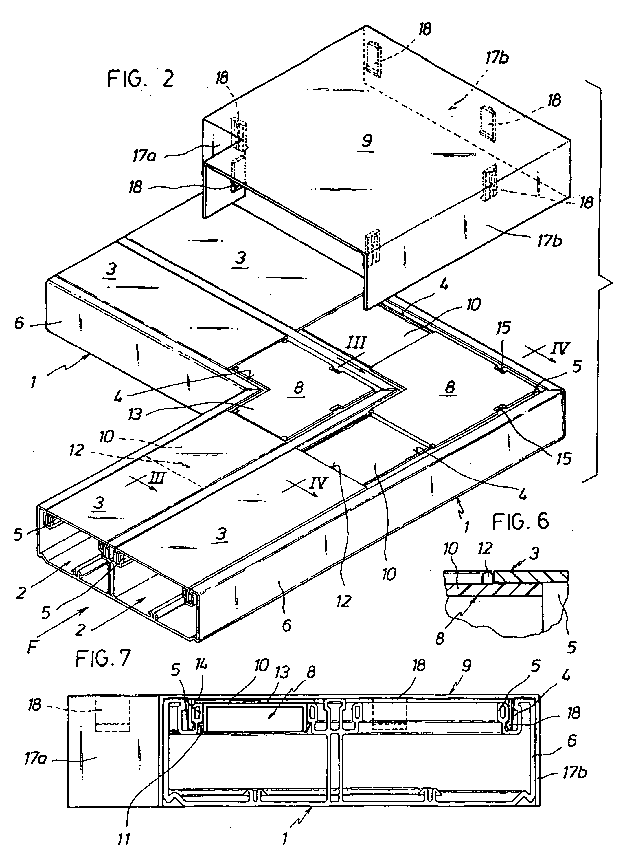
Figure 2 is an exploded perspective view, similar to Figure 1, of the covering member
and of both raceways stretches, with the angled closing members in place.
Figure 3 is a cross section view on the line III-III of Figure 2.
Figure 4 is a cross section view on the line IV-IV of Figure 2.
Figure 5 is a view on a larger scale of the detail in the ring identified as V in
Figure 3.
Figure 6 is a view on a larger scale of the detail in the ring identified as VI in
Figure 3.
Figure 7 is an elevation view, in the direction of the arrow F in Figure 2, of the
elbow according to the invention in the active position thereof.
[0009] The elbow according to the invention, as stated above, is for use with raceways for
housing electrical cable systems comprising a base section 1 having an internal bottom
surface and which is compartmented longitudinally in two or more sub-raceways 2 of
the same or different width. These raceways also comprise a cover section 3 for each
sub-raceway and each cover section 3 is provided with lateral skirts to allow for
engagement of both sections 1, 3 by insertion of the said skirts in longitudinal slots
4 provided contiguously to folds 5 capping the external walls 6 and the compartment
walls 6' of the base section 1. These raceways may assume positions in which the respective
bottom surfaces are coplanar and have end cuts 7, such that both end cuts of each
raceway may be juxtaposed over the whole extension of both.
[0010] The elbow of the invention comprises, for each sub-raceway 2, a flattened angled
closing member 8 which forms a closed conduit with the walls 6, 6' and the internal
bottom surfaces of the base section 1 (which are obviously also internal bottom surfaces
of the sub-raceways 2), which conduit may be opened for the passage of the electrical
cable systems.
[0011] Hereinafter, the position in which the elbow is duly engaged for connecting both
raceway stretches will be called the active position of the elbow or of the members
constituting it. These angled closing members 8 are provided with skirts which, in
the said active position of the elbow, penetrate in the longitudinal slots 4 of both
raceway stretches. The elbow also comprises a covering member 9 which, in the said
active position, covers from above both angled closing members 8 and is provided with
means for engagement with the base sections. Further reference will be made to these
engagement means.
[0012] The angled closing member 8 preferably comprises an outstanding centre portion 13
and two channel-like portions 10 disposed as extensions of two contiguous sides of
the centre portion 13. A step 16, defining a first height, is provided between each
channel-like portion 10 and the outstanding centre portion 13. In the said active
position, the channel-like portions 10 have the concavity thereof is directed towards
the interior of the sub-raceways 2 of the base sections 1. It is contemplated that
the channel-like portion 10 be provided, in end portions of the skirts thereof, with
barbed teeth 11 which, in the said active position, engage the folds 5, whereby the
angled member 8 is removably retained in the base sections 1.
[0013] The angled closing members 8 are also preferably provided with a transverse tab 12
extending from the outer surface thereof and which is situated close to the free edge
of the channel-like portion 10. The height of the transverse tab 12 is slightly lower
than the first height of the step 16 and is of the order of the thickness of the cover
section 3.
[0014] The outstanding centre portion 13 forms visors 14 extending laterally and which may
bear against the folds 5 of the base sections 1 in the said active position, covering
the corresponding portion of the longitudinal slots 4. The longer visors have cutaway
portions 15 leaving the longitudinal slots 4 uncovered and providing access to the
barbed teeth 11.
[0015] The channel-like portion 10, which is in cantilever relationship to the outstanding
centre portion 13, is sufficiently resilient for a cover section 3 to be able to deform
it, by flexing it, when the cover section 3 is engaged in the base section 1, such
that the cover section 3 is mounted on the transverse tab 12, as may be appreciated
in Figures 3 and 5, pressing thereagainst.
[0016] In all cases, the width of the channel-like portion 10 of the angled closing members
8 is of a smaller dimension than the corresponding internal width of the cover sections
3, whereby the channel-like portion may be comprised between the skirts of a cover
section 3.
[0017] The covering member 9 is provided with a flat upper surface, the edges of which are
straight and each of these edges is disposed at rightangles to the two immediate edges.
Two of these edges are short and form a re-entrant angle, i.e. the apex thereof is
closer to the centre region of the covering member.
[0018] The short edges are provided with respective skirts 17a and the two edges facing
the short edges are also provided with skirts 17b. Internally, the covering member
9 is also provided with barbed flanges 18, situated in parallel with the skirts 17a,
17b. In the active position of the elbow, they pass through the cutaway portions 15
and penetrate in the longitudinal slots 4, whereby the covering member 9 is removably
retained in the base sections 1.
[0019] The transverse tab 12 and the end steps 16 situated between the outstanding centre
portion 13 and the channel-like portion 10 may form stops for the cover sections 3.
Therefore, since both cover sections 3 of each sub-raceway 2 are the same (provided
always that the sub-raceways 2 are of the same width), the angled closing members
8 may be the same both for the sub-raceway situated on the inside of the elbow and
for the remaining sub-raceway, which reduces the number of parts required for closing
the elbow.
1. An elbow for the angular connection of two stretches of raceway for electrical cable
systems, each of said raceway stretches comprising: a base section (1) defining an
internal bottom surface; external walls (6); at least one compartment wall (6') providing
for the existence of at least two sub-raceways (2), said walls (6, 6') being provided
at the top end thereof with folds (5) forming longitudinal slots (4); and a cover
section for (3) each of said at least two sub-raceways (2), provided with lateral
skirts adapted to be inserted in said longitudinal slots (4); said internal bottom
surfaces of each of said base sections: being substantially coplanar and having respective
substantially juxtaposable end cuts (7) over the whole extension thereof, said elbow
being suitable for occupying an active position in which it establishes a connection
between said two raceway sections, characterized in that it comprises for each sub-raceway (2), an angled closing member (8) having skirts
which, in said active position, engage simultaneously in longitudinal slots (4) of
both raceway stretches, closing portions of a sub-raceway (2) of each stretch from
above; and a covering member (9) which, in said active position, covers said angled
closing members (8) from above and is provided with means for engagement with said
base sections (1).
2. An elbow according to claim 1, characterized in that said angled closing member (8) is provided with an outstanding centre portion (13)
and two channel-like portions (10) as extensions of said outstanding centre portion
(13), a step (16) being provided between each of said channel-like portions (10) and
said centre portion (13), defining a first height.
3. An elbow according to either of claims 1 or 2, characterized in that said skirts of said angled closing member (8) are provided with barbed teeth (11)
which, in said active position, are retentively engaged in said folds (5).
4. An elbow according to at least one of claims 1 or 3, characterized in that each of said channel-like portions (10) of said angled closing member (8) is provided
with a transverse tab (12) extending upwardly therefrom and having a second height
slightly lower than said first height.
5. An elbow according to one of claims 3 or 4, characterized in that said outstanding centre portion (13) of said angled closing member forms a visor
(14) extending laterally, which bears against said folds (5) in said active position,
said visor (14) having at least one cutaway portion (15) providing access to said
barbed teeth (11).
6. An elbow according to claim 4, characterized in that said channel-like portion (10) is adapted to flex slightly allowing said transverse
tab (12) of said channel-like portion to be engaged against said cover section (3)
in said active position.
7. An elbow according to claims 1 and 4, characterized in that said channel-like portion (10) is adapted to be comprised between said skirts of
said cover section (3) in said active position.
8. An elbow according to at least one of claims 1 to 7, characterized in that said covering member (9): [i] is provided with a flat upper surface having straight
edges, each of which forms a rightangle with the immediate edges, two of said edges
forming a re-entrant angle and respectively facing two opposite edges; said two edges
forming the re-entrant angle and said two opposite edges being provided with respective
skirts (17a, 17b); and [ii] is provided internally with barbed flanges which, in said
active position, pass through said cutaway portions (15) acceding to said longitudinal
slots (4).
1. Winkelstück zur winkelförmigen Verbindung zweier Kabelkanalstücke für elektrische
Kabelsysteme, wobei jedes der Kabelkanalstücke umfasst: ein Basisteilstück (1), eine
innere Bodenoberfläche definierend; äußere Wände (6); zumindest eine Abteilungswand
(6'), welche für die Existenz von zumindest zwei Unterkabelkanälen (2) sorgt, wobei
die Wände (6, 6') an ihrem oberen Ende mit Faltungen (5) versehen sind, die Längsschlitze
(4) bilden; und ein Deckteilstück für (3) jeden der zumindest zwei Unterkabelkanäle
(2), versehen mit seitlichen Randleisten, angepasst, um in die Längsschlitze (4) eingeführt
zu werden; wobei die inneren Oberflächen von jedem der Basisteilstücke: im Wesentlichen
koplanar sind und jeweils im Wesentlichen aneinanderbringbare Endschnitte (7) über
ihre gesamte Ausdehnung haben, wobei das Winkelstück geeignet ist, eine aktive Position
einzunehmen, in der es eine Verbindung zwischen den beiden Kabelkanalteilstücken herstellt,
dadurch gekennzeichnet, dass es für jeden Unterkabelkanal (2) umfasst, ein gewinkeltes Schließelement (8) mit
Randleisten, die in der aktiven Position gleichzeitig in die Längsschlitze (4) der
beiden Kabelkanalstücke eingreifen, wobei sie Abschnitte eines Unterkabelkanals (2)
von jedem Stück von oben schließen; und ein Deckelement (9), das in der aktiven Position
die gewinkelten Schließelemente (8) von oben bedeckt und das mit Mitteln zum Eingreifen
in die Basisteilstücke (1) versehen ist.
2. Winkelstück nach Anspruch 1, dadurch gekennzeichnet, dass das gewinkelte Schließelement (8) versehen ist mit einem hervorstehenden Zentralteil
(13) und zwei kanalähnlichen Teilen (10) als Verlängerungen des hervorstehenden Zentralteils
(13), wobei eine Stufe (16) zwischen jedem der kanalähnlichen Teile (10) und dem Zentralteil
(13) vorgesehen ist, die eine erste Höhe definiert.
3. Winkelstück nach Anspruch 1 oder 2, dadurch gekennzeichnet, dass die Randleisten des gewinkelten Schließelements (8) mit Stachelzähnen (11) versehen
sind, die in der aktiven Position haltend in die Faltungen (5) eingreifen.
4. Winkelstück nach zumindest einem der Anspräche 1 oder 3, dadurch gekennzeichnet, dass jedes der kanalähnlichen Teile (10) des gewinkelten Schließelements (8) mit einem
querlaufenden Reiter (12) versehen ist, der sich aufwärts davon erstreckt und eine
zweite Höhe hat, die geringfügig niedriger ist als die erste Höhe.
5. Winkelstück nach einem der Ansprüche 3 oder 4, dadurch gekennzeichnet, dass das hervorstehende Zentralteil (13) des gewinkelten Schließelements eine seitwärts
vorstehende Blende (14) bildet, die gegen die Faltungen (5) in der aktiven Position
drückt, wobei die Blende (14) zumindest einen Ausschnittsteil (15) hat, der Zugriff
zu den Stachelzähnen (11) ermöglicht.
6. Winkelstück nach Anspruch 4, dadurch gekennzeichnet, dass der kanalähnliche Teil (10) angepasst ist, sich geringfügig zu verbiegen, um dem
querlaufenden Reiter (12) des kanalähnlichen Teils ein Eingreifen gegen das Deckteilstück
(3) in der aktiven Position zu ermöglichen.
7. Winkelstück nach den Ansprüchen 1 und 4, dadurch gekennzeichnet, dass der kanalähnliche Teil angepasst ist, um zwischen den Randleisten des Deckteilstücks
(3) in der aktiven Position beinhaltet zu sein.
8. Winkelstück nach zumindest einem der Ansprüche 1 bis 7, dadurch gekennzeichnet, dass das Deckeelement (9): [i] mit einer flachen, oberen Oberfläche mit geraden Kanten
versehen ist, wovon jede einen rechten Winkel mit unmittelbaren Kanten bildet, wobei
zwei dieser Kanten einen zurückgezogenen Winkel bilden und jeweils zwei gegenüberliegenden
Kanten gegenüber stehen; wobei die beiden Kanten, die den zurückgezogenen Winkel bilden,
und wobei die beiden gegenüberliegenden Kanten mit jeweiligen Randleisten (17a, 17b)
versehen sind; und [ii] es ist innenseitig mit Stachelflanschen versehen, die in der
aktiven Position durch die Ausschnittsstücke (15) passieren und zu den Längsschlitzen
(4) reichen.
1. Elément coudé pour la connexion angulaire de deux longueurs de chemin de câbles pour
des systèmes de câblage électrique, chacune desdites longueurs de chemin de câbles
comprenant : une section de base (1) définissant une surface de fond interne ; des
parois externes (6) ; au moins une paroi de compartiment (6') prévoyant l'existence
d'au moins deux sous chemins de câbles (2), lesdites parois (6, 6') étant pourvues
sur leur extrémité supérieure de plis (5) formant des fentes longitudinales (4) ;
et une section de couverture (3) pour chacune desdites au moins deux sous chemins
de câbles (2), pourvue de jupes latérales adaptées pour être insérées dans lesdites
fentes longitudinales (4) ; lesdites surfaces de fond internes de chacune desdites
sections de base étant sensiblement coplanaires et ayant des découpes d'extrémité
respectives sensiblement juxtaposables (7) sur l'ensemble de leur prolongement, ledit
élément coudé étant adapté pour occuper une position active dans laquelle il établit
une connexion entre lesdites deux sections de chemin de câbles, caractérisé en ce qu'il comprend pour chaque sous chemin de câbles (2), un élément de fermeture angulaire
(8) ayant des jupes qui, dans ladite position active, se mettent en prise simultanément
avec les fentes longitudinales (4) des deux longueurs de chemin de câbles, fermant
les parties d'un sous chemin de câbles (2) de chaque longueur depuis le dessus ; et
un élément de couverture (9) qui, dans ladite position active, couvre lesdits éléments
de fermeture angulaires (8) depuis le dessus et est pourvu de moyens pour la mise
en prise avec lesdites sections de base (1).
2. Elément coudé selon la revendication 1, caractérisé en ce que ledit élément de fermeture angulaire (8) est pourvu d'une partie centrale en saillie
(13) et de deux parties de type canal (10) en tant que prolongements de ladite partie
centrale en saillie (13), un palier (16) étant prévu entre chacune des parties de
type canal (10) et ladite partie centrale (13), définissant une première hauteur.
3. Elément coudé selon l'une quelconque des revendications 1 ou 2, caractérisé en ce que lesdites jupes dudit élément de fermeture angulaire (8) sont pourvues de dents barbelées
(11) qui, dans ladite position active, sont mises en prise solidement avec lesdits
plis (5).
4. Elément coudé selon au moins une des revendications 1 ou 3, caractérisé en ce que chacune desdites parties de type canal (10) dudit élément de fermeture angulaire
(8) est pourvue d'une languette transversale (12) s'étendant vers le haut et ayant
une seconde hauteur légèrement inférieure à ladite première hauteur.
5. Elément coudé selon l'une des revendications 3 ou 4, caractérisé en ce que ladite partie centrale en saillie (13) dudit élément de fermeture angulaire forme
une visière (14) s'étendant latéralement, qui repose contre lesdits plis (5) dan ladite
position active, ladite visière (14) ayant au moins une partie crénelée (15) fournissant
un accès auxdites dents barbelées (11).
6. Elément coudé selon la revendication 4, caractérisé en ce que ladite partie de type canal (10) est adaptée pour fléchir légèrement, permettant
à ladite languette transversale (12) de ladite partie de type canal d'être mise en
prise contre ladite section de couverture (3) dans ladite position active.
7. Elément coudé selon les revendications 1 et 4, caractérisé en ce que ladite partie de type canal (10) est adaptée pour être comprise entre lesdites jupes
de ladite section de couverture (3) dans ladite position active.
8. Elément coudé selon l'au moins une des revendications 1 à 7, caractérisé en ce que ledit élément de couverture (9) : [i] est pourvu d'une surface supérieure plane ayant
des bords rectilignes, chacun d'entre eux formant un angle droit avec les bords voisins,
deux desdits bords formant un angle rentrant et faisant face respectivement aux deux
bords opposés ; lesdits deux bords formant l'angle rentrant et lesdits deux bords
opposés étant pourvus des jupes respectives (17a, 17b) ; et [ii] est pourvu à l'intérieur
de rebords barbelés qui, dans ladite position active, passent à travers lesdites parties
de crénelées (15) pour accéder auxdites fentes longitudinales (4).