|
(11) | EP 1 087 502 B1 |

| (12) | EUROPEAN PATENT SPECIFICATION |
|
|
| (54) |
Permanent magnet stepping motor Dauermagnet-Schrittmotor Moteur pas à pas à aimants permanents |
|
|
|||||||||||||||||||||||||||||||
| Note: Within nine months from the publication of the mention of the grant of the European patent, any person may give notice to the European Patent Office of opposition to the European patent granted. Notice of opposition shall be filed in a written reasoned statement. It shall not be deemed to have been filed until the opposition fee has been paid. (Art. 99(1) European Patent Convention). |
[0001] The present invention relates to a PM type stepping motor, and more specifically, it relates to a PM type stepping motor exhibiting a low level of vibration and noise.
[0002] A conventional PM type stepping motor is disclosed in JP-A-10-136631. In this conventional stepping motor, to effectively reduce higher harmonic components of the detent torque, the positions of the stator teeth (stator pole teeth) of the yokes of the stator unit deviate from positions at equal intervals. That is, when the teeth are shifted from positions of equal intervals, higher harmonic components of the detent torque appearing in principle can be canceled out in the yokes and reduced.
[0003] JP-A-5-252719 discloses a two-phase PM type stepping motor in which a member consisting of a non-magnetic material is provided between first and second phases stacked together in the axial direction. With this stepping motor, it is possible to prevent direct collision of first phase and second phase stator teeth by means of the non-magnetic member. However, exclusively aiming at a reduction in detent torque, this technique does not prevent a collision of the non-magnetic member with the stator teeth, and the sound caused by this collision results in an increase in noise.
[0004] JP-A-8-126290 discloses a method of joining yokes constituting the stator of a PM type stepping motor. This joining method will not prevent collision of a motor cover with the stator teeth, and the sound resulting from this collision also results in an increase in noise.
[0005] JP-A-3-7050 discloses a PM type stepping motor in which adjacent stator teeth of the stator yoke are connected by a bridge. In this case, the strength of the base portions of the stator teeth is increased, so that a reduction in the vibration of the stator teeth due to the electromagnetic force when the motor is driven can be expected. However, the bridge increases the number of required parts and results in an increase in production costs.
[0006] JP-A-9-233802 discloses a PM type stepping motor which is equipped with a plate spring biasing the rotor shaft in one axial direction. When the reaction force of the electromagnetic force causing an axial vibration of the stator teeth when the motor is driven acts on the rotor, the rotor also axially vibrates, involving elastic deformation of the plate spring and causing it to collide with a member such as a bearing when displaced in the biasing direction of the plate spring to thereby generate an impact sound.
[0007] In the stepping motor disclosed in JP-A-10-136631, the fourth degree higher harmonic component of the detent torque can indeed be reduced. However, there is no possibility of both the fourth degree higher harmonic and the second degree higher harmonic being reduced. Further, in some parts, a gap between the stator teeth of an outer yoke and the stator teeth of an inner yoke is extremely small, so that the leakage flux flowing between those teeth increases, resulting in a reduction in the torque generated.
[0008] On the other hand, the present inventors recognized that in a PM type stepping motor, the vibration and noise attributable to the axial vibration of the stator teeth due to the electromagnetic force when the motor is driven are not negligible, apart from the vibration and noise attributable to the higher harmonic components of the detent torque periodically generated with respect to the rotation angle of the rotor due to the magnetomotive force of the permanent magnet, as has been conventionally reported. However, in the stepping motor disclosed in JP-A-10-136631, nothing is done to reduce the noise such as impact sound attributable to the axial vibration of the stator teeth.
[0009] The present invention seeks to solve the problems of the prior art. It is an object of the present invention to provide a PM type stepping motor capable of further reducing higher harmonic components of the detent torque and, further, to provide a PM type stepping motor capable of reducing the noise attributable to the axial vibration of the stator teeth and the rotor shaft due to the electromagnetic force when the motor is driven.
[0010] This object is achieved by a PM type stepping motor as claimed in claim 1. Preferred embodiments are subject-matter of the dependent claims.
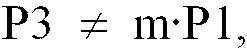
[0011] According to the present invention as defined claim 1, the pitch P1 of the rotor magnetic pole pairs, the pitch P2 of the stator teeth in the teeth groups of n sets of teeth groups and the pitch P3 of the teeth groups is:
and
where P1, P2 and P3 are electrical angles, and m and n are integers equal to or larger than 2.
[0012] Preferably an arbitrary one of the teeth groups of the outer yoke overlaps circumferentially only one of the teeth groups of the inner yoke. That is, assuming, for example, that m = 3, three stator teeth of an arbitrary teeth group of the outer yoke and three stator teeth of the teeth group of the inner yoke paired therewith are arranged circumferentially as: first of the outer yoke, first of the inner yoke, second of the outer yoke, second of the inner yoke, third of the outer yoke and third of the inner yoke, and do not circumferentially overlap other teeth groups. In the case of a plural phase stepping motor in which a plurality of stator units are stacked together, it suffices that this relationship holds true within each stator unit.
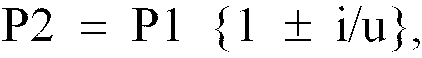
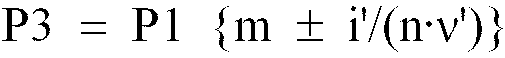
[0013] Preferably the relationships: -
and
hold true, where u is a positive integer, i is a positive integer which is not a multiple of u, i' is a positive integer which is not a multiple of n, and ν' is the degree of main higher harmonic reduced. In this case, the following relationships are even more preferable:
and
or
and
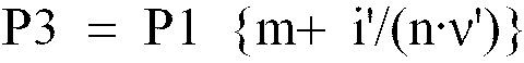
[0014] In an alternative embodiment the relationships:
and
hold true, where ν and ν' are degrees of main higher harmonics reduced, i is a positive integer which is not a multiple of m, and i' is a positive integer which is not a multiple of n. In this case, the following relationships are even more preferable:
and
or
and
[0015] Thus, in the embodiment of claim 1 the pitch P2 of the stator teeth in the teeth groups is different from the pitch P1 of the N and S pole pairs of the rotor, whereby the higher harmonic of the degree corresponding to this difference is reduced.
[0016] It is possible to assume that one teeth group consisting of m stator teeth is one tooth corresponding to m magnetic pole pairs on the rotor side. Thus, as shown in formula (2), the pitch P3 of the teeth groups is different from the pitch m·P1 of m magnetic pole pairs, so that the higher harmonic of the degree corresponding to this difference is reduced.
[0017] Further, when the pitch P3 of the teeth groups is m times the pitch P2 of the stator teeth in a teeth group, the pitch of the stator teeth is fixed over a plurality of teeth groups, and the boundary between teeth groups is lost. Thus, as shown in formula (3), the pitch P3 of the teeth groups is different from m times the pitch P2 of the stator teeth in a teeth group.
[0018] In this way, in the embodiment of the invention as defined in claim 1, higher harmonics of more degrees are reduced, so that the higher harmonics are efficiently reduced, thereby providing a more quiet, smooth rotation.
[0019] Further, generally speaking, it is known that when the relationship:
holds true between the rotor pole pitch PR and the stator teeth pitch PS, it is possible to reduce a plurality of higher harmonic components including the ν-th degree harmonic of the detent torque.
[0020] The higher harmonic of each degree is represented by a sine wave of a predetermined period, so that the deviation in stator teeth as shown in formula (16) may be i times PR {1/(m·ν)} (i is a positive integer which is not a multiple of m), that is, PR {i/(m·ν)}.
[0021] Thus, in the embodiment of claim 5, the pitch P2 of the stator teeth in the teeth group is as shown in formula (10), so that it is possible to reduce a plurality of higher harmonic components including the v-th degree. Further, when the relationship of the pitch P3 of a teeth group and the pitch P1 of the magnetic pole pairs of the rotor is
a plurality of higher harmonics including the v-th degree are reduced. However, since the higher harmonics generated in a teeth group can be decomposed for m rotor poles, the deviation in pitch of the teeth groups with respect to the m magnetic pole pairs on the rotor may be (1/m).
[0023] Thus, formula (11) is obtained. Thus, in the embodiment of claim 5, the pitch P3 of the teeth groups is as shown in formula (11), so that it is possible to also reduce a plurality of higher harmonics including the ν'-th degree.
[0024] Further, in the embodiment of claim 3, assuming that m·ν = u (u is a positive integer) and that i is a positive integer which is not a multiple of u, formula (4) is obtained from formula (10), and the pitch P3 of the teeth groups is as shown in formula (5) (which is the same as formula (11), so that it is possible to reduce a plurality of higher harmonics including the ν'-th degree.
[0025] Further, in the embodiment of claim 4, the "±" on the right side of formulas (4) and (5) is replaced by a combination of "-" and "+" (formulas (6) and (7)) or a combination of "-" and "-" (formulas (8) and (9)), and in the embodiment of claim 6, the "±" on the right side of formulas (10) and (11) in claim 5 is replaced by a combination of "-" and "+" (formulas (12) and (13)) or a combination of "-" and "-" (formulas (14) and (15)).
[0026] When the combination of the embodiment of claim 4 or claim 6 is selected, there is no fear of the gap between the rotor poles becoming extremely small, so that it is possible to prevent an increase in the leakage flux flowing between the rotor poles, making it possible to prevent a great reduction in the torque generated.
[0027] In the embodiment of claim 7, the stator has a construction in which a plurality of stator units are stacked together. However, due to the gap formed between the base portions of the stator teeth of adjacent stator units, even if the stator teeth vibrate in the axial direction due to the electromagnetic force when the motor is driven, it is possible to reduce the fear of the base portions of the stator teeth colliding with each other. Such a gap can be easily realized by the construction as claimed in claim 8 or claim 9.
[0028] Further, in the embodiment of claim 10, there is provided in the outer periphery in the vicinity of the forward end of the stator teeth a constraining member formed of a non-magnetic material and constraining the stator teeth, so that if electromagnetic force acts on the stator teeth when the motor is driven, it is possible to prevent deformation of the stator teeth. It is not absolutely necessary for the constraining member to be provided at the forward end of the stator teeth; it may be provided at a position in the vicinity of the forward end, where it is possible to restrain deformation of the stator teeth.
[0029] Further, in accordance with claim 11, the constraining member for constraining the stator teeth of the outer yoke and the constraining member for constraining the stator teeth of the inner yoke may be individually provided, or in accordance with claim 12 the width of the constraining member may be such as to cover from the vicinity of the forward end of the stator teeth of the outer yoke to the vicinity of the forward end of the stator teeth of the inner yoke, thereby reducing the number of parts. Further, in accordance with claim 13, a ring may be used as the constraining member, wherein this ring is fitted onto the outer periphery of the stator teeth, and wherein the wall thickness of the ring is smaller than the distance between the exciting coil opposed to a stator tooth when assembled and the stator tooth, whereby assembly can be easily conducted even if the ring is attached to the stator teeth.
[0030] Further, in accordance with claim 14, there is provided a cover collision preventing structure for preventing collision of the base portions of the stator teeth with the cover, so that even if the stator teeth vibrate in the axial direction due to the electromagnetic force when the motor is driven, it is possible to reduce the fear of the base portions of the stator teeth colliding with the cover. Such a cover collision preventing structure can be easily realized by joining the base portions of the stator teeth in contact with the cover to the cover (e.g., by soldering) in accordance with claim 15.
[0031] And, in accordance with claim 16, ribs are integrally formed in the base portions of the stator teeth by press molding, so that even if a force to axially vibrate the stator teeth is generated due to the electromagnetic force when the motor is driven, it is possible to eliminate or minimize the axial vibration of the stator teeth, so that it is possible to prevent the stator teeth from colliding with other members or minimize the impact if the collision does occur. And, since the ribs are solely integrally formed by press molding, it is possible to reduce the cost as compared with the case in which a bridge is formed as a separate member.
[0032] Further, in accordance with claim 17, two portions of the rotor shaft axially spaced apart from each other are supported by the stator side member (for example, the cover) via elastic members capable of elastic deformation in the axial direction, so that if a reaction force of the force causing axial vibration of the stator teeth due to the electromagnetic force when the motor is driven is input, it is possible to reduce the possibility of the rotor shaft colliding with the bearing, etc.
[0033] Preferred embodiments of the present invention will now be explained with reference to the drawings.
- Fig. 1
- is a sectional view of a PM type stepping motor according to the first embodiment of the present invention.
- Fig. 2
- is a development illustrating the positional relationship between permanent magnets and stator teeth.
- Fig. 3
- is a waveform diagram illustrating the operation of the embodiment.
- Fig. 4
- is a waveform diagram illustrating a conventional example.
- Fig. 5
- is a diagram showing the results of frequency analysis of higher harmonic component of detent torque.
- Fig. 6
- is a development illustrating the positional relationship of permanent magnets and stator teeth in the second embodiment.
- Fig. 7
- is a sectional view of a PM type stepping motor according to the third embodiment.
- Fig. 8
- is a plan view of an inner yoke.
- Fig. 9
- is a plan view of the inner yoke with a spacer superimposed thereon.
- Fig. 10
- is a plan view of an outer yoke.
- Fig. 11
- is a sectional view showing a modification of the inner yoke.
- Fig. 12
- is a perspective view of a modification of the stator tooth.
- Fig. 13
- is a perspective view of the modification of the stator tooth seen from a different direction.
- Fig. 14
- is a side view of the modification of the stator tooth.
- Fig. 15
- is a perspective view of the outer yoke and the inner yoke of the fourth embodiment.
- Fig. 16
- is a sectional view of the PM type stepping motor of the fourth embodiment.
- Fig. 17
- is a diagram illustrating how the stator teeth are deformed.
[0034] Figs. 1 and 2 show a first embodiment of the present invention. In this embodiment, the present invention is applied to a two phase PM type stepping motor.
[0035] That is, the PM type stepping motor 1 of this embodiment is equipped with a rotor 10 and a stator 20 surrounding the rotor 10 in a non-contact state.
[0036] The rotor 10 has a rotator shaft 11 which is rotatably supported at two positions axially spaced apart from each other by covers 30A and 30B as stator side members via bearings 30a and 30b. However, between the rotator shaft 11 and the bearings 30a and 30b, there are provided plate springs 31a and 31b as elastic members capable of elastic deformation in the axial direction, whereby the rotator shaft 11 is axially movable relative to the covers 30A and 30B within the range in which the elastic deformation of the plate springs 31a and 31b is possible.
[0037] Further, at positions of the rotator shaft 11 between the covers 30A and 30B, there are fixed cylindrical permanent magnets 12A and 12B which are axially spaced apart from each other. These permanent magnets 12A and 12B are of the same construction, and as shown in Fig. 2(a), which illustrates a development of the outer peripheral surface thereof, pairs of an N pole and an S pole are alternately polarized at a fixed pitch P1 in the circumferential direction.
[0038] On the other hand, the stator 20 includes first and second stator units 21A and 21B axially stacked together to correspondent with the permanent magnets 12A and 12B, respectively. The stator units 21A and 21B are the same members except that there is some deviation in the circumferential positions of their stator teeth described below and that they are axially reversed with respect to each other.
[0039] That is, each of the first and second stator units 21A and 21B is equipped with an exciting coil 22, an outer yoke 23 and an inner yoke 24, and the exciting coil 22 is formed by winding wire into a cylindrical form and performing insulation processing on it, the exciting coil 22 being placed between the outer yoke 23 and the inner yoke 24.
[0040] The outer yoke 23 is equipped with a cylindrical housing portion 23a covering the outer peripheral surface of the exciting coil 22, a disc-like plate portion 23b covering the end surface of the exciting coil 22 on the side facing the cover 30A or 30B, and a plurality of comb-like stator teeth 25 (stator pole teeth) extending axially from the center of the plate portion 23b along the inner peripheral surface of the exciting coil 22. The housing portion 23a, the plate portion 23b and the stator teeth 25 of the outer yoke 23 are formed integrally out of a steel plate by pressing.
[0041] The inner yoke 24 is equipped with a disc-like plate portion 24a covering the end surface of the exciting coil 22 farther from the cover 30A or 30B, and a plurality of comb-like stator teeth 26 (stator pole teeth) extending axially from the center of the plate portion 24a along the inner peripheral surface of the exciting coil 22. The plate portion 24a and the stator teeth 26 of the outer yoke 23 is formed integrally out of a steel plate by pressing.
[0042] The number of stator teeth 25 of the outer yoke 23 is the same as the number of stator teeth 26 of the inner yoke 24 (which is 12 in this embodiment), and the stator teeth 25 and 26 are alternately arranged on the inner peripheral surface of the exciting coil 22 so as not to be in contact with each other.
[0043] Fig. 2(b) is a development of a part of the outer yoke 23 and the inner yoke 24, showing six to seven stator teeth 25a through 25g and stator teeth 26a through 26f and 26l for the outer yoke 23 and the inner yoke 24 of each of the first stator unit 21A and the second stator unit 21B. The specific positions of the stator teeth 25 and 26 will be described below.
[0044] The first stator unit 21A and the second stator unit 21B are placed between the covers 30A and 30B and secured in position in the condition in which they are stacked together such that the circumferential positions of the stator teeth 25 and 26 are shifted by a predetermined angle with respect to each other.
[0045] In the motor 1, constructed as described above, a rotating magnetic field is formed by sequentially switching the current caused to flow through the exciting coils 22 by a drive circuit (not shown), and the rotor 10 is driven.
[0046] Next, the specific positions of the stator teeth 25 and 26 of this embodiment will be described. There are provided twelve stator teeth 25 and twelve stator teeth 26. Of these, six stator teeth 25 and six stator teeth 26 are combined to constitute one set. That is, there are two sets, each set being appropriately divided into teeth groups as described below. A description will only be given of the positions of six stator teeth 25 and six stator teeth 26, i.e., one set.
[0047] In this embodiment, the relationships of formulas (4) and (5) hold true in order that the relationships of formulas (1) through (3) may hold true. More specifically, the relationships of formulas (8) and (9) hold true.
[0048] In the motor 1 of this embodiment, the values for determining the pitches P2 and P3 are as follows:
m = 3, n = 2, u = 32, i = 1, i' = 1, ν' = 4.
[0049] That is, in this embodiment, each of the yokes 23 and 24 is equipped with six stator teeth 25a through 25f, 26a through 26f. Regarding the outer yoke 23, the six stator teeth 25a through 25f are divided into two teeth groups each consisting of three stator teeth (m = 3), namely 25a through 25c, and 25d through 25f. Regarding the inner yoke 24 also, the six stator teeth 26a through 26f are divided into two teeth groups each consisting of three stator teeth, namely 26a through 26c, and 26d through 26f.
[0050] Each teeth group of the outer yoke 23 and the inner yoke 24 is set such that, for example, one teeth group 25a through 25c of the outer yoke 23 circumferentially overlaps only one teeth group 26a through 26c of the inner yoke 24. This relationship remains the same if the number of teeth groups or the number of stator teeth constituting each teeth group is changed.
[0052] The positions of the stator teeth 25a through 25f and 26a through 26f are determined so as to achieve these pitches P2 and P3.
[0053] In this construction, since ν' = 4, it is possible to reduce the fourth-degree higher harmonic of the detent torque. Fig. 3 is a waveform diagram, which was obtained by actually performing measurement on a two phase PM type stepping motor with 48 steps per revolution to which the construction of this embodiment is applied. As can be seen from comparison with Fig. 4, which is a diagram obtained by performing a similar measurement on a conventional PM type stepping motor, the amplitude is substantially reduced. And, through frequency analysis of the results shown in Figs. 3 and 4, a substantial reduction in the fourth degree higher harmonic has been ascertained, as shown in Fig. 5.
[0054] Further, in this embodiment, it is possible to prevent the gap between the stator teeth 25 of the outer yoke 23 and the stator teeth 26 of the inner yoke 24 from becoming extremely small. That is, for example, the pitch P4 between the stator tooth 25d and the stator tooth 26c shown in Fig. 2(b) will be considered. Assuming that the stator teeth 25 and the stator teeth 26 are arranged at a fixed pitch, the pitch P2 is equal to the pitch P1, so that P4 = P1/2 . However, if the pitch P2 of the stator teeth 25 and the stator teeth 26 is not fixed as in the case, for example, of the PM type stepping motor of the above-mentioned JP-A-10-136631, the pitch between adjacent stator teeth 25 and stator teeth 26 is large in some places and small in other places, so that the minimum value of the pitch between adjacent stator teeth 25 and 26 must be smaller than P1/2.
[0055] However, when, as in this embodiment, the pitches P2 and P3 are set according to formulas (8) and (9) (which is the same when formulas (6) and (7) are selected), the shift direction due to the pitch P2 and the shift direction due to pitch P3 cancel out each other, whereby it is possible to prevent the pitch P4 from becoming extremely small.
[0056] This will be specifically illustrated with reference to Fig. 2(b). When, for example, in the condition before the setting of the pitches P2 and P3, in which the pitch P2 is equal to the pitch P1, and the positions of the central stator teeth 25b and 26b of the teeth groups 25a through 25c and 26a through 26c are considered as fixed, the pitch P2 is set according to formula (8) with respect to these fixed positions, the stator teeth 25a and 25c approach the stator tooth 25b, and the stator teeth 26a and 26c approach the stator tooth 26b. A similar movement is also generated with respect to the teeth groups 25d through 25f and 26d through 26f. As a result, the distance between the end portions of the teeth groups changes such that the end portions are spaced apart from each other (the pitch P4 increases). Thus, if, as a result of setting the pitch P3 of the teeth groups according to formula (9), the distance between the end portions of the teeth groups changes such that the end portions approach each other (that is, if the pitch P4 decreases), an increase in the pitch P4 is already achieved due to the setting of the pitch P2, so that it is possible to prevent the pitch P4 from becoming extremely small. When, instead of formulas (8) and (9), formulas (6) and (7) are adopted, an extreme reduction in the pitch can also be prevented. In the construction of this embodiment, the minimum value of the pitch P4 is equal to 0.88·(P1/2), which is relatively large as compared with the minimum value of the pitch in the case of the motor disclosed in JP-A-10-136631, which is 0.83·(P1/2).
[0057] When the pitch P4 is not extremely small, it is possible to prevent an increase in the leakage flux flowing between the stator teeth 25d and 26c, whereby it is possible to prevent a substantial reduction in the torque generated.
[0058] Further, in this embodiment, plate springs 31 a and 31 b are provided between the rotator shaft 11 and the bearing 30a and between the rotator shaft 11 and the bearing 30b, respectively, so that a further reduction in vibration can be advantageously achieved. That is, even when a force causing axial vibration of the stator teeth 25 and 26 is generated due to the electromagnetic force when the motor 1 is driven, and the reaction force of that force acts on the rotor 10 through the permanent magnets, the rotator shaft is axially movable within the range in which the elastic deformation of the plate springs 31 a and 31 b is possible, so that the rotator shaft 11 does not collide with the bearings 30a and 30b to thereby reduce the possibility of generating sliding and impact sound.
[0059] Fig. 6 is a diagram showing a second embodiment of the present invention; it is a development similar to Fig. 2. Since the general construction of the PM stepping motor of this embodiment is the same as that of the first embodiment, the motor is not shown and an overlapping description is omitted, and the components and the positions which are the same as those of the first embodiment are indicated by the same reference numerals.
[0060] In this embodiment, the relationships of formulas (10) and (11) hold true in order that the relationships of formulas (1) through (3) may hold true. More specifically, the relationships of formulas (14) and (15) hold true.
[0061] In the motor of this embodiment, the values for determining the pitches P2 and P3 are as follows:
m = 3, n = 2, i = 2, v = 4, i' = 1, ν' = 2.
[0062] That is, in this embodiment also, the six stator teeth 25a through 25f of the outer yoke 23 are divided into two teeth groups each consisting of three stator teeth (m = 3) 25a through 25c, 25d through 25f, and the six stator teeth 26a through 26f of the inner yoke 24 are divided into two teeth groups each consisting of three stator teeth 26a through 26c, 26d through 26f. From formulas (14) and (15), the pitches P2 and P3 are obtained as follows:
[0063] In this construction, since ν = 4, the fourth-degree higher harmonic of the detent torque is reduced by the difference between the pitch P2 of the stator teeth 25a through 25c, 25d through 25f, 26a through 26c, and 26d through 26f in the teeth groups and the pitch P1 of the rotor pole pairs, and, since ν' = 2, the second-degree higher harmonic of the detent torque is reduced by the difference between the pitch P3 between the teeth groups 25a through 25c and 25d through 25f and between the teeth groups 26a through 26c and 26d through 26f. Thus, unlike the conventional PM type stepping motor, it is capable of reducing higher harmonics of many degrees, whereby it is possible to achieve a more quiet and smooth rotation.
[0064] Further, in this embodiment also, formulas (14) and (15) are adopted to set the pitches P2 and P3, so that as in the first embodiment described above, the pitch P4 is increased when the pitch P2 is set. Thus, if the pitch P4 becomes small when setting the pitch P3, it is possible to prevent its becoming extremely small, so that it is possible to prevent an increase in the leakage flux flowing between the stator teeth 25d and 26c, whereby it is possible to prevent a great reduction in the torque generated. When, instead of formulas (14) and (15), formulas (12) and (13) are adopted, it is also possible to prevent the pitch from becoming extremely small.
[0065] Figs. 7 through 10 are diagrams showing a third embodiment of the present invention. Fig. 7 is a sectional view of a two phase PM type stepping motor 1 similar to that of Fig. 1. The components and positions which are the same as those of the first embodiment are indicated by the same reference numerals, and a description thereof will be omitted. In this embodiment also, the circumferential positional relationship of the stator teeth 25 and 26 is set according to formulas (6) and (7), formulas (8) and (9), formulas (12) and (13), and formulas (14) and (15) as in the first and second embodiments described above.
[0066] In this embodiment, a disc-like spacer 40 is provided between the first stator unit 21A and the second stator unit 21B. However, at the center of the spacer 40, there is formed a circular opening 40a having a diameter approximately the same as the diameter d of the plate portion 24a of the inner yoke 24 (see Fig. 8), whereby, as shown in Fig. 9. the spacer 40 is only in contact with the plate portion 24a of the inner yoke 24, and is not in contact with the base portions of the stator teeth 26.
[0067] Thus, there is formed an axial gap 41 between the first stator unit 21A and the second stator unit 21B which are axially adjacent to each other, whereby the base portions of the stator teeth 26 are not in contact with each other.
[0068] On the other hand, the plate portions 23b of the outer yokes 23 are in contact with the covers 30A and 30B, respectively, and of the portion in contact with the covers 30A and 30B, a welding point w is set at the base portions of the stator teeth 25, and spot welding is performed at the welding point w to join the base portions of the stator teeth 25 to the cover 30A and 30B, respectively. More specifically, in this embodiment, as shown in Fig. 10, a welding point w is set at every other base portion of the stator teeth 25 to perform spot welding, whereby the stator teeth 25 are not easily detached from the covers 30A and 30B.
[0069] In this embodiment, which has the above-described construction, even if a force causing axial vibration of the stator teeth 25 and 26 is generated due to the electromagnetic force when the motor 1 is driven, noise attributable thereto is no easily generated. The first reason for this is that in this embodiment like the first embodiment, plate springs 31a and 31b are provided between the rotator shaft 11 and the bearing 30a and between the rotator shaft 11 and the bearing 30b.
[0070] The second reason is that a gap 41 is formed. That is, even if the stator teeth 26 of the inner yoke 24 axially vibrate due to the electromagnetic force when the motor 1 is driven, it is possible, due to the formation of the gap 41, to avoid collision of the stator teeth 26 on the first stator unit 21A side with the stator teeth 26 on the second stator unit 21B side. Further, by reducing the contact portion of the inner yokes 24, it is possible to reduce the magnetic interference between the first and second stator units 21A and 21B, so that it is possible to prevent fluctuation in electromagnetic force or unevenness in rotation attributable thereto.
[0071] The third reason is that the stator teeth 25 are not easily separated from the covers 30A and 30B. That is, even if an axial force is exerted on the stator teeth 25 of the outer yoke 23 due to the electromagnetic force when the motor 1 is driven, the stator teeth 25 cannot collide with the covers 30A and 30B when returning to the original positions as long as the stator teeth 25 are not separated from the covers 30A and 30B.
[0072] Thus, in the construction of this embodiment, it is possible to reduce higher harmonic components of the detent torque due to an action similar to that of the first and second embodiments and, further, to reduce the vibration caused by the force axially vibrating the stator teeth 25 and 26 due to the electromagnetic force when the motor 1 is driven, so that it is advantageously possible to achieve a very quiet and smooth rotation.
[0073] In this embodiment, the construction in which the base portions of the stator teeth 25 of the outer yoke 23 are joined to the covers 30A and 30B by welding corresponds to the structure for preventing collision with the cover.
[0074] While in the third embodiment the gap 41 is formed by utilizing the spacer 40, this should not be construed restrictively. It is also possible to form the gap 41 by deforming the base portions of the stator teeth 26 in the direction away from the adjacent inner yoke 24. More specifically, as shown, for example, in Fig. 11(a), the gap 41 may be formed by deforming the base portions of the stator teeth 26 in a step-like manner, or as shown in Fig. 11(b), the gap 41 may be formed by bending the base portions of the stator teeth 26. The configurations as shown in Fig. 11(a) and 11(b) can be easily obtained when forming the inner yoke 24 by pressing, so that no increase in production cost is involved.
[0075] Further, as for the construction for reducing the noise caused by the electromagnetic force when the motor 1 is driven, it is also possible to adopt a construction as shown in Figs. 12 through 14. Fig. 12 is a perspective view of one stator tooth 26 of the inner yoke 24 and the plate portion 24a in the vicinity thereof, Fig. 13 is a perspective view as seen from the opposite direction, and Fig. 14 is a side view of the same portion. Ribs 42a, 42b and 42c extending along the radial direction of the inner yoke 24 are integrally formed at the center and on both sides of the base portion of the stator tooth 26 by pressing. It is possible to adopt a similar construction for the stator teeth 25 of the outer yoke 23. And, when the ribs 42a, 42b and 42c are formed on the stator teeth 25 and 26, even if a force causing axial vibration of the stator teeth 25 and 26 is generated due to the electromagnetic force when the motor 1 is driven, it is possible to eliminate or minimize the vibration of the stator teeth 25 and 26, so that it is possible to prevent the stator teeth 25 and 26 from colliding with the covers 30A and 30B and other stator teeth 26 close thereto or minimize the impact, and it is possible to eliminate or minimize the noise.
[0076] Further, in the construction shown in Figs. 12 through 14, the ribs 42a, 42b and 42c are integrally formed by stamping, so that unlike the construction in which separate members are fastened afterwards, no increase in production cost is involved.
[0077] Figs. 15 through 17 show the fourth embodiment of the present invention. Fig. 15 is a perspective view of the outer yoke 23 and the inner yoke 24. The general construction of the PM type stepping motor of this embodiment is the same as that of the first embodiment, so it is not shown in the drawing and a description thereof will be omitted. The components and positions which are the same as those of the first embodiment are indicated by the same reference numerals, and a description thereof will be omitted.
[0078] And, in this embodiment, as shown in Fig. 15, in the outer periphery of the forward ends of the stator teeth 25 of the outer yoke 23, there is provided a ring 27 serving as a restraining member for restraining outward and radial deformation of the stator teeth 25, and due to this ring 27, outward deformation of the stator teeth 26 of the inner yoke 24 is also restrained. That is, the ring 27 is formed of a non-magnetic material, such as aluminum or brass, and, as shown in the sectional view of Fig. 16, the width of the ring is such that when the ring 27 is attached to the stator teeth 25 of the outer yoke 23 and the inner yoke 24, it covers the axial length from the forward ends of the stator teeth 25 of the outer yoke 23 to the forward ends of the stator teeth 26 of the inner yoke 24 and, the wall thickness of the ring is such that when the ring 27 is attached to the stator teeth 25 and 26, a margin is left between the ring 27 and the exciting coil 22, and that outward deformation of the stator teeth 25 and 26 can be restrained.
[0079] For example, after press-fitting the ring 27 onto the outer peripheral surface of the stator teeth 25 of the outer yoke 23, the stator teeth 26 of the inner yoke 24 are forced into this ring 27, whereby the ring 27 is attached to the stator teeth 25 of the outer yoke 23 and the stator teeth 26 of the inner yoke 24.
[0080] When an electromagnetic force acting radially or axially when the motor is driven is applied to the stator teeth 25 and 26, due to the low stiffness of these stator teeth 25 and 26, the stator teeth 25 and 26 are deformed radially outward each time there is a change in the opposed positions of the magnetic pole of the rotor 10 and the stator teeth 25 and 26 to thereby also cause axial deformation, thereby generating vibration and causing noise. That is, as compared with the case in which the motor is not driven as shown in Fig. 17(a), in the case when the motor is driven as shown in Fig. 17(b), the stator teeth are deformed radially outward, and the nearer the forward end, the greater the deformation. While Fig. 17(b) only shows the stator teeth of one of the inner and outer yokes, this phenomenon is in fact observed with the stator teeth 25 and 26 of both the outer yoke 23 and the inner yoke 24.
[0081] However, in this embodiment, there is provided the ring 27, which is engaged with the portions near the forward ends of the stator teeth 25 and 26, so that it is possible to restrain the radial and outward deformation of the stator teeth 25 and 26. Thus, the deformation of the stator teeth 25 and 26 is restrained, so that the vibration due to the deformation of the stator teeth 25 and 26 is also restrained.
[0082] The deformation of the stator teeth 25 and 26 might be restrained, for example, by filling the gap between the stator teeth 25 and 26 and the exciting coil 22 with resin or the like, or embedding metal. However, resin has low rigidity, and it is necessary to fill the whole gap between the stator teeth 25 and 26 and the exciting coil 22 with resin to fix the teeth, with the result that the assembly takes much time. On the other hand, the method of embedding metal is difficult from the viewpoint of production. Further, an inadvertent stress could be applied to the stator teeth 25 and 26. However, in this embodiment, it is only necessary to attach the ring 27 to the stator teeth 25 and 26, so that the assembly is easy to perform. Further, since the ring 27 is formed so as to leave a margin between it and the exciting coil 22, it is easy to perform the assembly even when mounting the stator teeth 25 and 26 and the exciting coil 22.
[0083] Further, as shown in Fig. 17, the amount of deformation is larger at the forward ends of the stator teeth 25 and 26 than at the base portions thereof. In this embodiment, however, a ring is provided in the vicinity of the forward ends of the stator teeth 25 and 26, which means the ring 27 is provided where the amount of deformation of the stator teeth 25 and 26 is maximum, whereby it is possible to effectively restrain the deformation of the stator teeth 25 and 26.
[0084] While in this embodiment the stator teeth 25 and 26 of both the outer yoke 23 and the inner yoke 24 are constrained, this should not be construed restrictively. It is also possible to provide two rings: a ring for constraining the stator teeth 25 of the outer yoke 23 and a ring for constraining the stator teeth 26 of the inner yoke 24. However, by constraining the stator teeth 25 and 26 of both the outer yoke 23 and the inner yoke 24 by the same ring 27, it is possible to restrain the increase in the number of parts of the motor to a minimum level.
[0085] Further, while in this embodiment the ring 27 is provided as the constraining member for the stator teeth 25 and 26, it is not absolutely necessary for the constraining member to be in the form of a ring. For example, it may be a member in the form of a coil, and any type of member is applicable as long as it is capable of restraining the deformation of the stator teeth 25 and 26.
[0086] Further, while in the above-described embodiment the wall thickness of the ring 27 is such that a space is left between the ring 27 and the exciting coil 22 when the ring 27 is attached to the stator teeth 25 and 26, leaving such space is not absolutely necessary; it is only necessary for the wall thickness to be slightly smaller than the distance between the ring 27 and the exciting coil 22. The essential thing is that the wall thickness be such that when assembling the stator teeth 25 and 26 and the exciting coil 22, the assembly can be easily performed even when the ring 27 is attached.
[0087] Further, in this embodiment, it is possible to form on the side of the ring 27 opposed to the stator teeth 25 and 26 recesses or the like of a configuration in conformity with the stator teeth 25 and 26 for the positioning of the stator teeth 25 and 26, and use them as a guide when engaging the stator teeth 26 and 26 with the ring 27.
[0088] Further, while in the above-described embodiment a ring 27 is used that covers the forward ends of the stator teeth 25 and 26, it is not absolutely necessary for the ring to cover up to the forward ends; it suffices to cover the portions near the forward ends so that the deformation of the stator teeth 25 and 26 can be restrained.
[0089] While in the above-described embodiments the present invention is applied to a two phase PM type stepping motor 1, the field of application of the present invention is not restricted to this. The present invention is also applicable to a PM type stepping motor of one phase or three or more phases.
[0090] Further, while in the above-described first and second embodiments the pitches P2 and P3 are set so as to aim at a reduction in the fourth-degree higher harmonic component of the detent torque or the second-degree higher harmonic component and the fourth-degree higher harmonic component of the detent torque, this should not be construed restrictively. For example, in the case of a three phase PM type stepping motor, it is possible to adopt a construction in which the fourth-degree higher harmonic component and the sixth-degree higher harmonic component can be reduced, and, in the case of a four phase PM type stepping motor, it is possible to adopt a construction in which the fourth-degree higher harmonic component and the eighth-degree higher harmonic component can be reduced, and the selection can be arbitrarily effected.
[0091] As described above, in the embodiments of the invention claimed in claims 1 through 6, the pitch P2 of the stator teeth in the teeth groups and the pitch P3 of the teeth groups are appropriately set, so that harmonic components of higher degree can be reduced, whereby these higher harmonics can be efficiently reduced and a more quiet and smooth rotation can be achieved.
[0092] In particular, in the embodiment of the invention claimed in claim 4 or 6, it is possible to prevent the gap between the stator teeth from becoming extremely small, so that it is possible to prevent an increase in the leakage flux flowing between the stator teeth, whereby it is possible to avoid a great reduction in the torque generated.
[0093] Further, in the embodiments of the invention claimed in claims 7 through 17, even if a force causing axial vibration of the stator teeth of the outer yoke and the inner yoke is generated due to the electromagnetic force when the PM type stepping motor is driven, vibration and impact sound are not generated or not easily generated, so that it is possible to obtain a quieter PM type stepping motor.
[0094] In particular, according to the embodiments of the invention claimed in claims 7 through 9, it is possible to reduce the magnetic interference between the stator units, so that it is possible to prevent fluctuation in force and unevenness in rotation attributable thereto. Further, according to the embodiments of the invention claimed in claims 10 through 13, even if a force tending to cause radial vibration of the stator teeth is generated, there is no such vibration, so that it is also possible to restrain the vibration attributable to the force tending to cause radial vibration.
1. A PM type stepping motor comprising a rotor (10) in which N and S magnetic pole pairs
of permanent magnets (12A, 12B) are alternately arranged circumferentially on the
outer peripheral surface at a fixed pitch P1, and a stator (20) surrounding the rotor,
the stator having a stator unit (21A, 21B) equipped with an outer yoke (23) and an inner yoke (24), the outer and inner yokes having comb-teeth-like stator teeth (25, 26) on the inner periphery,
wherein each of the outer and inner yokes is equipped with n sets of teeth groups each consisting of m stator teeth, and wherein assuming that the pitch of the stator teeth in the teeth groups is P2 and the pitch of the teeth groups is P3, the relationship between P1, P2 and P3 is defined by the following formulae (1) to (3)

and

where P1, P2 and P3 are electrical angles, and m and n are integers equal to or larger than 2.
the stator having a stator unit (21A, 21B) equipped with an outer yoke (23) and an inner yoke (24), the outer and inner yokes having comb-teeth-like stator teeth (25, 26) on the inner periphery,
wherein each of the outer and inner yokes is equipped with n sets of teeth groups each consisting of m stator teeth, and wherein assuming that the pitch of the stator teeth in the teeth groups is P2 and the pitch of the teeth groups is P3, the relationship between P1, P2 and P3 is defined by the following formulae (1) to (3)
and
where P1, P2 and P3 are electrical angles, and m and n are integers equal to or larger than 2.
2. The motor according to Claim 1, wherein the teeth groups of the outer and inner yokes
(23, 24) are set such that an arbitrary one of the teeth groups of the outer yoke
(23) overlaps circumferentially only one of the teeth groups of the inner yoke.
3. The motor according to Claim 1 or 2, wherein the relationships:
and
hold true, where u is a positive integer, i is a positive integer which is not a multiple of u, i' is a positive integer which is not a multiple of n, and ν' is the order of main higher harmonic reduced.
and
hold true, where u is a positive integer, i is a positive integer which is not a multiple of u, i' is a positive integer which is not a multiple of n, and ν' is the order of main higher harmonic reduced.
4. The motor according to Claim 3, wherein the relationships:

and
or the relationships:

and

hold true.
and
or the relationships:
and
hold true.
5. The motor according to Claim 1 or 2, wherein the relationships:
and

hold true, where ν and ν' are degrees of main higher harmonics reduced, i is a positive integer which is not a multiple of m, and i' is a positive integer which is not a multiple of n.
and
hold true, where ν and ν' are degrees of main higher harmonics reduced, i is a positive integer which is not a multiple of m, and i' is a positive integer which is not a multiple of n.
6. The motor according to Claim 5, wherein the relationships:
and

or the relationships:

and
hold true.
and
or the relationships:
and
hold true.
7. The motor according to any one of claims 1 through 6, wherein the stator (20) has
a construction in which a plurality of said stator units (21A, 21 B) are stacked together
and wherein an axial gap (41) is formed between the base portions of the stator teeth
(25, 26) of the stator units axially adjacent to each other so that the base portions
may not come into contact with each other.
8. The motor according to claim 7, wherein there is provided between the stator units
(21A, 21B) axially adjacent to each other a spacer (40) which is in contact with only
the portions other than the base portions of the stator teeth (25, 26) of the stator
units to thereby form the axial gap (41).
9. The motor according to claim 7, wherein the base portions of the stator teeth (25,
26) are deformed in the direction away from the base portions of the other stator
teeth axially adjacent thereto to thereby form the axial gap.
10. The motor according to any one of claims 1 through 9, wherein there is provided in
the outer periphery in the vicinity of the forward end of the stator teeth (25, 26)
a constraining member (27) formed of a non-magnetic material and constraining the
stator teeth.
11. The motor according to claim 10, wherein a constraining member for constraining the
stator teeth (25) of the outer yoke (23) and a constraining member for constraining
the stator teeth (26) of the inner yoke (24) are individually provided.
12. The motor according to claim 10, wherein the width of the constraining member (27)
is such as to cover the stator teeth from the vicinity of the forward end of the stator
teeth (25, 26) of the outer yoke (23) to the vicinity of the forward end of the stator
teeth of the inner yoke (24).
13. The motor according to any one of claims 10 through 12, wherein the constraining member
(27) is a ring.
14. The motor according to any one of the preceding claims, wherein there is provided
a cover collision preventing structure (w) for preventing collision of the stator
teeth (25, 26) with the covers (30A, 30B).
15. The motor according to claim 14, wherein the cover collision preventing structure
(w) has a construction in which the base portions of the stator teeth (25, 26) in
contact with the cover (30A, 30B) are secured to the cover.
16. The motor according to any one of the preceding claims, wherein ribs (42a-42c) are
integrally formed by press molding at the base portions of the stator teeth (25, 26).
17. The motor according to any one of the preceding claims, wherein
the shaft (11) of the rotor is rotatably supported by members (30A, 30B, 30a, 30b) on the stator side at two positions axially separated from each other, and
said two positions of the rotator shaft are supported by said members in the axial direction via elastic members (31a, 31b) capable of elastic deformation in the axial direction.
1. Permanentmagnet-Schrittmotor mit einem Rotor (10), in dem N- und S-Magnetpolpaare
von Permanentmagneten (12A, 12B) in Umfangsrichtung auf der äußeren Umfangsfläche
in einem festen Teilungsmaß P1 abwechselnd angeordnet sind, und einem Stator (20),
der den Rotor umgibt, wobei der Stator eine Statoreinheit (21A, 21B) umfaßt, die mit
einem äußeren Joch (23) und einem inneren Joch (24) versehen ist, welche beide auf
dem Innenumfang kammartige Statorzähne (25, 26) besitzen,
wobei sowohl das äußere Joch als auch das innere Joch mit n Sätzen von Zahngruppen versehen ist, die je aus m Statorzähnen bestehen, und wobei unter der Annahme, daß das Teilungsmaß der Statorzähne in den Zahngruppen P2 und das Teilungsmaß der Zahngruppen P3 ist, die Beziehung zwischen P1, P2 und P3 durch folgende Gleichungen (1) bis (3) bestimmt ist.


und

worin P1, P2 und P3 elektrische Winkel sind und m und n ganze Zahlen gleich oder größer als 2 sind.
wobei sowohl das äußere Joch als auch das innere Joch mit n Sätzen von Zahngruppen versehen ist, die je aus m Statorzähnen bestehen, und wobei unter der Annahme, daß das Teilungsmaß der Statorzähne in den Zahngruppen P2 und das Teilungsmaß der Zahngruppen P3 ist, die Beziehung zwischen P1, P2 und P3 durch folgende Gleichungen (1) bis (3) bestimmt ist.
und
worin P1, P2 und P3 elektrische Winkel sind und m und n ganze Zahlen gleich oder größer als 2 sind.
2. Motor nach Anspruch 1, bei dem die Zahngruppen des äußeren und des inneren Jochs (23,
24) so gesetzt sind, daß eine willkürliche der Zahngruppen des äußeren Jochs (23)
in Umfangsrichtung nur eine der Zahngruppen des inneren Jochs überlappt.
3. Motor nach Anspruch 1 oder 2, bei dem die folgenden Beziehungen gelten

und

worin u eine positive ganze Zahl ist, i eine positive ganze Zahl ist, die kein Mehrfaches von u ist, i' eine positive ganze Zahl ist, die kein Mehrfaches von n ist und ν' die Größenordnung der reduzierten Hauptoberschwingung ist.
und
worin u eine positive ganze Zahl ist, i eine positive ganze Zahl ist, die kein Mehrfaches von u ist, i' eine positive ganze Zahl ist, die kein Mehrfaches von n ist und ν' die Größenordnung der reduzierten Hauptoberschwingung ist.
4. Motor nach Anspruch 3, bei dem die Beziehungen
und

oder die Beziehungen

und

gelten.
und
oder die Beziehungen
und
gelten.
5. Motor nach Anspruch 1 oder 2, bei dem die folgenden Beziehungen

und

gelten, worin ν und ν' Grade reduzierter Hauptoberschwingungen sind, i eine positive ganze Zahl ist, die kein Mehrfaches von m ist, und i' eine positive ganze Zahl ist, die kein Mehrfaches von n ist.
und
gelten, worin ν und ν' Grade reduzierter Hauptoberschwingungen sind, i eine positive ganze Zahl ist, die kein Mehrfaches von m ist, und i' eine positive ganze Zahl ist, die kein Mehrfaches von n ist.
6. Motor nach Anspruch 5, bei dem die Beziehungen

und
oder die Beziehungen

und

gelten.
und
oder die Beziehungen
und
gelten.
7. Motor nach einem der Ansprüche 1 bis 6, bei dem der Stator (20) einen Aufbau hat,
in welchem eine Vielzahl der Statoreinheiten (21A, 21 B) gestapelt sind und bei dem
ein axialer Spalt (41) zwischen Basisbereichen der Statorzähne (25, 26) der einander
axial benachbarten Statoreinheiten ausgebildet ist, so daß die Basisbereiche nicht
miteinander in Berührung kommen können.
8. Motor nach Anspruch 7, bei dem zwischen den einander axial benachbarten Statoreinheiten
(21A, 21B) ein Abstandselement (40) vorgesehen ist, welches nur mit anderen Bereichen
als den Basisbereichen der Statorzähne (25, 26) der Statoreinheiten in Berührung steht,
um dadurch den axialen Spalt (41) zu bilden.
9. Motor nach Anspruch 7, bei dem die Basisbereiche der Statorzähne (25, 26) in Richtung
weg von den Basisbereichen der ihnen axial benachbarten anderen Statorzähne verformt
sind, um dadurch den axialen Spalt zu bilden.
10. Motor nach einem der Ansprüche 1 bis 9, bei dem im Außenumfang in der Nähe des vorderen
Endes der Statorzähne (25, 26) ein Eingrenzungsglied (27) aus einem unmagnetischen
Material vorgesehen ist, welches die Statorzähne eingrenzt.
11. Motor nach Anspruch 10, bei dem ein Eingrenzungsglied zum Eingrenzen der Statorzähne
(25) des äußeren Jochs (23) und ein Eingrenzungsglied zum Eingrenzen der Statorzähne
(26) des inneren Jochs (24) einzeln vorgesehen sind.
12. Motor nach Anspruch 10, bei dem die Breite des Eingrenzungsgliedes (27) so gewählt
ist, daß die Statorzähne aus der Nachbarschaft des vorderen Endes der Statorzähne
(25, 26) des äußeren Jochs (23) bis zur Nachbarschaft des vorderen Endes der Statorzähne
des inneren Jochs (24) bedeckt sind.
13. Motor nach einem der Ansprüche 10 bis 12, bei dem das Eingrenzungsglied (27) ein Ring
ist.
14. Motor nach einem der vorhergehenden Ansprüche, bei dem ein Kollision mit dem Deckel
verhinderndes Gebilde (w) vorgesehen ist, welches einen Zusammenprall der Statorzähne
(25, 26) mit den Deckeln (30A, 30B) verhindert.
15. Motor nach Anspruch 14, bei dem das die Kollision mit dem Deckel verhindernde Gebilde
(w) so konstruiert ist, daß die Basisbereiche der Statorzähne (25, 26) in Berührung
mit dem Deckel (30A, 30B) am Deckel befestigt sind.
16. Motor nach einem der vorhergehenden Ansprüche, bei dem an den Basisbereichen der Statorzähne
(25, 26) Rippen (42a-42c) durch Preßverformung einstückig mit diesen ausgebildet sind.
17. Motor nach einem der vorhergehenden Ansprüche, bei dem die Welle (11) des Rotors an
zwei axial im Abstand voneinander liegenden Stellen auf der Statorseite durch Glieder
(30A, 30B, 30a, 30b) drehbar gelagert ist, und die beiden Stellen auf der Rotorwelle
durch die Glieder in axialer Richtung über elastische Elemente (31a, 31b) gelagert
sind, welche zu elastischer Verformung in axialer Richtung in der Lage sind.
1. Moteur pas à pas du type à AP comprenant un rotor (10) dans lequel des paires de pôles
magnétiques N et S d'aimants (12A, 12B) permanents sont disposées en alternance circonférentiellement
sur la surface périphérique extérieure à un pas P1 fixe, et un stator (20) entourant
le rotor,
le stator ayant une unité (21A, 21B) statorique équipée d'une culasse (23) extérieure et d'une culasse (24) intérieure, les culasses extérieure et intérieure ayant des dents (25, 26) statoriques à la manière des dents d'un peigne sur la périphérie intérieure,
chacune des culasses extérieure et intérieure étant équipée de n jeux de groupes de dents consistant chacun en m dents statoriques, et en faisant l'hypothèse que le pas des dents du stator dans les groupes de dents est P2 et que le pas des groupes de dents est P3, la relation entre P1, P2 et P3 est définie par les formules (1) à (3) suivantes

et

P1, P2 et P3 étant des angles électriques et m et n étant des nombres entiers supérieurs ou égaux à 2.
le stator ayant une unité (21A, 21B) statorique équipée d'une culasse (23) extérieure et d'une culasse (24) intérieure, les culasses extérieure et intérieure ayant des dents (25, 26) statoriques à la manière des dents d'un peigne sur la périphérie intérieure,
chacune des culasses extérieure et intérieure étant équipée de n jeux de groupes de dents consistant chacun en m dents statoriques, et en faisant l'hypothèse que le pas des dents du stator dans les groupes de dents est P2 et que le pas des groupes de dents est P3, la relation entre P1, P2 et P3 est définie par les formules (1) à (3) suivantes
et
P1, P2 et P3 étant des angles électriques et m et n étant des nombres entiers supérieurs ou égaux à 2.
2. Moteur suivant la revendication 1, dans lequel les groupes de dents des culasses (23,
24) extérieure et intérieure sont fixés de façon à ce que l'un quelconque des groupes
de dents de la culasse (23) extérieure chevauche circonférentiellement seulement l'un
des groupes de dents de la culasse intérieure.
3. Moteur suivant la revendication 1 ou 2, dans lequel on a les relations :

et
u étant un nombre entier positif, i étant un nombre entier positif qui n'est pas un multiple de u, i' étant un nombre entier positif qui n'est pas un multiple de n et ν' étant l'ordre du principal harmonique supérieur réduit.
et
u étant un nombre entier positif, i étant un nombre entier positif qui n'est pas un multiple de u, i' étant un nombre entier positif qui n'est pas un multiple de n et ν' étant l'ordre du principal harmonique supérieur réduit.
4. Moteur suivant la revendication 3, dans lequel on a les relations :

et

ou les relations :

et

et
ou les relations :
et
5. Moteur suivant la revendication 1 ou 2, dans lequel on a les relations :

et

ν et ν' étant des degrés d'harmoniques supérieurs principaux réduits, i un nombre entier positif qui n'est pas un multiple de m et i' un nombre entier positif qui n'est pas un multiple de n.
et
ν et ν' étant des degrés d'harmoniques supérieurs principaux réduits, i un nombre entier positif qui n'est pas un multiple de m et i' un nombre entier positif qui n'est pas un multiple de n.
6. Moteur suivant la revendication 5, dans lequel on a les relations :

et
ou les relations :

et
et
ou les relations :
et
7. Moteur suivant l'une quelconque des revendications 1 à 6, dans lequel le stator (20)
a un agencement dans lequel une pluralité d'unités (21 A, 21 B) statoriques sont empilées
ensemble et dans lequel un intervalle (41) axial est formé entre les parties de base
des dents (25, 26) statoriques des unités statoriques voisines axialement l'une de
l'autre, de sorte que les parties de base ne peuvent pas venir en contact l'une avec
l'autre.
8. Moteur suivant la revendication 7, dans lequel il est prévu, entre les unités (21A,
21B) statoriques voisines l'une de l'autre, un intercalaire (40) qui est en contact
avec seulement les parties autres que les parties de base des dents (25, 26) statoriques
des unités statoriques pour former ainsi l'intervalle (41) axial.
9. Moteur suivant la revendication 7, dans lequel les parties de base des dents (25,
26) statoriques sont déformées dans la direction s'éloignant des parties de base des
autres dents statoriques qui en sont voisines axialement pour former ainsi l'intervalle
axial.
10. Moteur suivant l'une quelconque des revendications 1 à 9, dans lequel il est prévu,
dans la périphérie extérieure à proximité de l'extrémité avant des dents (25, 26)
statoriques, un élément (27) de maintien en un matériau amagnétique qui maintient
les dents statoriques.
11. Moteur suivant la revendication 10, dans lequel il est prévu individuellement un élément
de maintien des dents (25) statoriques de la culasse (23) extérieure et un élément
de maintien des dents (26) statoriques de la culasse (24) intérieure.
12. Moteur suivant la revendication 10, dans lequel la largeur de l'élément (27) de maintien
est telle qu'il couvre les dents statoriques de la proximité de l'extrémité avant
des dents (25, 26) statoriques de la culasse (23) extérieure à la proximité de l'extrémité
avant des dents statoriques de la culasse (24) intérieure.
13. Moteur suivant l'une quelconque des revendications 10 à 12, dans lequel l'élément
(27) de maintien est un anneau.
14. Moteur suivant l'une quelconque des revendications précédentes, dans lequel il est
prévu une structure (W) de prévention de choc avec les couvertures pour empêcher un
choc des dents (25, 26) statoriques avec les couvertures (30A, 30B).
15. Moteur suivant la revendication 14, dans lequel la structure (W) de prévention de
choc avec les couvertures a un agencement dans lequel les parties de base des dents
(25, 26) statoriques en contact avec la couverture (30A, 30B) sont fixées à la couverture.
16. Moteur suivant l'une quelconque des revendications précédentes, dans lequel des nervures
(42a à 42c) viennent de moulage par compression avec les parties de base des dents
(25, 26) statoriques.
17. Moteur suivant l'une quelconque des revendications précédentes, dans lequel
l'arbre (11) du rotor est monté à rotation par des éléments (30A, 30B, 30a, 30b) sur le côté statorique en deux positions axialement à distance l'une de l'autre, et
les deux positions de l'arbre du rotor sont supportées par les éléments dans la direction axiale par des éléments (31a, 31b) élastiques susceptibles de se déformer élastiquement dans la direction axiale.