| (19) |
 |
|
(11) |
EP 1 202 674 B1 |
| (12) |
EUROPEAN PATENT SPECIFICATION |
| (45) |
Mention of the grant of the patent: |
|
26.10.2005 Bulletin 2005/43 |
| (22) |
Date of filing: 01.08.2000 |
|
| (86) |
International application number: |
|
PCT/SE2000/001527 |
| (87) |
International publication number: |
|
WO 2001/012075 (22.02.2001 Gazette 2001/08) |
|
| (54) |
ANAL INCONTINENCE TREATMENT APPARATUS WITH ENERGY TRANSFORMING MEANS
GERÄT ZUR BEHANDLUNG VON ANALER INKONTINENZ MIT ENERGIEUMWANDLUNGSEINRICHTUNG
APPAREIL DE TRAITEMENT DE L'INCONTINENCE ANALE AVEC ORGANE TRANSFORMATEUR D'ENERGIE
|
| (84) |
Designated Contracting States: |
|
AT BE CH CY DE DK ES FI FR GB GR IE IT LI LU MC NL PT SE |
| (30) |
Priority: |
12.08.1999 US 148345 P
10.02.2000 US 502073
|
| (43) |
Date of publication of application: |
|
08.05.2002 Bulletin 2002/19 |
| (73) |
Proprietor: Potencia Medical AG |
|
6341 Baar (CH) |
|
| (72) |
Inventor: |
|
- FORSELL, Peter
CH-6313 Menzingen (CH)
|
| (74) |
Representative: Rosenquist, Per Olof |
|
Bergenstrahle & Lindvall AB,
P.O. Box 17704
118 93 Stockholm
118 93 Stockholm (SE) |
| (56) |
References cited: :
WO-A1-00/09048
FR-A1- 2 692 777
US-A- 3 863 622
US-A- 5 509 888
|
WO-A1-99/18885
US-A- 3 810 259
US-A- 4 994 019
US-A- 5 704 893
|
|
| |
|
|
|
|
| |
|
| Note: Within nine months from the publication of the mention of the grant of the European
patent, any person may give notice to the European Patent Office of opposition to
the European patent
granted. Notice of opposition shall be filed in a written reasoned statement. It shall
not be deemed to
have been filed until the opposition fee has been paid. (Art. 99(1) European Patent
Convention).
|
[0001] The present invention relates to an anal incontinence treatment apparatus for surgical
application in the abdomen of a patient for forming a restricted fecal passageway
in the colon or rectum. The term "patient" includes an animal or a human being.
[0002] Anal incontinence is a wide-spread disease. Several kinds of sphincter plastic surgery
are used today to remedy anal incontinence. There is a prior manually operated sphincter
system in an initial clinical trial phase where a hydraulic sphincter system connected
to an elastic reservoir (balloon) placed in the scrotum is developed. A disadvantage
of this system is that thick, hard fibrosis is created around the reservoir by pump
movements making the system useless sooner or later.
[0003] U.S. Pat. No. 5 593 443 discloses a hydraulic anal sphincter under both reflex and
voluntary control. A pressure controlled inflatable artificial sphincter is disclosed
in U.S. Pat. No. 4 222 377.
[0004] FR-A1-2692777 discloses a hand-held external device for operating an artificial organ,
such as an artificial sphincter, implanted in a human body. The external device includes
an electric source of energy, a control device for controlling the electric source
of energy to release electric energy, an oscillator, an amplifier and a transmission
antenna, which generates wireless waves that are received by a receiving antenna implanted
in the human body. The waves received by the receiving antenna are transformed into
electrical energy that is directly used for the function of the artificial organ.
[0005] US-A-3810259 discloses a urinary control apparatus for controlling the flow of urine
from the bladder of a urinary incontinent human. An implanted tube is connected between
the bladder and the urethra downstream of the urethral sphincter. A pump in the tube
is operably connected to an implanted rotatable magnet. An external magnet is rotated
by a motor to cause the implanted magnet to rotate due to the action of the magnetic
field between the external and implanted magnets. The rotation of the implanted magnet
causes the pump to operate and pump urine from the bladder through the implanted tube
into the urethra.
[0006] WO-A1-9918885 discloses an implantable artificial sphincter that may replace a malfunctioning
anal sphincter and comprises a magnetically operable valve, which normally is closed.
The valve can be opened by the patient placing an external permanent magnet on the
skin close to the implanted valve.
[0007] The object of the present invention is to provide a new convenient and reliable anal
incontinence treatment apparatus, having a long lifetime. In particular, the patient
should be able to control the apparatus at any time after the operation when various
needs arise over the course of a day, so that the patient substantially always is
satisfied or comfortable.
[0008] Accordingly, the present invention provides an anal incontinence treatment apparatus
which comprises an energy transmission means for wireless transmission of energy of
a first form from outside a patient's body, an operable restriction device implantable
in a patient for engaging the colon or rectum to form a restricted faecal passageway
in the colon or rectum, the restriction device operable in response to energy of a
second form different than the energy of the first form to vary the restricted passageway,
and an energy transforming means implantable in the patient for transforming energy
of the first form wirelessly transmitted by the energy transmission means into energy
of the second form, which is used for the operation of the restriction device. The
apparatus is characterised in that the energy transforming means comprises at least
one element having a positive region and a negative region, and adapted to create
an energy field between the positive and negative regions when exposed to the energy
of the first form transmitted by the energy transmission means, so that the energy
field produces the energy of the second form.
[0009] As a result, the advantage is achieved that the anal incontinence treatment apparatus
of the invention provides simple and effective energy transmission which ensures an
extended and reliable functionality of the apparatus, possibly for the rest of the
patient's natural life, and at least many years.
[0010] Alternatively, at least one semiconductor circuitry, transistor circuitry or microchip
may be substituted for the element having a positive and a negative region. Such a
semiconductor circuitry, transistor circuitry or microchip is adapted to create an
energy field when exposed to the energy of the first form wirelessly transmitted by
the energy transmission means, whereby the energy field provides the energy of the
second form.
[0011] The restriction device preferably controls the cross-sectional area of the fecal
passageway in the rectum or colon, which gives the advantage that the patient is enabled
to adjust the cross-sectional area of the fecal passageway whenever he likes during
the day. This advantage should not be underestimated.
[0012] Advantageously, the restriction device is directly operated with the energy of the
second form, preferably in a non-magnetic and/or non-mechanical manner, as the energy
transmission means transmits the energy of the first form. The restriction device
may be directly operated with the energy of the second form without externally touching
subcutaneously implanted components of the apparatus. The advantage of directly using
energy as it is transmitted is that the apparatus can be of a very simple design and
the few components involved makes the apparatus extremely reliable.
[0013] The restriction device may be non-inflatable, i.e. with no hydraulic or pneumatic
fluid involved for the adjustments of the restriction device. This eliminates problems
with fluid leaking from the restriction device.
[0014] In accordance with a preferred embodiment of the invention, the element comprises
an electrical junction element capable of inducing an electric field between the positive
and negative regions when exposed to the energy of the first form transmitted by the
energy transmission means, whereby the energy of the second form comprises electric
energy.
[0015] Consequently, the restriction device suitably is electrically operated, whereby the
positive and negative regions of the electrical junction element supply electric energy
for the operation of the restriction device. The apparatus suitably comprises implantable
electric conductors connected to the positive and negative regions of the electrical
junction element, whereby the electrical junction element is capable of supplying
an electric current, such as a direct current, a pulsating direct current, a combination
of a direct and pulsating direct current, an alternating current or a combination
of a direct and alternating current, via the conductors. Furthermore, the electrical
junction element may be capable of supplying a frequency, amplitude, or frequency
and amplitude modulated analog, digital, or a combination of analog and digital signal,
which is used in connection with control of the restriction device.
[0016] The element, preferably in the form of an electrical semiconductor junction element,
suitably forms a flat and thin sheet and has a volume of less than 2000 cm
3 to be suited for subcutaneous implantation, so that the electrical junction element
can be located just behind the skin of the patient. The electrical junction element
should be designed to generate an output current exceeding 1 µA when exposed to the
energy of the first form transmitted by the energy transmission means. Of course,
all the components of the energy transforming means including the electrical junction
element in contact with the patient's body should be of a biocompatible material.
Alternatively, it would be possible to implant the energy transforming means in the
thorax or cephal region of the patient, or in an orifice of the patient's body and
under the mucosa or intraluminar outside the mucosa of the orifice.
[0017] For
in vitro appliances, a particular type of an electrical semiconductor junction element has
been commonly used, namely a so called p-n (positive/negative) junction element, typically
in the form of solar cells. A solar cell transfers solar energy in the form of visible
light into electric energy in the form of direct current. For example, a p-n junction
element may comprise two layers of semiconductor, one p-type (positive) and the other
n-type (negative), sandwiched together to form a "p-n junction". This p-n junction
induces an electric field across the element when absorbing quanta of light (photons).
[0018] To be more precise, the quanta of light transfer their energy to some of the semiconductor's
electrons, which are then able to move about through the material. For each such negatively
charged electron, a corresponding positive charge - a "hole" - is created. In an ordinary
semiconductor, these electrons and holes recombine after a short time and their energy
is wasted as heat. However, when the electrons and holes are swept across the p-n
junction in opposite directions by the action of the electric field, the separation
of charge induces a voltage across the p-n junction element. By connecting the p-n
junction element to an external circuit, the electrons are able to flow thereby creating
a current.
[0019] Surprisingly, it has been proved that although both the skin and subcutis absorb
energy from an external light beam directed against the skin portion behind which
a properly designed p-n junction element is located, the light energy transmitted
through the skin can induce a current from the p-n junction element strong enough
(minimum 1 µA) to enable the operation of the electrically operated restriction device.
Thus, such a p-n junction element is now for the first time used for
in vivo applications.
[0020] However, the apparatus of the present invention is not limited to the use of visible
light for the wireless transmission of energy. Thus, in accordance with a broad aspect
of the invention, the energy transmission means transmits energy by at least one wireless
signal, preferably containing radiant energy.
[0021] The wireless signal may comprises a wave signal, for example an electromagnetic wave
signal, such as an infrared light signal, a visible light signal, an ultra violet
light signal,a laser signal, a micro wave signal, a radio wave signal, an x-ray radiation
signal, and a gamma radiation signal. Where applicable, one or more of the above signals
may be combined. Alternatively, the wave signal may comprise a sound wave signal,
such as an ultrasonic signal. Generally, the wireless signal may comprise a digital,
analog or a digital and analog signal.
[0022] The energy of the first form transmitted by the energy transmission means may comprise
an electric or magnetic field transmitted in pulses, for example digital pulses. Furthermore,
the energy transforming means may transfer the energy of the first form, which may
comprise polarized energy, into a direct current, pulsating direct current, a combination
of a direct and pulsating direct current, an alternating current or a combination
of a direct and alternating current. Alternatively, the energy of the first form may
comprise kinetic energy.
[0023] The energy of the second form may comprise a frequency, amplitude or frequency and
amplitude modulated analog, digital or combined analog and digital signal.
[0024] The apparatus may further comprise an implantable pulse generator for generating
electrical pulses from the energy of the second form rendered by the energy field
created by the element having positive and negative regions.
[0025] In accordance with another embodiment of the invention, the apparatus comprises an
implantble operation device for operating the restriction device and a control device
for controlling the operation device, wherein the element powers the operation device
with the energy of the second form. The operation device preferably comprises a motor,
for example an electric linear motor or an electric rotary motor which is controlled
by the control device to rotate a desired number of revolutions. The electric motor
may have electrically conductive parts made of plastics. Alternatively, the motor
may comprise a hydraulic or pneumatic fluid motor, wherein the control device controls
the fluid flow through the fluid motor. Motors currently available on the market are
getting smaller and smaller. Furthermore, there is a great variety of control methods
and miniaturized control equipment available. For example, a number of revolutions
of a rotary motor may be analyzed by a Hall-element just a few mm in size.
[0026] In accordance with another embodiment of the invention, the restriction device comprises
hydraulic means and the operation device comprises a pump for pumping a fluid in the
hydraulic means, a motor for driving the pump, a valveless fluid conduit between the
pump and the hydraulic means of the restriction device, and a reservoir for fluid,
wherein the reservoir forms part of the conduit. All of the hydraulic components involved
are preferably devoid of any non-return valve. This is of great advantage, because
with valves involved there is always a risk of malfunction due to improperly working
valves, especially when long time periods passes between valve operations. The reservoir
may form a fluid chamber with a variable volume, and the pump may distribute fluid
from the chamber to the hydraulic means of the restriction device by reduction of
the volume of the chamber and withdraws fluid from the hydraulic means to the chamber
by expansion of the volume of the chamber.
[0027] The control device may reverse the operation device by shifting polarity of the energy
of the second form. Where the operation device comprises an electric motor the energy
of the second form suitably comprises electric energy.
[0028] In accordance with yet another embodiment of the invention, the restriction device
is operable to perform a reversible function, such as enlarging and restricting the
fecal passageway, and there is a reversing device implantable in the patient for reversing
the function performed by the restriction device. Such a reversing function preferably
involves enlarging and restricting the fecal passageway by the restriction device,
suitably in a stepless manner. In this connection, the control device suitably controls
the reversing device, which may include a switch, to reverse the function performed
by the restriction device. The reversing device may comprise hydraulic means including
a valve for shifting the flow direction of a fluid in the hydraulic means. Alternatively,
the reversing device may comprise a mechanical reversing device, such as a switch
or a gear box.
[0029] Where the reversing device comprises a switch the control device suitably controls
the operation of the switch by shifting polarity of energy supplied to the switch.
The switch may comprise an electric switch and the source of energy may supply electric
energy for the operation of the switch.
[0030] In accordance with a advantageous embodiment of the invention, the apparatus further
comprises an energy storage device implantable in the patient for storing the energy
of the second form and for supplying energy in connection with the operation of the
restriction device. The energy storage device preferably comprises an electric source
of energy, such as an accumulator, a rechargeable battery or a combination of an accumulator
and rechargeable battery.
[0031] The apparatus may further comprise a switch implantable in the patient for switching
the operation of the restriction device and a source of energy implantable in the
patient. This embodiment is particularly suited for applications where the energy
transmission efficiency of the apparatus is insufficient,
i.e. where the restriction device is to perform more advanced operations. Such a source
of energy preferably is a battery. Alternatively, the source of energy is an accumulator
which also may store the energy of the second form.
[0032] In accordance with a first alternative, the switch is operated by the energy of the
second form supplied by the energy storage device to switch from an off mode, in which
the source of energy is not in use, to an on mode, in which the source of energy supplies
energy for the operation of the restriction device. In this case, the source of energy
may comprise a battery, preferably having a life-time of at least 10 years, or an
accumulator. However, other kinds of sources are also conceivable, such as a nuclear
source of energy or a chemical source of energy.
[0033] In accordance with a second alternative, the apparatus further comprises a remote
control for controlling the supply of energy of the source of energy, wherein the
switch is operated by the energy of the second form supplied by the energy storage
device to switch from an off mode, in which the remote control is prevented from controlling
the source of energy and the source of energy is not in use, to a standby mode, in
which the remote control is permitted to control the source of energy to supply energy
for the operation of the restriction device.
[0034] In accordance with a third alternative, the energy storage device is omitted, wherein
the switch is operated by the energy of the second form supplied by the energy transforming
means to switch from an off mode, in which the remote control is prevented from controlling
the source of energy and the source of energy is not in use, to a standby mode, in
which the remote control is permitted to control the source of energy to supply energy
for the operation of the restriction device.
[0035] In accordance with a fourth alternative, also the remote control is omitted, wherein
the switch is operated by the energy of the second form supplied by the energy transforming
means to switch from an off mode, in which the source of energy is not in use, to
an on mode, in which the source of energy supplies energy for the operation of the
restriction device. Where applicable, in the described embodiments the switch may
switch when the energy transmission means is transmitting wireless energy, preferably
while the transferred energy of the second form is stabilized by an implanted capacitor,
which may temporarily (for a few seconds) store the energy of the second form.
[0036] The switch mentioned above may comprise an electronic switch or, where applicable,
a mechanical switch.
[0037] The advantage of using a switch above all is increased control safety,
i.e. interfering signals in the patient's surroundings cannot affect the implanted restriction
device. Furthermore, the lifetime of the source of energy will be significantly prolonged,
since the energy consumption of the apparatus will be reduced to a minimum. During
the above mentioned standby mode, the remote control uses energy from the implanted
source of energy. By means of the energy transmission means energy may be transmitted
to activate the switch to connect the source of energy only when energy is required
in connection with the operation of the restriction device.
[0038] All of the above embodiments may be combined with at least one implantable sensor
for sensing at least one physical parameter of the patient, wherein the control device
may control the restriction device in response to signals from the sensor. For example,
the sensor may comprise a pressure sensor for directly or indirectly sensing the pressure
against the restriction device, human tissue or in the fecal passageway. The pressure
sensor may be any suitable known or conventional pressure sensor such as shown in
U.S. patents 5 540,731, 4 846 181, 4 738 267, 4 571 749, 4 407 296 or 3 939 823; or
an NPC-102 Medical Angioplasty Sensor. The control device may comprise an internal
control unit implantable in the patient for, preferably directly, controlling the
restriction device in response to signals from the sensor. In response to signals
from the sensor, for example pressure, the patient's position or any other important
physical parameter, the internal control unit may send information thereon to outside
the patient's body. The control unit may also automatically control the restriction
device in response to signals from the sensor. For example, the control unit may control
the restriction device to further restrict the fecal passageway in the colon in response
to the sensor sensing that the patient is lying, or enlarge the fecal passageway in
response to the sensor sensing an abnormally high pressure against the restriction
device.
[0039] Alternatively, the control device may comprise an external control unit outside the
patient's body for, suitably directly, controlling the restriction device in response
to signals from the sensor. The external control unit may store information on the
physical parameter sensed by the sensor and may be manually operated to control the
restriction device based on the stored information. In addition, there may be at least
one implantable sender for sending information on the physical parameter sensed by
the sensor.
[0040] An external data communicator may be provided outside the patient's body and an internal
data communicator may be implanted in the patient for communicating with the external
data communicator. The internal data communicator may feed data related to the patient,
or related to the restriction device, back to the external data communicator. Alternatively
or in combination, the external data communicator may feed data to the internal data
communicator. The internal data communicator may suitably feed data related to at
least one physical signal of the patient. The arrangement of external and internal
data communicators gives the advantage, among other things, that a longterm control
of activities related to the restriction device is provided.
[0041] The apparatus may further comprise an implantable programmable control unit for controlling
the restriction device, preferably over time in accordance with an activity schedule
program. This will advance the apparatus and make possible an adaptation of the apparatus
to the individual patients.
[0042] All of the above embodiments are preferably remote controlled. Thus, the apparatus
advantageously comprises a wireless remote control transmitting at least one wireless
control signal for controlling the restriction device. With such a remote control
it will be possible to adapt the function of the apparatus to the patient's need in
a daily basis, which is beneficial with respect to the treatment of the patient.
[0043] The wireless remote control may be capable of obtaining information on the condition
of the restriction device and of controlling the restriction device in response to
the information. Also, The remote control may be capable of sending information related
to the restriction device from inside the patient's body to the outside thereof.
[0044] In a particular embodiment of the invention, the wireless remote control comprises
at least one external signal transmitter or transceiver and at least one internal
signal receiver or transceiver implantable in the patient. In another particular embodiment
of the invention, the wireless remote control comprises at least one external signal
receiver or transceiver and at least one internal signal transmitter or transceiver
implantable in the patient.
[0045] The wireless remote control may transmit a carrier signal for carrying the control
signal, wherein the carrier signal is frequency, amplitude or frequency and amplitude
modulated and is digital, analog or digital and analog. Also the control signal used
with the carrier signal may be frequency, amplitude or frequency and amplitude modulated.
[0046] The control signal may comprise a wave signal, for example, a sound wave signal,
such as an ultrasound wave signal, an electromagnetic wave signal, such as an infrared
light signal, a visible light signal, an ultra violet light signal, a laser signal,
a micro wave signal, a radio wave signal, an x-ray radiation signal, or a gamma radiation
signal. Where applicable, two or more of the above signals may be combined.
[0047] The control signal may be digital or analog, and may comprise an electric or magnetic
field. Suitably, the wireless remote control may transmit an electromagnetic carrier
wave signal for carrying the digital or analog control signal. For example, use of
an analog carrier wave signal carrying a digital control signal would give safe communication.
The control signal may be transmitted in pulses by the wireless remote control.
[0048] The energy transforming means may be placed in the retroperitoneal space, abdomen,
scrotum or labia majora, or implanted subcutaneously.
[0049] The invention is described in more detail in the following with reference to the
accompanying drawings, in which
FIGURES 1 to 12 are schematic block diagrams illustrating twelve embodiments, respectively,
of the anal incontinence treatment apparatus of the invention, in which wireless energy
is transmitted from outside a patient's body to energy consuming components of the
apparatus implanted in the patient;
FIGURE 13 is a schematic block diagram illustrating conceivable combinations of implanted
components for achieving various communication options;
FIGURE 14 illustrates an electrical junction element for use in the apparatus of the
present invention; and
FIGURE 15 illustrates the apparatus in accordance with the invention implanted in
a patient.
[0050] FIGURE 1 schematically shows a very simple embodiment of the anal incontinence apparatus
of the invention having some parts implanted in a patient and other parts located
outside the patient's body. Thus, in FIGURE 1 all parts placed to the right of the
patient's skin 2 are implanted and all parts placed to the left of the skin 2 are
located outside the patient's body.
[0051] The apparatus of FIGURE 1 comprises an implanted operable restriction device 4, which
engages the patient's colon (or alternatively engages the rectum) to form a restricted
fecal passageway in the colon. The restriction device 4 is capable of performing a
reversible function,
i.e. to enlarge and reduce the cross-sectional area of the fecal passageway, so that
the restriction device 4 works as an artificial sphincter. An implanted energy transforming
means 6 is adapted to supply energy consuming components of the restriction device
4 with energy via a power supply line 12. An external energy transmission means 10
includes a wireless remote control transmitting a wireless signal which is received
by a signal receiver incorporated in the implanted energy transforming means 6. The
implanted energy transforming means 6 transforms energy from the wireless signal into
electric energy which is supplied via the power supply line 12 to the restriction
device 4, which energy causes portions of the device 4 to move and thus adjust the
fecal passageway.
[0052] FIGURE 2 shows an embodiment of the invention identical to that of FIGURE 1, except
that a reversing device in the form of an electric switch 14 also is implanted in
the patient for reversing the restriction device 4. The wireless remote control of
the external energy transmission means 10 transmits a wireless signal that carries
energy and the implanted energy transforming means 6 transforms the wireless energy
into a current for operating the switch 14. When the polarity of the current is shifted
by the energy transforming means 6 the switch 14 reverses the function performed by
the restriction device 4.
[0053] FIGURE 3 shows an embodiment of the invention identical to that of FIGURE 1, except
that an operation device in the form of a motor 15 for operating the restriction device
4 also is implanted in the patient. The motor 15 is powered with energy from the energy
transforming means 6, as the remote control of the external energy transmission means
10 transmits a wireless signal to the receiver of the energy transforming means 6.
[0054] FIGURE 4 shows an embodiment of the invention identical to that of FIGURE 1, except
that an assembly 16 including a motor/pump unit 18 and a fluid reservoir 20 also is
implanted in the patient. In this case the restriction device 4 is hydraulically operated,
i.e. hydraulic fluid is pumped by the motor/pump unit 18 from the reservoir 20 through
a conduit 22 to the restriction device 4 to reduce the cross-sectional area of the
fecal passageway, and hydraulic fluid is pumped by the motor/pump unit 18 back from
the restriction device 4 to the reservoir 20 to enlarge the cross-sectional area.
The implanted energy transforming means unit 6 transforms wireless energy into a current,
for example a polarized current, for powering the motor/pump unit 18 via an electric
power supply line 24.
[0055] FIGURE 5 shows an embodiment of the invention comprising the external energy transmission
means 10 with its wireless remote control, the restriction device 4, in this case
hydraulically operated, and the implanted energy transforming means 6, and further
comprising an implanted hydraulic fluid reservoir 30, an implanted motor/pump unit
32 and an implanted reversing device in the form of a hydraulic valve shifting device
34. The motor of the motor/pump unit 32 is an electric motor. In response to a control
signal from the wireless remote control of the external energy transmission means
10, the implanted energy transforming means 6 powers the motor/pump unit 32 with energy
from the energy carried by the control signal, whereby the motor/pump unit 32 distributes
hydraulic fluid between the reservoir 30 and the restriction device 4. The remote
control of the energy transmission means 10 controls the shifting device 34 to shift
the hydraulic fluid flow direction between one direction in which the fluid is pumped
by the motor/pump unit 32 from the reservoir 30 to the restriction device 4 to reduce
the cross-sectional area of the fecal passageway, and another opposite direction in
which the fluid is pumped by the motor/pump unit 32 back from the restriction device
4 to the reservoir 30 to enlarge the cross-sectional area.
[0056] FIGURE 6 shows an embodiment of the invention identical to that of FIGURE 1, except
that a control unit 36 controlled by the wireless remote control of the external energy
transmission means 10, an accumulator 38 and a capacitor 40 also are implanted in
the patient. The control unit 36 stores electric energy received from the energy transforming
means 6 in the accumulator 38, which supplies energy to the restriction device 4.
In response to a control signal from the wireless remote control of the energy transmission
means 10, the control unit 6 either releases electric energy from the accumulator
38 and transfers the released energy via power lines 42 and 44, or directly transfers
electric energy from the energy transforming means 6 via a power line 46, the capacitor
40, which stabilizes the electric current, a power line 48 and the power line 44,
for the operation of the restriction device 4.
[0057] In accordance with one alternative, the capacitor 40 in the embodiment of FIGURE
6 may be omitted. In accordance with another alternative, the accumulator 38 in this
embodiment may be omitted.
[0058] FIGURE 7 shows an embodiment of the invention identical to that of FIGURE 1, except
that a battery 50 for supplying energy for the operation of the restriction device
4 and an electric switch 52 for switching the operation of the restriction device
4 also are implanted in the patient. The switch 52 is operated by the energy supplied
by the energy transforming means 6 to switch from an off mode, in which the battery
50 is not in use, to an on mode, in which the battery 50 supplies energy for the operation
of the restriction device 4.
[0059] FIGURE 8 shows an embodiment of the invention identical to that of FIGURE 7, except
that a control unit 36 controllable by the wireless remote control of the external
energy transmission means 10 also is implanted in the patient. In this case, the switch
52 is operated by the energy supplied by the energy transforming means 6 to switch
from an off mode, in which the wireless remote control is prevented from controlling
the control unit 36 and the battery is not in use, to a standby mode, in which the
remote control is permitted to control the control unit 36 to release electric energy
from the battery 50 for the operation of the restriction device 4.
[0060] FIGURE 9 shows an embodiment of the invention identical to that of FIGURE 8, except
that an accumulator 38 is substituted for the battery 50 and the implanted components
are interconnected differently. In this case, the accumulator 38 stores energy from
the energy transforming means 6. In response to a control signal from the wireless
remote control of the external energy transmission means 10, the implanted control
unit 36 controls the switch 52 to switch from an off mode, in which the accumulator
38 is not in use, to an on mode, in which the accumulator 38 supplies energy for the
operation of the restriction device 4.
[0061] FIGURE 10 shows an embodiment of the invention identical to that of FIGURE 9, except
that a battery 50 also is implanted in the patient and the implanted components are
interconnected differently. In response to a control signal from the wireless remote
control of the external energy transmission means 10, the implanted control unit 36
controls the accumulator 38 to deliver energy for operating the switch 52 to switch
from an off mode, in which the battery 50 is not in use, to an on mode, in which the
battery 50 supplies electric energy for the operation of the restriction device 4.
[0062] Alternatively, the switch 52 may be operated by energy supplied by the accumulator
38 to switch from an off mode, in which the wireless remote control is prevented from
controlling the battery 50 to supply electric energy and is not in use, to a standby
mode, in which the wireless remote control is permitted to control the battery 50
to supply electric energy for the operation of the restriction device 4.
[0063] FIGURE 11 shows an embodiment of the invention identical to that of FIGURE 7, except
that a motor 15, a mechanical reversing device in the form of a gearbox 54 and a control
unit 36 for controlling the gearbox 54 also are implanted in the patient. The implanted
control unit 36 controls the gearbox 54 to reverse the function performed by the restriction
device 4 (mechanically operated).
[0064] FIGURE 12 shows an embodiment of the invention identical to that of FIGURE 10 except
that the implanted components are interconnected differently. Thus, in this case the
control unit 36 is powered by the battery 50 when the accumulator 38, suitably a capacitor,
activates the switch 52 to switch to an on mode. When the switch 52 is in its on mode
the control unit 36 is permitted to control the battery 50 to supply, or not supply,
energy for the operation of the restriction device 4.
[0065] FIGURE 13 schematically shows conceivable combinations of implanted components of
the apparatus for achieving various communication options. Basically, there are the
implanted restriction device 4, control unit 36 and motor/pump unit 18, and the external
energy transmission means 10 including the external wireless remote control. As already
described above the wireless remote control transmits a control signal which is received
by the implanted control unit 36, which in turn controls the various implanted components
of the apparatus.
[0066] A sensor 56 may be implanted in the patient for sensing a physical parameter of the
patient, such as the pressure in the fecal passageway. The implanted control unit
36, or alternatively the external wireless remote control of the energy transmission
means 10, may control the restriction device 4 in response to signals from the sensor
56. A tranceiver may be combined with the sensor 56 for sending information on the
sensed physical parameter to the external wireless remote control. The wireless remote
control may comprise a signal transmitter or transceiver and the implanted control
unit 36 may comprise a signal receiver or transceiver. Alternatively, the wireless
remote control may comprise a signal receiver or transceiver and the implanted control
unit 36 may comprise a signal transmitter or transceiver. The above transceivers,
transmitters and receivers may be used for sending information or data related to
the restriction device 4 from inside the patient's body to the outside thereof.
[0067] Where the motor/pump unit 18 and battery 50 for powering the motor/pump unit 18 are
implanted, the battery 50 may be equipped with a tranceiver for sending information
on the condition of the battery 50.
[0068] Those skilled in the art will realize that the above various embodiments according
to FIGURES 1-13 could be combined in many different ways. For example, the energy
operated switch 14 could be incorporated in any of the embodiments of FIGURES 3,6-12,
the hydraulic shifting device 34 could be incorporated in the embodiment of FIGURE
4, and the gearbox 54 could be incorporated in the embodiment of FIGURE 3.
[0069] FIGURE 14 shows an energy transforming means in the form of an electrical junction
element 58 for use in any of the above embodiments according to FIGURES 1-13. The
element 58 is a flat p-n junction element comprising a p-type semiconductor layer
60 and an n-type semiconductor layer 62 sandwiched together. A light bulb 64 is electrically
connected to opposite sides of the element 58 to illustrate how the generated current
is obtained. The output of current from such a p-n junction element 58 is correlated
to the temperature. See the formula below.
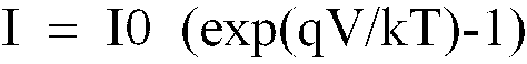
where
I is the external current flow,
I0 is the reverse saturation current,
q is the fundamental electronic charge of 1.602 x 10⁻¹⁹ coulombs,
V is the applied voltage,
k is the Boltzmann constant, and
T is the absolute temperature.
[0070] Under large negative applied voltage (reverse bias), the exponential term becomes
negligible compared to 1.0, and I is approximately -I0. I0 is strongly dependent on
the temperature of the junction and hence on the intrinsic-carrier concentration.
I0 is larger for materials with smaller bandgaps than for those with larger bandgaps.
The rectifier action of the diode -- that is, its restriction of current flow to only
one direction -- is in this particular embodiment the key to the operation of the
p-n junction element 58.
[0071] An alternative way to design a p-n junction element is to deposit a thin layer of
semiconductor onto a supporting material which does not absorb the kind of energy
utilized in the respective embodiments. For use with wirelessly transmitted energy
in terms of light waves, glass could be a suitable material. Various materials may
be used in the semiconductor layers such as but not limited to cadmium telluride,
copper-indium-diselenide and silicon. It is also possible to use a multilayer structure
with several layers of p and n-type materials to improve efficiency.
[0072] The electric energy generated by the p-n junction element 58 could be of the same
type as generated by solar cells, in which the negative and positive fields create
a direct current. Alternatively, the negative and positive semiconductor layers may
change polarity following the transmitted waves, thereby generating an alternating
current.
[0073] The p-n junction element 58 is designed to make it suited for implantation. Thus,
all the external surfaces of the element 58 in contact with the human body are made
of a biocompatible material. The p-n junction semiconductors are designed to operate
optimally at a body temperature of 37°C because the current output, which should be
more than 1 µA, is significantly depending on temperature as shown above. Since both
the skin and subcutis absorb energy, the relation between the sensitivity or working
area of the element 58 and the intensity or strength of the wireless energy transmission
is considered. The p-n junction element 58 preferably is designed flat and small.
Alternatively, if the element 58 is made in larger sizes it should be flexible, in
order to adapt to the patient's body movements. The volume of the element 58 should
be kept less than 2000 cm
3.
[0074] FIGURE 15 generally illustrates how any of the above-described embodiments of the
anal incontinence treatment apparatus of the invention may be implanted in a patient.
Thus, a restriction device 4 implanted in a patient engages the colon 66 to form an
artificial sphincter around the fecal passageway in the colon. An implanted operation
device 68, which may also be referred to as an adjustment device, such as an electric
motor or a motor/pump assembly, operates the restriction device 4 through a transmission
member 70, such as a mechanical transmission cord or a fluid tube. An energy transforming
means in the form of an element 6 having a positive region and a negative region,
as described above in more detail, is placed underneath the skin of the patient.
[0075] Wireless energy carried by a signal transmitted by a wireless remote control of an
external energy transmission means 10 at least partly penetrates the patient's skin
and hits the element 6. The energy thus hitting the element 6 is transformed into
energy of a different form that is suited for powering the operation device 68. For
example, where the operation device 68 is an electric motor the element 6 comprises
an electric p-n junction element that transforms the wireless energy into an electric
current for powering the electric motor. Where the operation device 68 comprises a
pump, the element 6 may transform the wireless energy into kinetic energy for powering
the pump.
[0076] The transformed energy may be utilized for directly operating the restriction device
4 or, where the restriction device 4 is electrically operated, for storage in a capacitor
and/or an accumulator for later or parallel use. Preferably (but not necessarily)
the element 6 is controlled by a microprocessor. The wireless remote control of the
external energy transmission means 10 is used to control the utilization of the transmitted
energy and any function or command to/from the implanted restriction device 4.
1. An anal incontinence treatment apparatus, comprising an energy transmission means
(10) for wireless transmission of energy of a first form from outside a patient's
body, an operable restriction device (4) implantable in a patient for engaging the
colon or rectum (66) to form a restricted faecal passageway in the colon or rectum,
the restriction device operable in response to energy of a second form different than
the energy of the first form to vary the restricted passageway, and an energy transforming
means (6) implantable in the patient for transforming energy of the first form wirelessly
transmitted by the energy transmission means into energy of the second form, which
is used for the operation of the restriction device, characterised in that the energy transforming means (6) comprises at least one element (58) having a positive
region (60) and a negative region (62), when exposed to the energy of the first form
transmitted by the energy transmission means (10), and is adapted to create an energy
field between the positive and negative regions (60,62), so that the energy field
produces the energy of the second form.
2. An apparatus according to claim 1, wherein the element comprises an electrical junction
element (58), and the electrical junction element is capable of inducing an electric
field between the positive and negative regions (60,62) when exposed to the energy
of the first form transmitted by the energy transmission means (10), whereby the energy
of the second form comprises electric energy.
3. An apparatus according to claim 2, wherein the restriction device (4) is electrically
operated, and the positive and negative regions (60,62) of the electrical junction
element (58) supply electric energy for the operation of the restriction device (4).
4. An apparatus according to claim 3, further comprising electric conductors connected
to the positive and negative regions of the electrical junction element (58), whereby
the electrical junction element is capable of supplying an electric current via the
conductors.
5. An apparatus according to claim 4, wherein the electrical junction element (58) is
capable of supplying a direct current or pulsating direct current via the conductors.
6. An apparatus according to claim 4, wherein the electrical junction element (58) is
capable of supplying an alternating current or a combination of a direct and alternating
current via the conductors.
7. An apparatus according to claim 3, wherein the electrical junction element (58) is
capable of supplying a frequency or amplitude modulated signal.
8. An apparatus according to claim 3, wherein the electrical junction element (58) is
capable of supplying an analog or digital signal.
9. An apparatus according to claim 1, further comprising an implantable operation device
(68) for operating the restriction device (4), wherein the element (58) powers the
operation device with the energy of the second form.
10. An apparatus according to claim 9, wherein the operation device (68) comprises a motor.
11. An apparatus according to claim 10, further comprising a control device, wherein the
motor (15,18,32,128) comprises a rotary motor, and the control device (36) controls
the rotary motor to rotate a desired number of revolutions.
12. An apparatus according to claim 10, wherein the motor (15,18,32,128) comprises a linear
motor.
13. An apparatus according to claim 10, further comprising a control device, wherein the
motor (15,18,32,128) comprises a hydraulic or pneumatic fluid motor, and the control
device (36) controls the fluid motor.
14. An apparatus according to claim 10, wherein the motor (15,18,32,128) comprises an
electric motor having electrically conductive parts made of plastics.
15. An apparatus according to claim 9, wherein the restriction device (4) comprises hydraulic
means and the operation device comprises a pump (15,18,32,128) for pumping a fluid
in the hydraulic means.
16. An apparatus according to claim 15, wherein the operation device (68) comprises a
motor for driving the pump.
17. An apparatus according to claim 15, wherein the operation device (68) comprises a
fluid conduit between the pump and the hydraulic means of the restriction device (4),
and a reservoir (20,30) for fluid, the reservoir forming part of the conduit.
18. An apparatus according to claim 17, wherein the hydraulic means, pump and conduit
are devoid of any non-return valve.
19. An apparatus according to claim 18, wherein the reservoir (20,30) forms a fluid chamber
with a variable volume, and the pump is adapted to distribute fluid from the chamber
to the hydraulic means of the restriction device by reduction of the volume of the
chamber and to withdraw fluid from the hydraulic means to the chamber by expansion
of the volume of the chamber.
20. An apparatus according to claim 9, further comprising a control device (36) for controlling
the operation device (68).
21. An apparatus according to claim 20, wherein the control device (36) is adapted to
shift polarity of the energy of the second form to reverse the operation device (68).
22. An apparatus according to claim 21, wherein the operation device (68) comprises an
electric motor and the energy of the second form comprises electric energy.
23. An apparatus according to claim 20, wherein the restriction device (4) is operable
to perform a reversible function.
24. An apparatus according to claim 23, further comprising a reversing device implantable
in the patient for reversing the function performed by the restriction device (4).
25. An apparatus according to claim 24, wherein the control device (36) controls the reversing
device to reverse the function performed by the restriction device (4).
26. An apparatus according to claim 24, wherein the reversing device comprises hydraulic
means including a valve for shifting the flow direction of a fluid flow in the hydraulic
means.
27. An apparatus according to claim 24, wherein the reversing device comprises a mechanical
reversing device.
28. An apparatus according to claim 27, wherein the reversing device comprises a gearbox
(54).
29. An apparatus according to claim 24, wherein the reversing device comprises a switch
(52).
30. An apparatus according to claim 29, wherein the switch (52) is operable by the energy
of the second form.
31. An apparatus according to claim 30, wherein the control device (36) controls the operation
of the switch (52) by shifting polarity of the energy of the second form.
32. An apparatus according to claim 30, wherein the switch (52) comprises an electric
switch and the energy of the second form comprises electric energy.
33. An apparatus according to claim 1, wherein the element (58) forms a flat and thin
sheet, and has a volume of less than 2000 cm3.
34. An apparatus according to claim 2, wherein the electrical junction element (58) comprises
at least one semiconductor.
35. An apparatus according to claim 2, wherein the electrical junction element (58) generates
an output current exceeding 1 µA when exposed to the energy of the first form transmitted
by the energy transmission means (10).
36. An apparatus according to claim 1, further comprising an energy storage device implantable
in the patient for storing the energy of the second form and for supplying energy
in connection with the operation of the restriction device (4).
37. An apparatus according to claim 36, wherein the energy storage device comprises an
accumulator (38).
38. An apparatus according to claim 37, wherein the energy of the second form comprises
electric energy and the energy storage device comprises an electric accumulator (38).
39. An apparatus according to claim 38, wherein the electric accumulator (38) comprises
at least one capacitor or at least one rechargeable battery, or a combination of at
least one capacitor and at least one rechargeable battery.
40. An apparatus according to claim 36, further comprising a switch (52) implantable in
the patient for directly or indirectly switching the operation of the restriction
device (4).
41. An apparatus according to claim 40, further comprising a source of energy implantable
in the patient, wherein the switch (52) is operated by the energy of the second form
supplied by the energy storage device to switch from an off mode, in which the source
of energy is not in use, to an on mode, in which the source of energy supplies energy
for the operation of the restriction device (4).
42. An apparatus according to claim 40, further comprising a source of energy implantable
in the patient, and a remote control (136) for controlling the supply of energy of
the source of energy, wherein the switch (52) is operated by the energy of the second
form supplied by the energy storage device to switch from an off mode, in which the
remote control is prevented from controlling the source of energy and the source of
energy is not in use, to a standby mode, in which the remote control is permitted
to control the source of energy to supply energy for the operation of the restriction
device.
43. An apparatus according to claim 1, further comprising a switch (52) implantable in
the patient for switching the operation of the restriction device (4).
44. An apparatus according to claim 3, further comprising a source of energy implantable
in the patient for supplying energy for the operation of the restriction device (4),
wherein the switch (52) is operated by the energy of the second form supplied by the
energy transforming means (10) to switch from an off mode, in which the source of
energy is not in use, to an on mode, in which the source of energy supplies energy
for the operation of the restriction device (4).
45. An apparatus according to claim 43, further comprising a source of energy implantable
in the patient for supplying energy for the operation of the restriction device (4),
and a remote control (136) for controlling the supply of energy of the source of energy,
wherein the switch (52) is operated by the energy of the second form supplied by the
energy transforming means (6) to switch from an off mode, in which the remote control
is prevented from controlling the source of energy and the source of energy is not
in use, to a standby mode, in which the remote control is permitted to control the
source of energy to supply energy for the operation of the restriction device (4).
46. An apparatus according to claim 1, wherein the energy transmission means (10) transmits
the energy of the first form by at least one wireless signal.
47. An apparatus according to claim 46, wherein the signal comprises a wave signal.
48. An apparatus according to claim 46, wherein the signal contains radiant energy.
49. An apparatus according to claim 47, wherein the wave signal comprises an electromagnetic
wave signal including one of an infrared light signal, a visible light signal, an
ultra violet light signal, a laser signal, a micro wave signal, a radio wave signal,
an x-ray radiation signal, and a gamma radiation signal.
50. An apparatus according to claim 47, wherein the wave signal comprises a sound wave
signal.
51. An apparatus according to claim 46, wherein the signal comprises a digital or analog
signal, or a combination of a digital and analog signal.
52. An apparatus according to claim 1, wherein the energy of the first form transmitted
by the energy transmission means (10) comprises an electric field.
53. An apparatus according to claim 52, wherein the electric field is transmitted in pulses
or digital pulses by the energy transmission means (10).
54. An apparatus according to claim 1, wherein the energy of the first form transmitted
by the energy transmission means (10) comprises a magnetic field.
55. An apparatus according to claim 54, wherein the magnetic field is transmitted in pulses
or digital pulses by the energy transmission means (10).
56. An apparatus according to claim 1, wherein the energy of the first form comprises
polarized energy.
57. An apparatus according to claim 1, wherein the energy transforming means (6) transforms
the energy of the first form into a direct current or pulsating direct current, or
a combination of a direct current and a pulsating direct current.
58. An apparatus according to claim 1, wherein the energy transforming means (6) transforms
the energy of the first form into an alternating current or a combination of a direct
and alternating current.
59. An apparatus according to claim 1, wherein the energy of the second form comprises
a frequency or amplitude modulated signal, or a combination of a frequency and amplitude
modulated signal.
60. An apparatus according to claim 1, wherein the energy of the second form comprises
an analog or a digital signal, or a combination of an analog and digital signal.
61. An apparatus according to claim 1, further comprising an implantable pulse generator
for generating electrical pulses from the energy of the second form produced by the
energy field.
62. An apparatus according to claim 1, further comprising at least one implantable sensor
(56) for sensing at least one physical parameter of the patient.
63. An apparatus according to claim 62, wherein the sensor (56) comprises a pressure sensor
for directly or indirectly sensing the pressure in the faecal passageway.
64. An apparatus according to claim 62, further comprising a control device (36) for controlling
the restriction device in response to signals from the sensor.
65. An apparatus according to claim 64, wherein the control device (36) comprises an internal
control unit implantable in the patient for controlling the restriction device (4)
in response to signals from the sensor (56).
66. An apparatus according to claim 64, wherein the internal control unit (36) directly
controls the restriction device (4) in response to signals from the sensor (56).
67. An apparatus according to claim 64 wherein the control device comprises an external
control unit (136) outside the patient's body for controlling the restriction device
(4) in response to signals from the sensor (56).
68. An apparatus according to claim 67, wherein the external control unit (136) stores
information on the physical parameter sensed by the sensor (56) and is manually operated
to control the restriction device based on the stored information.
69. An apparatus according to claim 62, further comprising at least one implantable sender
for sending information on the physical parameter sensed by the sensor (56).
70. An apparatus according to claim 9, wherein the operation device (68) comprises hydraulic
means and at least one valve for controlling a fluid flow in the hydraulic means.
71. An apparatus according to claim 70, further comprising a wireless remote control (136)
for controlling the valve.
72. An apparatus according to claim 1, further comprising a wireless remote control (136)
transmitting at least one wireless control signal for controlling the restriction
device (4).
73. An apparatus according to claim 72, wherein the remote control (136) is capable of
obtaining information on the condition of the restriction device (4) and to control
the restriction device in response to the information.
74. An apparatus according to claim 72, wherein the remote control comprises an implantable
control unit (38) for controlling the restriction device (4).
75. An apparatus according to claim 74, wherein the control unit comprises a microprocessor
(146).
76. An apparatus according to claim 72, wherein the wireless remote control comprises
at least one external signal transmitter or tranceiver (132) and at least one internal
signal receiver or transceiver (134) implantable in the patient.
77. An apparatus according to claim 72, wherein the wireless remote control comprises
at least one external signal receiver or transceiver (132) and at least one internal
signal transmitter or transceiver (134) implantable in the patient.
78. An apparatus according to claim 72, wherein the remote control is capable of sending
information related to the restriction device (4) from inside the patient's body to
the outside thereof.
79. An apparatus according to claim 78, wherein the remote control controls the restriction
device (4) in response to the information.
80. An apparatus according to claim 72, wherein the remote control comprises a control
signal transmitter for transmitting the control signal, and the energy transmission
means comprises the control signal transmitter, whereby the energy of the first form
is transmitted by the control signal.
81. An apparatus according to claim 72, wherein the energy transmission means (10) transmits
the energy of the first form by at least one signal separate from the control signal.
82. An apparatus according to claim 72, wherein the remote control transmits a carrier
signal for carrying the control signal.
83. An apparatus according to claim 72, wherein the energy transmission means (10) transmits
the energy of the first form by at least one signal, which is used as a carrier signal
for the control signal transmitted by the remote control.
84. An apparatus according to claim 83, wherein the carrier signal is frequency or amplitude
modulated, or frequency and amplitude modulated.
85. An apparatus according to claim 83, wherein the carrier signal comprises digital or
analog waves, or a combination of digital and analog waves.
86. An apparatus according to claim 83, wherein the control signal used with the carrier
signal is frequency or amplitude modulated, or frequency and amplitude modulated.
87. An apparatus according to claim 83, wherein the control signal used with the carrier
signal is digital or analog, or digital and analog.
88. An apparatus according to claim 72, wherein the control signal comprises a wave signal
comprising one of a sound wave signal including an ultrasound wave signal, an electromagnetic
wave signal including an infrared light signal, a visible light signal, an ultra violet
light signal and a laser light signal, a micro wave signal, a radio wave signal, an
x-ray radiation signal, and a gamma radiation signal.
89. An apparatus according to claim 72, wherein the control signal comprises an electric
or magnetic field, or an electric and magnetic field.
90. An apparatus according to claim 72, wherein the control signal comprises a digital
or analog control signal, or a digital and analog control signal.
91. An apparatus according to claim 90, wherein the remote control transmits an electromagnetic
carrier wave signal for carrying the digital or analog control signal.
92. An apparatus according to claim 1, wherein the energy of the second form used for
operating the restriction device is wirelessly transmitted by the energy transforming
means (6).
93. An apparatus according to claim 1, further comprising an implantable control unit
(36) for controlling the restriction device (4).
94. An apparatus according to claim 93, wherein the control unit (36) is programmable
for controlling the restriction device (4) in accordance with a program.
95. An apparatus according to claim 94, wherein the control unit (136) controls the restriction
device over time in accordance with an activity schedule program
96. An apparatus according to claim 94, further comprising an external wireless remote
control (138) for programming the implantable control unit (136).
97. An apparatus according to claim 1, further comprising an external data communicator
and an implantable internal data communicator communicating with the external data
communicator, wherein the internal data communicator feeds data related to the restriction
device back to the external data communicator or the external data communicator feeds
data to the internal data communicator.
98. An apparatus according to claim 97, wherein the internal data communicator feeds data
related to at least one physical signal of the patient.
99. An apparatus according to claim 1, wherein the restriction device (4) controls the
cross-sectional area of the restricted faecal passageway.
100. An apparatus according to claim 1, wherein the restriction device (4) is non-inflatable.
101. An apparatus according to claim 1, wherein the restriction device (4) is directly
operated with the energy of the second form, as the energy transmission means transmits
the energy of the first form.
102. An apparatus according to claim 101, wherein the restriction device (4) is directly
operated with the energy of the second form in a non-magnetic manner.
103. An apparatus according to claim 101, wherein the restriction device (4) is directly
operated with the energy of the second form without externally touching subcutaneously
implantable components of the apparatus.
104. An apparatus according to claim 1, wherein the energy of the first form comprises
kinetic energy.
105. An apparatus according to claim 1, wherein the energy transforming means (6) is implantable
subcutaneously or in the abdomen of the patient.
106. An apparatus according to claim 1, wherein the energy transforming means (6) is implantable
in the retroperitoneal space, abdomen, scrotum or labia majora, or implantable subcutaneously.
107. An apparatus according to claim 1, wherein the energy transforming means (6) is implantable
in an orifice of the patient's body and under the mucosa or intraluminar outside the
mucosa of the orifice.
108. An apparatus according to claim 1, wherein the element (58) comprises at least one
semiconductor circuitry creating the energy field when exposed to the energy of the
first form wirelessly transmitted by the energy transmission means (10).
109. An apparatus according to claim 1, wherein the element (58) comprises at least one
transistor circuitry creating the energy field when exposed to the energy of the first
form wirelessly transmitted by the energy transmission means (10).
110. An apparatus according to claim 1, wherein the element (58) comprises at least one
microchip creating the energy field when exposed to the energy of the first form wirelessly
transmitted by the energy transmission means (10).
1. Einrichtung zur Behandlung von analer Inkontinenz, das eine Energieübertragungsvonichtung
(10) zur drahtlosen Übertragung von Energie in einer ersten Form von außerhalb des
Körpers eines Patienten, eine in einen Patienten implantierbare betreibbare Sperrvorrichtung
(4), welche mit dem Dickdarm oder Rektum (66) im Eingriff steht, um einen abgesperrten
Fäkaldurchgang in dem Dickdarm oder Rektum zu bilden , wobei die Sperrvorrichtung
antreibbar ist als Antwort auf eine Energie in einer zweiten Form, die sich von der
Energie in der ersten Form unterscheidet, um den gesperrten Durchgang zu verändem
und eine in den Patienten implantierbare Energieübertragungsvorrichtung (6) zur Umwandlung
der Energie in der ersten Form, welche drahtlos durch die Energieumwandlungseinrichtung
übertragen wird in eine Energie in der zweiten Form, welche für den Betrieb der Sperrvorrichtung
verwendet wird umfasst, dadurch gekennzeichnet, dass die Energieumwandlungseinrichtung (6) zumindest ein Element (58) mit einem positiven
Gebiet (60) und einem negativen Gebiet (62) umfasst, wenn sie der Energie in der ersten
Form ausgesetzt wird, welche durch die Energieübertragungsvorrichtung (10) übertragen
wird und, dass es angepasst ist, um ein Energiefeld zwischen den positiven und negativen
Gebieten (60, 62) zu erzeugen, so dass das Energiefeld Energie der zweiten Form erzeugt.
2. Einrichtung nach Anspruch 1, wobei das Element ein elektrisches Sperrschichtelement
(58) umfasst und das elektrische Sperrschichtelement in der Lage ist, ein elektrisches
Feld zwischen den positiven und negativen Gebieten (60, 62) zu induzieren, wenn es
der Energie in der ersten Form ausgesetzt wird, welche durch die Energieübertragungsvorrichtung
(10) übertragen wird, wobei die Energie in der zweiten Form elektrische Energie umfasst.
3. Einrichtung nach Anspruch 2, wobei die Sperrvorrichtung (4) elektrisch betrieben wird
und die positiven und negativen Gebiete (60, 62) des elektrischen Sperrschichtelements
(58) elektrische Energie für den Betrieb der Sperrvorrichtung (4) liefern.
4. Einrichtung nach Anspruch 3, die ferner elektrische Leiter umfasst, welche mit den
positiven und negativen Gebieten des elektrischen Sperrschichtelements (58) verbunden
sind, wodurch das elektrische Sperrschichtelement in der Lage ist, einen elektrischen
Strom über die Leiter zu liefern.
5. Einrichtung nach Anspruch 4, wobei das elektrische Sperrschichtelement (58) in der
Lage ist, einen Gleichstrom oder einen pulsierenden Gleichstrom über die Leiter zu
liefern.
6. Einrichtung nach Anspruch 4, wobei das elektrische Sperrschichtelement (58) in der
Lage ist, einen Wechselstrom oder eine Kombination eines Gleich- und Wechselstroms
über die Leiter zu liefern.
7. Einrichtung nach Anspruch 3, wobei das elektrische Sperrschichtelement (58) in der
Lage ist, ein frequenz- oder amplitudenmoduliertes Signal zu liefern.
8. Einrichtung nach Anspruch 3, wobei das elektrische Sperrschichtelement (58) in der
Lage ist, ein analoges oder digitales Signal zu liefern.
9. Einrichtung nach Anspruch 1, das ferner eine implantierbare Betriebsvorrichtung (68)
zum Betrieb der Spemrorrichtung (4) umfasst, wobei das Element (58) die Betriebsvorrichtung
mit der Energie in der zweiten Form mit Strom versorgt.
10. Einrichtung nach Anspruch 9, wobei die Betriebsvorrichtung (68) einen Motor umfasst.
11. Einrichtung nach Anspruch 10, die ferner eine Steuerungsvorrichtung umfasst, wobei
der Motor (15, 18, 32, 128) einen Rotationsmotor umfasst und die Steuerungsvorrichtung
(36) den Rotationsmotor steuert, dass er sich mit einer erwünschten Anzahl an Umdrehungen
dreht.
12. Einrichtung nach Anspruch 10, wobei der Motor (15, 18, 32, 128) einen Linearmotor
umfasst.
13. Einrichtung nach Anspruch 10, die ferner eine Steuerungsvomichtung umfasst, wobei
der Motor (15, 18, 32, 128) einen hydraulischen oder pneumatischen Fluidmotor umfasst
und die Steuerungsvorrichtung (36) den Fluidmotor steuert.
14. Einrichtung nach Anspruch 10, wobei der Motor (15, 18, 32, 128) einen Elektromotor
mit elektrisch leitfähigen Teilen aus Kunststoff umfasst.
15. Einrichtung nach Anspruch 9, wobei die Sperrvorrichtung (4) eine hydraulische Einrichtung
umfasst und die Betriebsvorrichtung eine Pumpe (15, 18, 32, 128) zum Pumpen einer
Flüssigkeit in der hydraulischen Einrichtung umfasst.
16. Einrichtung nach Anspruch 15, wobei die Betriebsvorrichtung (68) einen Motor zum Antrieb
der Pumpe umfasst.
17. Einrichtung nach Anspruch 15, wobei die Betriebsvorrichtung (68) einen Flüssigkeitskanal
zwischen der Pumpe und der hydraulischen Einrichtung der Sperrvorrichtung (4) und
einen Vorratsbehälter (20, 30) für Flüssigkeit umfasst, wobei der Vorratsbehälter
einen Teil des Kanals bildet.
18. Einrichtung nach Anspruch 17, wobei die hydraulische Einrichtung, die Pumpe und der
Kanal frei sind von jeglichem Rückschlagventil.
19. Einrichtung nach Anspruch 18, wobei der Vorratsbehälter (20, 30) eine Flüssigkeitskammer
mit einem variablen Volumen bildet und die Pumpe angepasst ist, um Flüssigkeit von
der Kammer zu der hydraulischen Einrichtung der Sperrvorrichtung durch Reduktion des
Volumens der Kammer zu verteilen und Flüssigkeit von der hydraulischen Einrichtung
zu der Kammer durch Expansion des Volumens der Kammer zurückzuziehen.
20. Einrichtung nach Anspruch 9, die ferner eine Steuerungsvorrichtung (36) zur Steuerung
der Betriebsvorrichtung (68) umfasst.
21. Einrichtung nach Anspruch 20, wobei die Steuerungsvorrichtung (36) eingerichtet ist,
die Polarität der Energie in der zweiten Form zu verschieben, um die Betriebsvorrichtung
(68) umzukehren.
22. Einrichtung nach Anspruch 21, wobei die Betriebsvorrichtung (68) einen elektrischen
Motor umfasst und die Energie in der zweiten Form elektrische Energie umfasst.
23. Einrichtung nach Anspruch 20, wobei die Sperrvorrichtung (4) betreibbar ist, um eine
reversible Funktion auszuführen.
24. Einrichtung nach Anspruch 23, die ferner eine Umkehrvorrichtung umfasst, die in den
Patienten implantierbar ist, um die Funktion, welche durch die Sperrvorrichtung (4)
ausgeführt wird umzukehren.
25. Einrichtung nach Anspruch 24, wobei die Steuerungsvorrichtung (36) die Umkehrvorrichtung
steuert, um die Funktion, welche durch die Sperrvorrichtung (4) ausgeführt wird umzukehren.
26. Einrichtung nach Anspruch 24, wobei die Umkehrvorrichtung eine hydraulische Einrichtung
einschließlich eines Ventils zur Verschiebung der Flussrichtung eines Flüssigkeitsstroms
in der hydraulischen Einrichtung umfasst.
27. Einrichtung nach Anspruch 24, wobei die Umkehrvorrichtung eine mechanische Umkehrvorrichtung
umfasst.
28. Einrichtung nach Anspruch 27, wobei die Umkehrvorrichtung ein Rädergetriebe (54) umfasst.
29. Einrichtung nach Anspruch 24, wobei die Umkehrvorrichtung einen Schalter (52) umfasst.
30. Einrichtung nach Anspruch 29, wobei der Schalter (52) schaltbar ist durch die Energie
in der zweiten Form.
31. Einrichtung nach Anspruch 30, wobei die Steuerungsvorrichtung (36) den Betrieb des
Schalters (52) steuert durch Verschieben von Polarität der Energie in der zweiten
Form.
32. Einrichtung nach Anspruch 30, wobei der Schalter (52) einen elektrischen Schalter
umfasst und die Energie in der zweiten Form elektrische Energie umfasst.
33. Einrichtung nach Anspruch 1, wobei das Element (58) eine flache und dünne Platte ausbildet
und ein Volumen von weniger als 2000 cm3 besitzt.
34. Einrichtung nach Anspruch 2, wobei das elektrische Sperrschichtelement (58) zumindest
einen Halbleiter umfasst.
35. Einrichtung nach Anspruch 2, wobei das elektrische Sperrschichtelement (58) einen
Ausgangsstrom über 1 µA erzeugt, wenn es der Energie in der ersten Form ausgesetzt
wird, welche durch die Energieübertragungseinrichtung (10) übertragen wird.
36. Einrichtung nach Anspruch 1, die ferner eine Energiespeichervorrichtung umfasst, welche
in den Patienten imptantierbar ist, um die Energie in der zweiten Form zu speichem
und Energie im Zusammenhang mit dem Betrieb der Sperrvorrichtung (4) zu liefern.
37. Einrichtung nach Anspruch 36, wobei die Energiespeichervorrichtung einen Akku (38)
umfasst.
38. Einrichtung nach Anspruch 37, wobei die Energie in der zweiten Form elektrische Energie
umfasst und die Energiespeichervorrichtung einen elektrischen Akku (38) umfasst.
39. Einrichtung nach Anspruch 38, wobei der elektrische Akku (38) zumindest einen Kondensator
oder zumindest eine wiederaufladbare Batterie oder eine Kombination von zumindest
einem Kondensator und zumindest einer wiederaufladbaren Batterie umfasst.
40. Einrichtung nach Anspruch 36, die ferner einen Schalter (52), der in den Patienten
implantierbar ist umfasst, zum direkten oder indirekten Schalten des Betriebs der
Sperrvorrichtung (4).
41. Einrichtung nach Anspruch 40, die ferner eine in den Patienten implantierbare Energiequelle
umfasst, wobei der Schalter (52) durch die Energie in der zweiten Form betrieben wird,
welche durch die Energiespeichervorrichtung geliefert wird, um von einem Aus-Zustand,
in welchem die Energiequelle nicht verwendet wird zu einem An-Zustand zu schalten,
in welchem die Energiequelleenergie Energie für den Betrieb der Sperrvorrichtung (4)
liefert.
42. Einrichtung nach Anspruch 40, die ferner eine in den Patienten implantierbare Energiequelle
umfasst und eine Fembedienung (136) zur Steuerung der Energiezufuhr von der Energiequelle,
wobei der Schalter (52) durch die Energie in der zweiten Form betrieben wird, welche
durch die Energiespeichervorrichtung geliefert wird, um von einem Aus-Zustand, in
welchem die Fernbedienung gehindert wird die Energiequelle zu steuern und die Energiequelle
nicht verwendet wird zu einem Bereitschaftsmodus umzuschalten, bei dem es der Fernbedienung
erlaubt ist die Energiequelle zu steuem, um Energie für den Betrieb der Sperrvorrichtung
zu liefern.
43. Einrichtung nach Anspruch 1, die ferner einen in den Patienten implantierbaren Schalter
(52) zum Schalten des Betriebs der Sperrvorrichtung (4) umfasst.
44. Einrichtung nach Anspruch 3, die ferner eine in den Patienten implantierbare Energiequelle
umfasst zur Lieferung von Energie für den Betrieb der Sperrvorrichtung (4), wobei
der Schalter (52) durch die Energie in der zweiten Form betrieben wird, welche durch
die Energieumwandlungseinrichtung (10) geliefert wird, um von einem Aus-Zustand, in
welchem die Energiequelle nicht verwendet wird zu einem An-Zustand zu schalten, in
welchem die Energiequelleenergie Energie für den Betrieb der Sperrvorrichtung (4)
liefert.
45. Einrichtung nach Anspruch 43, die ferner eine in den Patienten implantierbare Energiequelle
umfasst zur Lieferung von Energie für den Betrieb der Sperrvorrichtung (4) und eine
Fembedienung (136) zur Steuerung der Energiezufuhr von der Energiequelle, wobei der
Schalter (52) durch die Energie in der zweiten Form betrieben wird, welche durch die
Energieumwandlungsvorrichtung (6) geliefert wird, um von einem Aus-Zustand, in welchem
die Fernbedienung gehindert wird die Energiequelle zu steuern und die Energiequelle
nicht verwendet wird zu einem Bereitschaftsmodus umzuschalten, bei dem es der Fernbedienung
erlaubt ist die Energiequelle zu steuern, um Energie für den Betrieb der Sperrvorrichtung
(4) zu liefern.
46. Einrichtung nach Anspruch 1, wobei die Energieübertragungsvorrichtung (10) die Energie
in der ersten Form durch zumindest ein drahtloses Signal übertragt.
47. Einrichtung nach Anspruch 46, wobei das Signal ein Wellensignal umfasst.
48. Einrichtung nach Anspruch 46, wobei das Signal Strahlungsenergie enthält.
49. Einrichtung nach Anspruch 47, wobei das Wellensignal ein elektromagnetisches Wellensignal
umfasst, welches eines der folgenden Signale einschließt: ein Infrarotlicht-Signal,
ein Signal aus sichtbarem Licht, ein Ultraviolettlicht-Signal, ein Laser-Signal, ein
Mikrowellen-Signal, ein Radiowellen-Signal, ein Röntgenstrahlungs-Signal und ein Gammastrahlungs-Signal.
50. Einrichtung nach Anspruch 47, wobei das Wellensignal ein Schallwellensignal umfasst.
51. Einrichtung nach Anspruch 46, wobei das Signal ein digitales oder analoges Signal
oder eine Kombination eines digitalen und analogen Signals umfasst.
52. Einrichtung nach Anspruch 1, wobei die Energie in der ersten Form, die durch eine
Energieübertragungseinrichtung (10) übertragen wird, ein elektrisches Feld umfasst.
53. Einrichtung nach Anspruch 52, wobei das elektrische Feld in Pulsen oder digitalen
Pulsen durch die Energieübertragungseinrichtung (10) übertragen wird.
54. Einrichtung nach Anspruch 1, wobei die Energie in der ersten Form, die durch eine
Energieübertragungseinrichtung (10) übertragen wird, ein magnetisches Feld umfasst.
55. Einrichtung nach Anspruch 54, wobei das magnetische Feld in Pulsen oder digitalen
Pulsen durch die Energieübertragungseinrichtung (10) übertragen wird.
56. Einrichtung nach Anspruch 1, wobei die Energie in der ersten Form polarisierte Energie
umfasst.
57. Einrichtung nach Anspruch 1, wobei die Energieumwandlungseinrichtung (6) die Energie
in der ersten Form in einen Gleichstrom oder pulsierenden Gleichstrom oder eine Kombination
aus einem Gleichstrom und einem pulsierenden Gleichstrom umwandelt.
58. Einrichtung nach Anspruch 1, wobei die Energieumwandlungseinrichtung (6) die Energie
in der ersten Form in einen Wechselstrom oder eine Kombination aus einem Gleichstrom
und einem Wechselstrom umwandelt.
59. Einrichtung nach Anspruch 1, wobei die Energie in der zweiten Form ein frequenz- oder
amplitudenmoduliertes Signal oder eine Kombination eines frequenz- und amplitudenmodulierten
Signals umfasst.
60. Einrichtung nach Anspruch 1, wobei die Energie in der zweiten Form ein analoges oder
digitales Signal oder eine Kombination eines analogen und digitalen Signals umfasst.
61. Einrichtung nach Anspruch 1, die ferner einen implantierbaren Pulsgenerator zur Erzeugung
von elektrischem Pulsen aus der Energie in der zweiten Form umfasst, welche durch
das Energiefeld erzeugt werden.
62. Einrichtung nach Anspruch 1, die ferner zumindest einen implantierbaren Sensor (56)
zur Ermittlung von zumindest einem physikalischen Parameter des Patienten umfasst.
63. Einrichtung nach Anspruch 62, wobei der Sensor (56) einen Drucksensor zur direkten
oder indirekten Ermittlung des Drucks in dem Fäkaldurchgang umfasst.
64. Einrichtung nach Anspruch 62, die ferner eine Steuerungsvorrichtung (36) zur Steuerung
der Spenvorrichtung als Antwort auf Signale von dem Sensor umfasst.
65. Einrichtung nach Anspruch 64, wobei die Steuerungsvorrichtung (36) eine in den Patienten
implantierbare interne Steuerungseinheit umfasst, zur Steuerung der Sperrvorrichtung
(4) als Antwort auf Signale von dem Sensor (56).
66. Einrichtung nach Anspruch 64, wobei die interne Steuerungseinheit (36) direkt die
Sperrvorrichtung (4) als Antwort auf Signale von dem Sensor (56) steuert.
67. Einrichtung nach Anspruch 64, wobei die Steuerungsvorrichtung eine externe Steuerungseinheit
(136) außerhalb des Körpers des Patienten umfasst zur Steuerung der Sperrvorrichtung
(4) als Antwort auf Signale von dem Sensor (56).
68. Einrichtung nach Anspruch 67, wobei die externe Steuerungseinheit (136) Information
bezüglich des physikalischen Parameters speichert, welche durch den Sensor (56) ermittelt
wird und manuell bedient wird, um die Sperrvorrichtung auf der Basis der gespeicherten
Informationen zu steuern.
69. Einrichtung nach Anspruch 62, die ferner zumindest einen implantierbaren Sender zum
Senden von Information bezüglich des physikalischen Parameters umfasst, der durch
den Sensor (56) ermittelt wird.
70. Einrichtung nach Anspruch 9, wobei die Betriebsvorrichtung (68) eine hydraulische
Einrichtung und zumindest ein Ventil zur Steuerung eines Flüssigkeitsstroms in der
hydraulischen Einrichtung umfasst.
71. Einrichtung nach Anspruch 70, die ferner eine drahtlose Fembedienung (136) zur Steuerung
des Ventils umfasst.
72. Einrichtung nach Anspruch 1, die ferner eine drahtlose Fernbedienung (136) zur Übertragung
von zumindest einem drahtlosen Steuerungssignal zur Steuerung der Sperrvorrichtung
(4) umfasst.
73. Einrichtung nach Anspruch 72, wobei die Fernbedienung (136) in der Lage ist, information
bezüglich des Zustandes der Sperrvorrichtung (4) zu erhalten und die Sperrvorrichtung
als Antwort auf die Information zu steuern.
74. Einrichtung nach Anspruch 72, wobei die Fernbedienung eine implantierbare Steuerungseinheit
(38) zur Steuerung der Sperrvorrichtung (4) umfasst.
75. Einrichtung nach Anspruch 74, wobei die Steuerungseinheit einen Mikroprozessor (146)
umfasst.
76. Einrichtung nach Anspruch 72, wobei die drahtlose Fernbedienung zumindest einen extemen
Signalsender oder Transceiver (132) und zumindest einen, in den Patienten implantierbaren
internen Signalempfänger oder Transceiver (134) umfasst.
77. Einrichtung nach Anspruch 72, wobei die drahtlose Fernbedienung zumindest einen extemen
Signalempfänger oder Transceiver (132) und zumindest einen, in den Patienten implantierbaren
internen Signalsender oder Transceiver (134) umfasst.
78. Einrichtung nach Anspruch 72, wobei die Fernbedienung in der Lage ist, Information
bezüglich der Sperrvorrichtung (4) von innerhalb des Körpers des Patienten zu dessen
Außenseite zu senden.
79. Einrichtung nach Anspruch 78, wobei die Fernbedienung die Sperrvorrichtung (4) als
Antwort auf die Information steuert.
80. Einrichtung nach Anspruch 72, wobei die Fernbedienung einen Steuerungssignalsender
zur Übertragung des Steuerungssignals umfasst und die Energieübertragungseinheit umfasst
den Steuerungssignalsender, wobei die Energie in der ersten Form durch das Steuerungssignal
übertragen wird.
81. Einrichtung nach Anspruch ein 72, wobei die Energieübertragungseinrichtung (10) die
Energie in der ersten Form überträgt durch zumindest ein Signal, das von dem Steuerungssignal
getrennt ist.
82. Einrichtung nach Anspruch 72, wobei die Fernbedienung ein Trägersignal zum Tragen
des Steuerungssignals überträgt.
83. Einrichtung nach Anspruch 72, wobei die Energieübertragungseinrichtung (10) die Energie
in der ersten Form durch zumindest ein Signal überträgt, welches als ein Trägersignal
für das Steuerungssignal verwendet wird, das durch die Fernbedienung übertragen wird.
84. Einrichtung nach Anspruch 83, wobei das Trägersignal frequenz- oder amplitudenmoduliert
oder frequenz- und amplitudenmoduliert ist.
85. Einrichtung nach Anspruch 83, wobei das Trägersignal digitale oder analoge Wellen
oder eine Kombination von digitalen und analogen Wellen umfasst.
86. Einrichtung nach Anspruch 83, wobei das Steuerungssignal, welches mit dem Trägersignat
verwendet wird frequenz- oder amplitudenmoduliert oder frequenz- und amplitudenmoduliert
ist.
87. Einrichtung nach Anspruch 83, wobei das Steuerungssignal, welches mit dem Trägersignal
verwendet wird digital oder analog oder digital und analog ist.
88. Einrichtung nach Anspruch 72, wobei das Steuerungssignal ein Wellensignal umfasst,
welches folgende Signale umfasst: ein Schallwellen-Signal einschließlich eines Ultraschallwellensignals,
ein elektromagnetisches Wellensignal einschließlich eines Infrarot-Lichtsignals, sichtbaren
Licht-Signals, ultravioletten Licht-Signals und Laserlicht-Signals, ein Mikrowellen-Signal,
ein Radiowellen-Signal, ein Röntgenstrahlungs-Signal und ein Gammastrahlungs-Signal.
89. Einrichtung nach Anspruch 72, wobei das Steuerungssignal ein elektrisches oder magnetisches
Feld oder ein elektrisches und magnetisches Feld umfasst.
90. Einrichtung nach Anspruch 72, wobei das Steuerungssignal ein digitales oder analoges
Steuerungssignal oder ein digitales und analoges Steuerungssignal umfasst.
91. Einrichtung nach Anspruch 90, wobei die Fernbedienung ein elektromagnetisches Träger-Wellensignal
zum Tragen des digitalen oder analogen Steuerungssignals überträgt.
92. Einrichtung nach Anspruch 1, wobei die Energie in der zweiten Form, die zum Betrieb
der Spenvorrichtung verwendet wird, drahtlos über die Energieumwandlungseinrichtung
(6) übertragen wird.
93. Einrichtung nach Anspruch 1, die ferner eine implantierbare Steuerungseinheit (36)
zur Steuerung der Sperrvorrichtung (4) umfasst.
94. Einrichtung nach Anspruch 93, wobei die Steuerungseinheit (36) programmierbar ist
zur Steuerung der Sperrvorrichtung (4) in Übereinstimmung mit einem Programm.
95. Einrichtung nach Anspruch 94, wobei die Steuerungseinheit (136) die Sperrvorrichtung
im Zeitablauf in Übereinstimmung mit einem Arbeitsablaufprogramm steuert.
96. Einrichtung nach Anspruch 94, die ferner eine externe drahtlose Fernbedienung (138)
zur Programmierung der implantierbaren Steuerungseinheit (136) umfasst.
97. Einrichtung nach Anspruch 1, die ferner einen extemen Datengeber und einen implantierbaren
internen Datengeber, der mit dem externen Datengeber kommuniziert umfasst, wobei der
interne Datengeber Daten, die mit der Sperrvorrichtung verknüpft sind zurück zu dem
extemen Datengeber führt oder der externe Datengeber Daten zu dem internen Datengeber
führt.
98. Einrichtung nach Anspruch 97, wobei der interne Datengeber Daten, die mit zumindest
einem physikalischen Signal des Patienten verknüpft sind zuführt.
99. Einrichtung nach Anspruch 1, wobei die Sperrvorrichtung (4) das Querschnittsgebiet
des gesperrten Fäkaldurchgangs steuert.
100. Einrichtung nach Anspruch 1, wobei die Sperrvorrichtung (4) nicht aufblasbar ist.
101. Einrichtung nach Anspruch 1, wobei die Spenvorrichtung (4) direkt mit der Energie
in der zweiten Form betrieben wird, während die Energieübertragungsseinrichtung die
Energie in der ersten Form überträgt.
102. Einrichtung nach Anspruch 101, wobei die Sperrvorrichtung (4) direkt mit der Energie
in der zweiten Form auf eine nicht magnetische Weise betrieben wird.
103. Einrichtung nach Anspruch 101, wobei die Sperrvorrichtung (4) direkt mit der Energie
in der zweiten Form ohne eine externe Berührung der subkutan implantierbaren Komponenten
der Einrichtung betrieben wird.
104. Einrichtung nach Anspruch 1, wobei die Energie in der ersten Form kinetische Energie
umfasst.
105. Einrichtung nach Anspruch 1, wobei die Energieumwandlungseinrichtung (6) subkutan
oder in den Bauchraum des Patienten implantierbar ist.
106. Einrichtung nach Anspruch 1, wobei die Energieumwandlungseinrichtung (6) in den retroperitonealen
Raum, den Bauchraum, das Skrotum oder die Labia majora, oder subkutan implantierbar
ist.
107. Einrichtung nach Anspruch 1, wobei die Energieumwandlungseinrichtung (6) in eine Öffnung
des Körpers des Patienten und unter die Mucosa oder intraluminar außerhalb der Mucosa
der Öffnung implantierbar ist.
108. Einrichtung nach Anspruch 1, wobei das Element (58) zumindest eine Halbleiterschaltung
umfasst, welche das Energiefeld erzeugt, wenn es der Energie in der ersten Form ausgesetzt
wird, welche drahtlos durch die Energieübertragungsseinrichtung (10) übertragen wird.
109. Einrichtung nach Anspruch 1, wobei das Element (58) zumindest eine Transistorschaltung
umfasst, welche das Energiefeld erzeugt, wenn es der Energie in der ersten Form ausgesetzt
wird, welche drahtlos durch die Energieübertragungsseinrichtung (10) übertragen wird.
110. Einrichtung nach Anspruch 1, wobei das Element (58) zumindest einen Mikrochip umfasst,
der das Energiefeld erzeugt, wenn er der Energie in der ersten Form ausgesetzt wird,
welche drahtlos durch die Energieübertragungsseinrichtung (10) übertragen wird.
1. Appareil de traitement d'incontinence anale, comprenant un dispositif (10) de transmission
d'énergie destiné à transmettre sans fil de l'énergie d'une première forme depuis
l'extérieur d'un corps de patient, un dispositif réglable (4) de restriction implantable
dans un patient afin qu'il coopère avec le côlon ou le rectum (66), le dispositif
de restriction étant réglable avec de l'énergie d'une seconde forme différente de
l'énergie de la première forme afin qu'il fasse varier le passage rétréci, et un dispositif
(6) de transformation d'énergie implantable dans le patient et destiné à transformer
l'énergie de la première forme transmise sans fil par le dispositif de transmission
d'énergie en énergie de la seconde forme, qui est utilisée pour la manoeuvre du dispositif
de restriction, caractérisé en ce que le dispositif (6) de transformation d'énergie comporte au moins un élément (58) ayant
une région positive (60) et une région négative (62), lorsqu'il est exposé à l'énergie
de la première forme transmise par le dispositif de transmission d'énergie (10), et
est destiné à créer un champ d'énergie entre les régions positive et négative (60,
62) afin que le champ d'énergie produise de l'énergie de la seconde forme.
2. Appareil selon la revendication 1, dans lequel l'élément comporte un élément (58)
à jonction électrique, et l'élément à jonction électrique est capable d'induire un
champ électrique entre les régions positive et négative (60, 62) lorsqu'il est exposé
à l'énergie de la première forme transmise par le dispositif (10) de transmission
d'énergie, et l'énergie de la seconde forme est de l'énergie électrique.
3. Appareil selon la revendication 2, dans lequel le dispositif de restriction (4) est
commandé électriquement, et les régions positive et négative (60, 62) de l'élément
à jonction électrique (58) transmettent de l'énergie électrique pour la commande du
dispositif de restriction (4).
4. Appareil selon la revendication 3, comprenant en outre des conducteurs électriques
connectés aux régions positive et négative de l'élément à jonction électrique (58)
et l'élément à jonction électrique est capable de transmettre un courant électrique
par l'intermédiaire des conducteurs.
5. Appareil selon la revendication 4, dans lequel l'élément à jonction électrique (58)
est capable de transmettre un courant continu ou un courant continu pulsé par les
conducteurs.
6. Appareil selon la revendication 4, dans lequel l'élément à jonction électrique (58)
est capable de transmettre un courant alternatif ou une combinaison d'un courant continu
et d'un courant alternatif par l'intermédiaire des conducteurs.
7. Appareil selon la revendication 3, dans lequel l'élément à jonction électrique (58)
est capable de transmettre un signal modulé en fréquence ou en amplitude.
8. Appareil selon la revendication 3, dans lequel l'élément à jonction électrique (58)
est capable de transmettre un signal analogique ou numérique.
9. Appareil selon la revendication 1, comprenant en outre un dispositif implantable de
manoeuvre (68) destiné à manoeuvrer le dispositif de restriction (4), et l'élément
(58) alimente le dispositif de manoeuvre en énergie de la seconde forme.
10. Appareil selon la revendication 9, dans lequel le dispositif de manoeuvre (68) comporte
un moteur.
11. Appareil selon la revendication 10, comprenant en outre un dispositif de commande
et dans lequel le moteur (15, 18, 32, 128) est un moteur rotatif et le dispositif
de commande (36) commande le moteur rotatif afin qu'il tourne un nombre voulu de tours.
12. Appareil selon la revendication 10, dans lequel le moteur (15, 18, 32, 128) est un
moteur linéaire.
13. Appareil selon la revendication 10, comprenant en outre un dispositif de commande,
et le moteur (15, 18, 32, 128) comprend un moteur à fluide hydraulique ou pneumatique
et le dispositif de commande (36) commande le moteur à fluide.
14. Appareil selon la revendication 10, dans lequel le moteur (15, 18, 32, 128) est un
moteur électrique ayant des parties conductrices de l'électricité formées de matière
plastique.
15. Appareil selon la revendication 9, dans lequel le dispositif de restriction (4) comporte
un dispositif hydraulique et le dispositif de manoeuvre comporte une pompe (15, 18,
32, 128) destinée à pomper un fluide dans le dispositif hydraulique.
16. Appareil selon la revendication 15, dans lequel le dispositif de manoeuvre (68) comporte
un moteur destiné à entraîner la pompe.
17. Appareil selon la revendication 15, dans lequel le dispositif de manoeuvre (68) comprend
un conduit de fluide placé entre la pompe et le dispositif hydraulique du dispositif
de restriction (4), et un réservoir (20, 30) de fluide, le réservoir faisant partie
du conduit.
18. Appareil selon la revendication 17, dans lequel le dispositif hydraulique, la pompe
et le conduit sont dépourvus de tout clapet de retenue.
19. Appareil selon la revendication 18, dans lequel le réservoir (20, 30) forme une chambre
de fluide de volume variable, et la pompe est destinée à distribuer du fluide de la
chambre vers le dispositif hydraulique du dispositif de restriction par réduction
du volume de la chambre et à évacuer du fluide du dispositif hydraulique vers la chambre
par dilatation du volume de la chambre.
20. Appareil selon la revendication 9, comprenant en outre un dispositif de commande (36)
destiné à commander le dispositif de manoeuvre (68).
21. Appareil selon la revendication 20, dans lequel le dispositif de commande (36) est
destiné à changer la polarité de l'énergie de la seconde forme pour inverser le dispositif
de manoeuvre (68).
22. Appareil selon la revendication 21, dans lequel le dispositif de manoeuvre (68) comporte
un moteur électrique et l'énergie de la seconde forme est de l'énergie électrique.
23. Appareil selon la revendication 20, dans lequel le dispositif de restriction (4) peut
être commandé afin qu'il exécute un fonctionnement réversible.
24. Appareil selon la revendication 23, comprenant en outre un dispositif d'inversion
implantable dans le patient et destiné à inverser le fonctionnement exécuté par le
dispositif de restriction (4).
25. Appareil selon la revendication 24, dans lequel le dispositif de commande (36) commande
le dispositif d'inversion afin qu'il inverse le fonctionnement exécuté par le dispositif
de restriction (4).
26. Appareil selon la revendication 24, dans lequel le dispositif d'inversion comprend
un dispositif hydraulique qui comporte une soupape destinée à changer le sens de circulation
du courant de fluide dans le dispositif hydraulique.
27. Appareil selon la revendication 24, dans lequel le dispositif d'inversion comporte
un dispositif mécanique d'inversion.
28. Appareil selon la revendication 27, dans lequel le dispositif d'inversion comprend
un réducteur (54).
29. Appareil selon la revendication 24, dans lequel le dispositif d'inversion comporte
un commutateur (52).
30. Appareil selon la revendication 29, dans lequel le commutateur (52) est réglable par
de l'énergie de la seconde forme.
31. Appareil selon la revendication 30, dans lequel le dispositif de commande (36) commande
le fonctionnement du commutateur (52) par changement de la polarité de l'énergie de
la seconde forme.
32. Appareil selon la revendication 30, dans lequel le commutateur (52) est un commutateur
électrique et l'énergie de la seconde forme est de l'énergie électrique.
33. Appareil selon la revendication 1, dans lequel l'élément (58) forme une feuille mince
et plate et a un volume inférieur à 2 000 cm3.
34. Appareil selon la revendication 1, dans lequel l'élément à jonction électrique (58)
comporte au moins un élément à semi-conducteur.
35. Appareil selon la revendication 2, dans lequel l'élément à jonction électrique (58)
crée un courant de sortie supérieur à 1 µA lorsqu'il est exposé à l'énergie de la
première forme transmise par le dispositif de transmission d'énergie (10).
36. Appareil selon la revendication 1, comprenant en outre un dispositif d'accumulation
d'énergie implantable dans le patient et destiné à accumuler l'énergie de la seconde
forme et à transmettre l'énergie en fonction de la manoeuvre du dispositif de restriction
(4).
37. Appareil selon la revendication 36, dans lequel le dispositif d'accumulation d'énergie
est un accumulateur électrique (38).
38. Appareil selon la revendication 37, dans lequel l'énergie de la seconde forme est
de l'énergie électrique et le dispositif d'accumulation d'énergie est un accumulateur
électrique (38).
39. Appareil selon la revendication 38, dans lequel l'accumulateur électrique (38) comporte
au moins un condensateur ou au moins un accumulateur rechargeable ou une combinaison
d'au moins un condensateur et d'au moins un accumulateur rechargeable.
40. Appareil selon la revendication 36, comprenant en outre un commutateur (52) implantable
dans le patient afin qu'il commute directement ou indirectement le fonctionnement
du dispositif de restriction (4).
41. Appareil selon la revendication 40, comprenant en outre une source d'énergie implantable
dans le patient, et dans lequel le commutateur (52) est commandé par l'énergie de
la seconde forme transmise par le dispositif d'accumulation d'énergie afin qu'il soit
commuté d'un mode d'ouverture dans lequel la source d'énergie n'est pas utilisée à
un mode de fermeture dans lequel la source d'énergie transmet de l'énergie pour la
manoeuvre du dispositif de restriction (4).
42. Appareil selon la revendication 40, comprenant en outre une source d'énergie implantable
dans le patient, et une commande à distance (136) destinée à commander la transmission
d'énergie de la source d'énergie, dans lequel le commutateur (52) est commandé par
l'énergie de la seconde forme transmise par le dispositif d'accumulation d'énergie
pour la commutation d'un mode d'ouverture, dans lequel la commande à distance ne peut
pas commander la source d'énergie et la source d'énergie n'est pas utilisée, à un
mode d'attente dans lequel la commande à distance peut commander la source d'énergie
pour la transmission d'énergie pour la manoeuvre du dispositif de restriction.
43. Appareil selon la revendication 1, comprenant en outre un commutateur (52) implantable
dans le patient et destiné à commuter le fonctionnement du dispositif de restriction
(4).
44. Appareil selon la revendication 3, comprenant en outre une source d'énergie implantable
dans le patient pour la transmission d'énergie pour la manoeuvre du dispositif de
restriction (4), dans lequel le commutateur (52) est commandé par l'énergie de la
seconde forme provenant du dispositif de transmission d'énergie (10) pour la commutation
d'un mode d'ouverture, dans lequel la source d'énergie n'est pas utilisée, à un mode
de fermeture dans lequel la source d'énergie transmet de l'énergie pour la manoeuvre
du dispositif de restriction (4).
45. Appareil selon la revendication 43, comprenant en outre une source d'énergie implantable
dans le patient pour la transmission d'énergie pour la manoeuvre du dispositif de
restriction (4), et une commande à distance (136) destinée à commander la transmission
d'énergie de la source d'énergie, dans lequel le commutateur (52) est commandé par
l'énergie de la seconde forme transmise par le dispositif de transformation d'énergie
(6) pour la commutation d'un mode d'ouverture, dans lequel la commande à distance
ne peut pas commander la source d'énergie et la source d'énergie n'est pas utilisée,
à un mode d'attente, dans lequel la commande à distance peut commander la source d'énergie
pour la transmission de l'énergie pour la manoeuvre du dispositif de restriction (4).
46. Appareil selon la revendication 1, dans lequel le dispositif (10) de transmission
d'énergie transmet de l'énergie de la première forme à l'aide d'au moins un signal
sans fil.
47. Appareil selon la revendication 46, dans lequel le signal est un signal ondulatoire.
48. Appareil selon la revendication 46, dans lequel le signal contient de l'énergie rayonnante.
49. Appareil selon la revendication 47, dans lequel le signal ondulatoire comprend un
signal d'une onde électromagnétique comprenant un signal parmi un signal de lumière
infrarouge, un signal de lumière visible, un signal de lumière ultraviolette, un signal
laser, un signal en hyperfréquences, un signal à hautes fréquences, un signal de rayonnement
X et un signal de rayonnement γ.
50. Appareil selon la revendication 47, dans lequel le signal ondulatoire est un signal
d'onde acoustique.
51. Appareil selon la revendication 46, dans lequel le signal est un signal numérique
ou analogique ou une combinaison de signaux numériques et analogiques.
52. Appareil selon la revendication 1, dans lequel l'énergie de la première forme transmise
par le dispositif de transmission d'énergie (10) est un champ électrique.
53. Appareil selon la revendication 52, dans lequel le champ électrique est transmis sous
forme d'impulsions ou d'impulsions numériques par le dispositif de transmission d'énergie
(10).
54. Appareil selon la revendication 1, dans lequel l'énergie de la première forme transmise
par le dispositif de transmission d'énergie (10) est un champ magnétique.
55. Appareil selon la revendication 54, dans lequel le champ magnétique est transmis sous
forme d'impulsions ou d'impulsions numériques par le dispositif de transmission d'énergie
(10).
56. Appareil selon la revendication 1, dans lequel l'énergie de la première forme est
de l'énergie polarisée.
57. Appareil selon la revendication 1, dans lequel le dispositif de transformation d'énergie
(6) transforme l'énergie de la première forme en un courant continu ou un courant
continu pulsé ou une combinaison d'un courant continu et d'un courant continu pulsé.
58. Appareil selon la revendication 1, dans lequel le dispositif de transformation d'énergie
(6) transforme l'énergie de la première forme en un courant alternatif ou une combinaison
d'un courant continu et d'un courant alternatif.
59. Appareil selon la revendication 1, dans lequel l'énergie de la seconde forme comporte
un signal modulé en fréquence ou en amplitude ou une combinaison comprenant un signal
modulé en fréquence et en amplitude.
60. Appareil selon la revendication 1, dans lequel l'énergie de la seconde forme comporte
un signal analogique ou numérique ou une combinaison de signaux analogiques et numériques.
61. Appareil selon la revendication 1, comprenant en outre un générateur d'impulsions
implantable destiné à créer des impulsions électriques à partir de l'énergie de la
seconde forme produite par le champ d'énergie.
62. Appareil selon la revendication 1, comprenant en outre au moins un capteur implantable
(56) destiné à détecter au moins un paramètre physique du patient.
63. Appareil selon la revendication 62, dans lequel le capteur (56) est un capteur de
pression destiné à détecter directement ou indirectement la pression dans le passage
fécal.
64. Appareil selon la revendication 62, comprenant en outre un dispositif de commande
(36) destiné à commander le dispositif de restriction en fonction de signaux provenant
du capteur.
65. Appareil selon la revendication 64, dans lequel le dispositif de commande (36) comprend
une unité interne de commande implantable dans le patient et destinée à commander
le dispositif de restriction (4) en fonction de signaux provenant du capteur (56).
66. Appareil selon la revendication 64, dans lequel l'unité interne de commande (36) commande
directement le dispositif de restriction (4) en fonction de signaux provenant du capteur
(56).
67. Appareil selon la revendication 64, dans lequel le dispositif de commande comprend
une unité externe de commande (136) placée à l'extérieur du corps du patient et destinée
à commander le dispositif de restriction (4) en fonction de signaux provenant du capteur
(56).
68. Appareil selon la revendication 67, dans lequel l'unité externe de commande (136)
mémorise les informations relatives au paramètre physique détecté par le capteur (56)
et est commandée manuellement pour le réglage du dispositif de restriction en fonction
des informations mémorisées.
69. Appareil selon la revendication 62, comprenant en outre au moins un capteur implantable
destiné à transmettre des informations relatives au paramètre physique détecté par
le capteur (56).
70. Appareil selon la revendication 9, dans lequel le dispositif de manoeuvre (68) comporte
un dispositif hydraulique et au moins une soupape de réglage du débit de fluide dans
le dispositif hydraulique.
71. Appareil selon la revendication 70, comprenant en outre une commande sans fil à distance
(136) destinée à commander la soupape.
72. Appareil selon la revendication 1, comprenant en outre une commande à distance sans
fil (136) qui transmet au moins un signal de commande sans fil destiné à commander
le dispositif de restriction (4).
73. Appareil selon la revendication 72, dans lequel la commande à distance (136) est capable
d'obtenir des informations relatives à l'état du dispositif de restriction (4) et
à commander le dispositif de restriction en fonction de ces informations.
74. Appareil selon la revendication 72, dans lequel la commande à distance comprend une
unité implantable de commande (38) destinée à commander le dispositif de restriction
(4).
75. Appareil selon la revendication 74, dans lequel l'unité de commande comporte un microprocesseur
(146).
76. Appareil selon la revendication 72, dans lequel la commande à distance sans fil comprend
au moins un émetteur ou émetteur-récepteur externe de signaux (132) et au moins un
récepteur ou émetteur-récepteur interne de signaux (134) implantable dans le patient.
77. Appareil selon la revendication 72, dans lequel la commande à distance sans fil comporte
au moins un récepteur ou émetteur-récepteur externe de signaux (132) et au moins un
émetteur ou émetteur-récepteur interne de signaux (134) implantable dans le patient.
78. Appareil selon la revendication 72, dans lequel la commande à distance permet l'émission
d'informations relatives au dispositif de restriction (4) depuis l'intérieur du corps
du patient vers l'extérieur de celui-ci.
79. Appareil selon la revendication 78, dans lequel la commande à distance commande le
dispositif de restriction (4) en fonction des informations.
80. Appareil selon la revendication 72, dans lequel la commande à distance comprend un
émetteur de signaux de commande destiné à émettre le signal de commande et le dispositif
de transmission d'énergie comprend l'émetteur de signaux de commande, si bien que
l'énergie de la première forme est transmise par le signal de commande.
81. Appareil selon la revendication 72, dans lequel le dispositif de transmission d'énergie
(10) transmet l'énergie de la première forme par au moins un signal séparé du signal
de commande.
82. Appareil selon la revendication 72, dans lequel la commande à distance transmet un
signal de porteuse destiné au transport du signal de commande.
83. Appareil selon la revendication 72, dans lequel le dispositif de transmission d'énergie
(10) transmet l'énergie de la première forme à l'aide d'au moins un signal, qui est
utilisé comme un signal de porteuse pour le signal de commande transmis par la commande
à distance.
84. Appareil selon la revendication 83, dans lequel le signal de porteuse est modulé en
fréquence ou en amplitude ou en fréquence et en amplitude.
85. Appareil selon la revendication 83, dans lequel le signal de porteuse comprend des
ondes numériques ou analogiques ou une combinaison d'ondes numériques et analogiques.
86. Appareil selon la revendication 83, dans lequel le signal de commande utilisé avec
le signal de porteuse est modulé en fréquence ou en amplitude ou est modulé en fréquence
et en amplitude.
87. Appareil selon la revendication 83, dans lequel le signal de commande utilisé avec
le signal de porteuse est numérique ou analogique ou numérique et analogique.
88. Appareil selon la revendication 72, dans lequel le signal de commande comprend un
signal ondulatoire comprenant un signal parmi un signal d'onde acoustique qui comprend
un signal ultrasonore, un signal d'onde électromagnétique qui comprend un signal de
lumière infrarouge, un signal de lumière visible, un signal de lumière ultraviolette
et un signal de lumière laser, un signal en hyperfréquences, un signal à hautes fréquences,
un signal de rayonnement X et un signal de rayonnement γ.
89. Appareil selon la revendication 72, dans lequel le signal de commande est un champ
électrique ou magnétique ou un champ électrique et magnétique.
90. Appareil selon la revendication 72, dans lequel le signal de commande comporte un
signal de commande numérique ou analogique ou un signal de commande numérique et analogique.
91. Appareil selon la revendication 90, dans lequel la commande à distance transmet un
signal d'onde porteuse électromagnétique pour le transport du signal de commande numérique
ou analogique.
92. Appareil selon la revendication 1, dans lequel l'énergie de la seconde forme utilisée
pour la manoeuvre du dispositif de restriction est transmise sans fil par le dispositif
de transformation d'énergie (6).
93. Appareil selon la revendication 1, comprenant en outre une unité implantable de commande
(36) destinée à commander le dispositif de restriction (4).
94. Appareil selon la revendication 93, dans lequel l'unité de commande (36) est programmable
pour la commande du dispositif de restriction (4) en fonction d'un programme.
95. Appareil selon la revendication 94, dans lequel l'unité de commande (136) commande
le dispositif de restriction au cours du temps en fonction d'un programme de détermination
des activités.
96. Appareil selon la revendication 94, comprenant en outre une commande externe à distance
sans fil (138) destinée à la programmation de l'unité implantable de commande (136).
97. Appareil selon la revendication 1, comprenant en outre un communicateur externe de
données et un communicateur interne implantable de données communiquant avec le communicateur
externe de données, dans lequel le communicateur interne de données transmet les données
relatives au dispositif de restriction en retour vers le communicateur externe de
données ou le communicateur externe de données transmet des données au communicateur
interne de données.
98. Appareil selon la revendication 97, dans lequel le communicateur interne de données
transmet des données liées à au moins un signal physique du patient.
99. Appareil selon la revendication 1, dans lequel le dispositif de restriction (4) commande
la section du passage fécal rétréci.
100. Appareil selon la revendication 1, dans lequel le dispositif de restriction (4) n'est
pas gonflable.
101. Appareil selon la revendication 1, dans lequel le dispositif de restriction (4) est
directement manoeuvré par l'énergie de la seconde forme, lorsque le dispositif de
transmission d'énergie transmet l'énergie de la première forme.
102. Appareil selon la revendication 101, dans lequel le dispositif de restriction (4)
est directement manoeuvré avec l'énergie de la seconde forme d'une manière non magnétique.
103. Appareil selon la revendication 101, dans lequel le dispositif de restriction (4)
est directement manoeuvré avec l'énergie de la seconde forme sans contact externe
avec un élément implantable de manière sous-cutanée de l'appareil.
104. Appareil selon la revendication 1, dans lequel l'énergie de la première forme et de
l'énergie cinétique.
105. Appareil selon la revendication 1, dans lequel le dispositif de transformation d'énergie
(6) est implantable de façon sous-cutanée ou dans l'abdomen du patient.
106. Appareil selon la revendication 1, dans lequel le dispositif de transformation d'énergie
(6) est implantable dans l'espace rétropéritonéal, l'abdomen, le scrotum ou les grandes
lèvres ou est implantable de manière sous-cutanée.
107. Appareil selon la revendication 1, dans lequel le dispositif de transformation d'énergie
(6) est implantable dans un orifice du corps du patient et sous la muqueuse ou de
manière intraluminale à l'extérieur de la muqueuse de l'orifice.
108. Appareil selon la revendication 1, dans lequel l'élément (58) comprend au moins un
circuit à semi-conducteur créant le champ d'énergie lors de l'exposition à l'énergie
de la première forme transmise sans fil par le dispositif de transmission d'énergie
(10).
109. Appareil selon la revendication 1, dans lequel l'élément (58) comporte au moins un
circuit à transistor créant le champ d'énergie lors de l'exposition à l'énergie de
la première forme transmise sans fil par le dispositif de transmission d'énergie (10).
110. Appareil selon la revendication 1, dans lequel l'élément (58) comporte au moins une
micropastille créant le champ d'énergie lorsqu'elle est exposée à l'énergie de la
première forme transmise sans fil par le dispositif de transmission d'énergie (10).