| (19) |
 |
|
(11) |
EP 0 957 274 B1 |
| (12) |
EUROPEAN PATENT SPECIFICATION |
| (45) |
Mention of the grant of the patent: |
|
25.01.2006 Bulletin 2006/04 |
| (22) |
Date of filing: 14.05.1999 |
|
| (51) |
International Patent Classification (IPC):
|
|
| (54) |
Diametrically split composite spherical bearing and method of producing same
Zusammengesetztes, diametralgeteiltes, sphärisches Lager und Herstellungsverfahren
Palier sphérique composite divisé selon un plan diamétral et procédé de fabrication
|
| (84) |
Designated Contracting States: |
|
AT DE FR GB IT |
| (30) |
Priority: |
15.05.1998 US 80314
|
| (43) |
Date of publication of application: |
|
17.11.1999 Bulletin 1999/46 |
| (73) |
Proprietor: REXNORD CORPORATION |
|
Milwaukee, WI 53214 (US) |
|
| (72) |
Inventors: |
|
- Harris, Bernard
Northbrook,
IL 60062 (US)
- Bozych, Dennis E.
Downers Grove,
IL 60515 (US)
- Scholbe, Jeffrey R.
Camarrilo California 93010 (US)
|
| (74) |
Representative: Ledeboer, Bernard Christiaan et al |
|
Vereenigde
P.O. Box 87930
2508 DH Den Haag
2508 DH Den Haag (NL) |
| (56) |
References cited: :
EP-A- 0 913 595
US-A- 3 084 417
US-A- 5 407 508
|
GB-A- 2 155 539
US-A- 4 251 122
|
|
| |
|
|
|
|
| |
|
| Note: Within nine months from the publication of the mention of the grant of the European
patent, any person may give notice to the European Patent Office of opposition to
the European patent
granted. Notice of opposition shall be filed in a written reasoned statement. It shall
not be deemed to
have been filed until the opposition fee has been paid. (Art. 99(1) European Patent
Convention).
|
[0001] The invention relates generally to self-aligning and self-lubricating spherical bearings.
[0002] More particularly, the invention relates to bearings comprising one composite race
or member including a bearing surface fabricated, at least in part, of self-lubricating
material and a supporting portion fabricated from fiberglass filaments and resin.
[0003] In the past, inner races or bearing members including two truncated hemi-spherical
metallic segments having convex bearing surfaces provided with lubricating grooves
were known. These inner bearing members cooperated with outer metallic races or bearing
members to provide bearing assemblies which were relatively heavy and therefore not
suitable for installations where total weight was a consideration.
[0004] Also in the past, bearing assemblies included bearing members with entry slots, or
bearing members with spherical balls provided with flats, were sometimes employed.
However, these bearing assemblies were limited in load carrying capacity.
[0005] Attention is directed to the following U.S. Patents:
5,265,965, issued November 30, 1993
5,288,354, issued February 22, 1994
3,616,000, issued October 26, 1971
3,700,295, issued October 24, 1972
3,974,009, issued August 10, 1976
5,407,508, issued April 18, 1995
[0006] US 4,251,122 on which the preambles of claim 1 and 17 are based discloses a spherical
bearing assembly, comprising an outer bearing member with an inner concave spherical
bearing surface, and an inner bearing member, formed of several parts, including a
threaded spool member and three spherical inner bearing segments. The inner bearing
segments are each provided with a coated outer surface of self-lubricating plastic,
which in assembled condition abuts the outer bearing member, and a threaded inner
surface, which in assembled condition from a threaded central bore for receiving the
threaded spool member, thereby fixating the inner bearing segments in operational
relationship. Thanks to such inner bearing design, maintenance of the bearing assembly
is facilitated, since the segments can be readily replaced without disassembling the
entire bearing.
[0007] In accordance with one aspect of the invention a method of making a spherical bearing
comprises the steps of claim 1.
[0008] In accordance with another aspect of the present invention a spherical bearing comprises
the features of claim 17.
[0009] It is to be understood that although this specification makes reference to a bearing
member extending circumferentially, that in itself does not mean that the member is
necessarily circumferentially continuous, and that term is intended to embrace part
circumferentially extending, except in the case where it is specifically stated that
a member is circumferentially continuous. Similarly, where reference has been made
to a spherical or hemi-spherical surface, it is to be understood that reference includes
a surface which is part of a sphere or part of a hemisphere.
[0010] Two or more segments of an inner bearing member are thus formed by first providing
a circumferentially continuous second member and then subjecting that second member
to a cutting operation to form the two or more segments.
[0011] Preferably the outer spherical bearing surfaces of the second bearing members are
fabricated of self-lubricating material, but altematively self-lubricating material
may define a bearing surface of the outer bearing member.
[0012] The invention is considered to be particularly of value in relation to spherical
bearings of the type in which the outer race member is circumferentially continuous.
[0013] The first and second inner bearing members lie at respective sides of a diametric
plane which contains the major axis of said inner concave spherical bearing surface.
Each of the first and second inner bearing members extends through 180° about said
axis.
[0014] Reference is been made herein to a construction in which the outer bearing member
is circumferentially continuous. That is intended to embrace within its scope either
constructions in which the member defining the inner concave spherical bearing surface
is circumferentially continuous, or a construction in which the inner concave spherical
bearing surface is formed by a plurality of segments, but with those segments located
within a circumferentially continuous member such as a bearing support housing.
[0015] Another of the objects of the invention is to improve the load capacity of the spherical
bearing by eliminating slots in the outer race and flats on the inner spherical ball.
[0016] Still another of the objects of the invention is to provide a spherical bearing assembly
of lesser weight than previous spherical bearing assemblies.
[0017] Another of the objects of the invention is to provide a self-lubricated inner spherical
bearing member which can be easily installed and removed from an outer race or bearing
member without removing the outer race from the supporting housing.
[0018] Other features and advantages of the invention will become apparent to those skilled
in the art upon review of the following detailed description of an embodiment, made
by way of example only and with reference to the accompanying drawings wherein:-
Figure 1 is a cross-sectional view of an outer bearing or race member of one embodiment
of a bearing or bearing assembly which incorporates various of the features of the
invention.
Figure 2 is a cross-sectional view of an intermediate member which is fabricated in
accordance with a method which incorporates various of the features of the invention.
Figure 3 is a cross-sectional view of one of the inner bearing segments employed in
the bearing or bearing assembly.
Figure 4 is a cross-sectional view illustrating the initial insertion of one of the
inner bearing members into the outer bearing member.
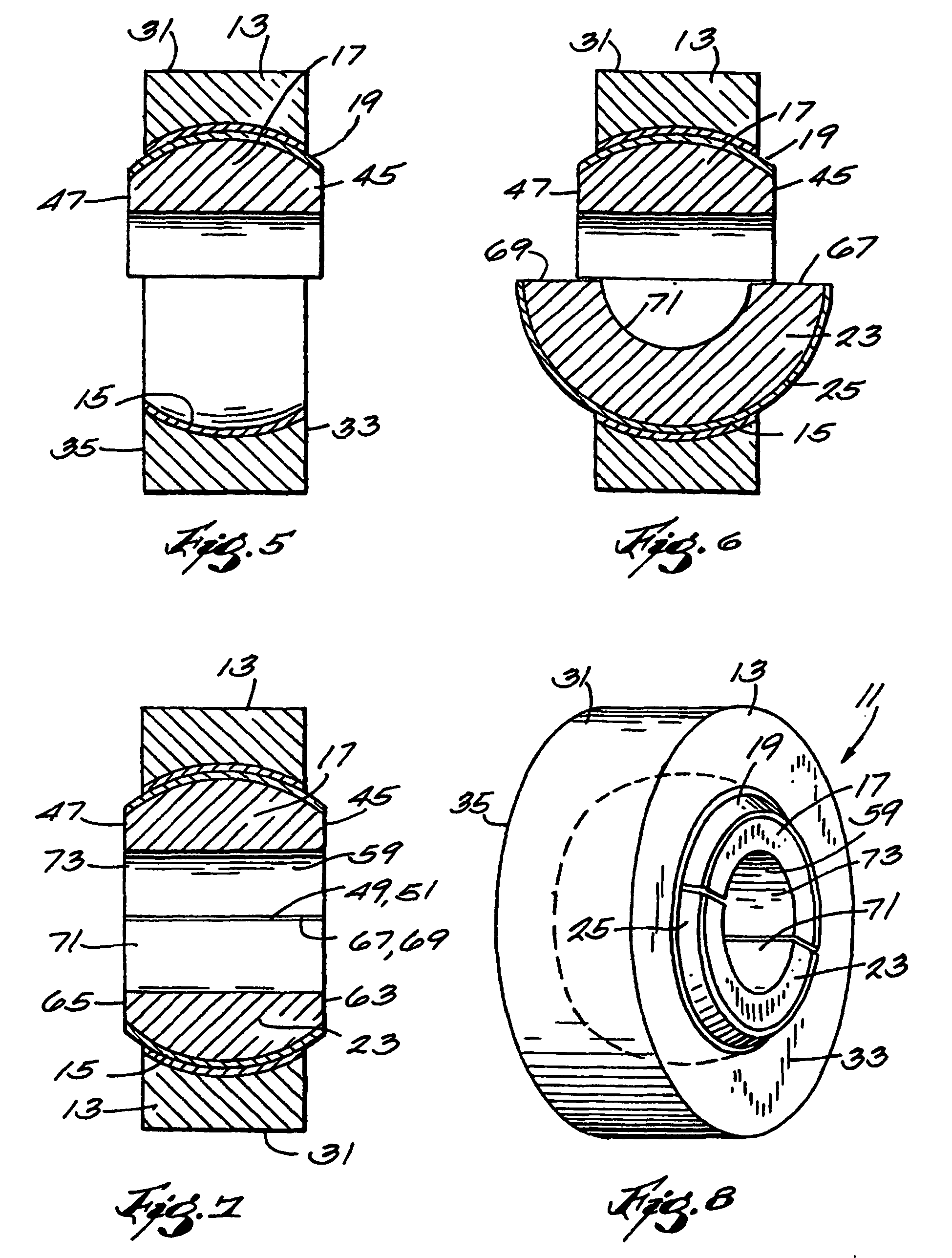
Figure 5 is a cross-sectional view illustrating completion of the insertion of one
of the inner bearing members into the outer bearing member.
Figure 6 is a cross-sectional view illustrating the initial of the insertion of the
second one of the inner bearing members into the outer bearing member.
Figure 7 is a cross-sectional view illustrating completion of the insertion of the
second one of the inner bearing members into the outer bearing member and is thus
also a cross-sectional view of the fully assembled bearing or bearing assembly.
Figure 8 is a perspective view of the fully assembled bearing or bearing assembly.
[0019] Before one embodiment of the invention is explained in detail, it is to be understood
that the invention is not limited in its application to the details of the construction
and the arrangements of components set forth in the following description or illustrated
in the drawings. The invention is capable of other embodiments and of being practiced
or being carried out in various ways within the scope of the claims. Also, it is-understood
that the phraseology and terminology used herein is for the purpose of description
and should not be regarded as limiting.
[0020] Illustrated in Figures 7 and 8 is one embodiment of a spherical bearing or bearing
assembly 11 which incorporates various of the features of the invention and which
includes an outer bearing or race member 13 including (see Figure 1) an inner concave
spherical bearing surface or surface segment 15, a first inner bearing or race member
or segment 17 extending circumferentially within the outer race member 13 and including
an outer partially spherical bearing surface or surface segment 19 fabricated of self-lubricating
material and engaging the inner bearing surface 15, and a second inner bearing or
race member or segment 23 extending circumferentially within the outer race member
13 and including an outer partially spherical bearing surface or surface segment 25
fabricated of self-lubricating material and engaging the inner bearing surface 15.
[0021] More particularly, and while other constructions can be employed, in the specifically
disclosed construction, the outer bearing or race member 13 includes an outer surface
31 which is generally cylindrical, but can be of any desired configuration, together
with spaced and parallel sides or side faces 33 and 35 which extend radially inwardly
from the outer surface 31, and the before mentioned inner concave spherical bearing
surface 15 which extends between the side faces 33 and 35 of the outer bearing or
race member 13.
[0022] The outer bearing or race member 13 can be fabricated from any suitable material,
such as steel or a resinous epoxy composite material, and in any suitable fashion.
In particular, the inner concave spherical bearing surface 15 can be the inner surface
of a metallic member, but, in the specifically disclosed construction, is shown as
the inner surface of a layer 39 of self-lubricating material which is bonded to a
resinous epoxy outer layer 41 and which, together with the outer layer 41, forms a
composite bearing structure.
[0023] While other constructions can be employed, in the specifically disclosed construction,
the first inner bearing or race member 17 extends circumferentially within the outer
race member 13 and includes spaced and parallel sides or side faces 45 and 47, together
with first and second circumferentially spaced and generally co-planar ends or end
faces 49 and 51 extending from the side faces 45 and 47 of the first inner bearing
or race member 17. In addition, the first inner bearing or race member 17 includes
the before mentioned outer spherical bearing surface or surface segment 19 which is
preferably fabricated of self-lubricating material, which extends between the side
faces 45 and 47 and the end faces 49 and 51 of the first inner bearing or race member
17, which is partially hemi-spherical throughout the area between the side faces 45
and 47 and the end faces 49 and 51, and which engages the inner bearing surface 15
of the outer bearing or race member 13.
[0024] Still further in addition, the first inner bearing or race member 17 includes an
inner concave semi-cylindrical surface 59 extending between the side faces 45 and
47 and the end faces 49 and 51 of the first inner bearing or race member 17.
[0025] While other constructions can be employed, in the specifically disclosed construction,
the second inner bearing or race member 23 extends circumferentially within the outer
bearing or race member 13 and includes spaced and parallel sides or side faces 63
and 65, together with first and second circumferentially spaced and generally co-planar
ends or end faces 67 and 69 extending from the side faces 63 and 65 of the second
inner bearing or race member 23. In addition, the second inner bearing or race member
23 includes the before mentioned outer spherical bearing surface or surface segments
25 which is preferably fabricated of self-lubricating material, which extends between
the side faces 63 and 65 and the end faces 67 and 69 of the second inner bearing or
race member 23, which is partially hemi-spherical throughout the area between the
side faces 63 and 65 and the end faces 67 and 69 of the second inner bearing or race
member 23, and which forms, with the outer convex partially hemi-spherical bearing
surface 19 of the first inner bearing or race member 13, an outer convex, partially
spherical bearing surface engaging the inner concave partially spherical bearing surface
of the outer race member 15.
[0026] The second inner bearing or race member 23 also includes an inner concave semi-cylindrical
surface 71 extending between the side faces 63 and 65 and the end faces 67 and 69
of the second inner bearing or race member 23, and forming, with the inner concave
semi-cylindrical surface 59 of the first inner bearing or race member 17, a cylindrical
bore 73. In other embodiments of the invention, the configuration of the inner bore
73 can be hexagonal, square, or some other geometry.
[0027] The first and second inner bearing or race members 17 and 23 are preferably fabricated
in accordance with the method described hereinafter. More specifically, the spherical
bearing assembly 11 is preferably formed in accordance with a preferred method which
includes the step of forming the outer bearing member 13 (as shown in Figure 1) with
the inner concave, partially spherical bearing surface 15.
[0028] The step of forming the outer bearing or race member 13 can also include forming
the outer bearing member 13 with the spaced and parallel side faces 33 and 35, and
such that the inner concave spherical bearing surface 15 extends between the side
faces 33 and 35 of the outer bearing member 13.
[0029] The method further includes the steps of forming a second member 81 (as shown in
Figure 2) with an outer convex, partially spherical bearing surface 83 of self-lubricating
material, and cutting the second member 81 along a diametric plane 84 to provide the
first and second inner bearing or race members or segments 17 and 23 respectively
including the first and second outer spherical bearing surfaces or segments 19 and
25. Any suitable means can be employed to cut the second member 81 along the diametrical
plane. However, it is preferred to cut the second member 81 with a thin diamond coated
wheel (not shown) which can be supported in any suitable manner.
[0030] The first and second inner bearing or race members 17 and 23 are thus of generally
identical construction.
[0031] The step of forming the second member 81 can also include forming the second member
81, either before or after forming the outer convex spherical bearing surface 83,
with spaced and parallel sides or side faces 85 and 87 such that the outer convex
spherical bearing surface 83 extends throughout the area between the side faces 85
and 87 of the second member 81 and such that the cutting takes place along the diametric
plane 84 which extends perpendicularly to the side faces 85 and 87.
[0032] More particularly, and while other specific methods can be employed, in the specifically
disclosed method, the step of forming the second member 81 preferably includes forming
the outer convex spherical bearing surface 83 of the second member 81 from self-lubricating
material. While other arrangements can be employed, it is preferred to form the second
member 81 as a composite of an outer layer 91 of self-lubricating material and an
inner body or layer 93 of resinous epoxy material as disclosed in U.S. application
Serial No. 09/09249 filed 5 June 1998 and entitled "Composite Spherical Bearing and
Method of Producing Same", (Attorney's Docket No. 65112/9545), which application is
incorporated herein by reference.
[0033] In particular, in one embodiment of the method of the invention, the second member
81 can be formed, as explained in greater detail in U.S. application Serial No. 09/09249
filed 5 June 1998 (Attorney's Docket No. 65112/9545), by the steps of fabricating
the inner supporting layer 93 of a fiberglass epoxy resin matrix which includes an
outer, outwardly convex, truncated spherical surface. Thereafter, a fabric of self-lubricating
material is placed on the outer, outwardly convex, truncated spherical surface of
the inner supporting layer 93 to partially form the outer layer 91 of self-lubricating
material. Thereafter, a layer of glass filaments and resin is placed on the outer
layer 91 of self-lubricating material so as to conform the outer layer 91 of self-lubricating
material to the outer, outwardly convex, truncated spherical surface of the inner
supporting layer 93. Thereafter, the last mentioned layer of glass filaments and resin
is cured to form an outer layer of fiberglass epoxy resin matrix and to bond the outer
layer 91 of self-lubricating material to the inner supporting layer 93 of fiberglass
epoxy resin matrix and to the last-mentioned outer layer of fiberglass epoxy resin
matrix. Thereafter, the last-mentioned outer layer of fiberglass epoxy resin matrix
is removed in any suitable manner to expose the outer layer 91 of self-lubricating
material without damaging the self-lubricating material. Thereafter, the outer layer
91 of self-lubricating material is formed with the outer, outwardly convex, spherical
surface 83.
[0034] As noted just above, the second member 81 is preferably formed from a resinous epoxy
material including the outer layer 91 of self-lubricating material which can be formed
to include the outer spherical surface 83 by any suitable technique, such as by machining
or grinding, or cutting, or by any combination thereof.
[0035] The step of forming the second member 81 can also include forming the second member
81 with the bore 73 which extends perpendicularly to the side faces 85 and 87 and
which can be either cylindrical or non-cylindrical, such as triangular, square, rectangular,
hexagonal or other non-cylindrical bore.
[0036] The step of cutting the second member 81 can also include cutting the first and second
inner bearing or race members or segments 17 and 23 to respectively include the first
and second spaced and parallel side faces or face segments 45 and 47, and 63 and 65,
and the first and second end faces 49 and 51 and 67 and 69 extending from the side
faces or face segments, and such that the first and second outer spherical bearing
surface segments 17 and 25 extend throughout the area between the side faces or face
segments 45 and 47 and 63 and 65 and the end faces 49 and 51, and 67 and 69.
[0037] Thereafter, the method includes (see Figure 4) the step of inserting the first inner
bearing or race
member or segment 17 within the outer bearing member 13 so as to fully engage the
first outer spherical bearing surface or surface segment 19 with the inner concave
spherical bearing surface 15 of the outer bearing or
race member 13.
[0038] The step of inserting the first inner bearing or race member or segment 17 includes
inserting the first bearing or race member or segment 17 within the outer bearing
member 13 in a direction perpendicular to the side faces 33 and 35 of the outer bearing
member 13 and with the spaced and parallel sides 45 and 47 of the first inner bearing
member or segment 17 in generally perpendicular relation to the spaced and parallel
sides 33 and 35 of the outer bearing or race member 13 and so as to partially engage
the first outer spherical bearing surface or segment 19 with the inner concave spherical
bearing surface 15.
[0039] Thereafter, the first inner bearing member or segment 17 is rotated within the outer
bearing member 13 so as to locate the spaced and parallel sides 45 and 47 of the first
inner bearing member or segment 17 in parallel relation to the spaced and parallel
sides 33
and 35 of the outer bearing member 13 and so as to
fully engage the first outer spherical bearing surface with the inner concave spherical
bearing surface 15 of the outer bearing or race member 13.
[0040] Thereafter, the method includes (see Figure 6) the step of inserting the second inner
bearing or race
member or segment 23 within the outer bearing member 13 so as to fully engage the
second outer spherical
bearing surface or surface segment 25 with the inner concave spherical bearing surface
15 of the outer
bearing or race member 13.
[0041] The step of inserting the second inner bearing member or segment 23 includes inserting
the second
inner bearing member or segment 23 within the outer bearing or race member 13 in a
direction perpendicular
to the side faces 33 and 35 of the outer bearing or
race member 13 and with the spaced and parallel sides
63 and 65 of the second inner bearing member or segment 23 in generally perpendicular
relation to the spaced
and parallel sides 33 and 35 of the outer bearing or race member 13 and with the end
faces 67 and 69 of the second inner bearing member or segment 23 in generally coplanar
and spaced relation to the end faces 49 and 51 of the first inner bearing member or
segment 17 and so
as to partially engage second outer spherical bearing surface or segment 23 with the
inner concave spherical bearing surface 15 of the outer bearing or race member 13.
[0042] Thereafter, the second inner bearing member or segment 23 is rotated within the outer
bearing or race member 13 so as to locate the end faces 67 and 69 of the second inner
bearing member or segment 23 in abutting relation to the end faces 49 and 51 of the
first inner bearing member or segment 17 and so as to fully engage the second bearing
surface or segment 25 with the inner bearing surface 15 of the outer bearing or race
member 13.
[0043] The disclosed construction advantageously provides a self-lubricating inner spherical
bearing member or race that can be easily installed and removed from an associated
outer race or bearing member without taking the outer race or bearing member from
the supporting housing or removing the supporting housing from the associated structure.
Thus, the disclosed construction advantageously allows for installation and removal
of the spherical segments of the inner race while the housing for the overall bearing
assembly remains intact.
[0044] In the disclosed construction, positioning or orientation of the inner bearing segments
of the disclosed construction is no longer dependent on the orientation of the load,
as is the case when bearing members with entry slots are used or when bearings having
spherical balls with flats are used.
[0045] In addition, the disclosed construction provides a bearing with improved load capacity
because the slots in the prior outer races have been eliminated and because the flats
in the prior spherical balls have been eliminated.
[0046] Another of the advantages of the disclosed construction is that (due to the elimination
of the prior slots and flats) positioning of the spherical segments is no longer dependent
on the orientation of the load.
[0047] Various of the features of the invention are set forth in the following claims.
1. A method of making a spherical bearing (11) comprising the steps of:
- forming an outer bearing member (13) with an inner concave spherical bearing surface
(15),
- providing first and second inner bearing segments (17, 23), respectively including
first and second outer spherical bearing surface segments (19, 25), at least one of
the inner and outer spherical bearing surfaces being of self-lubricating material,
- inserting the first inner bearing segment (17) within the outer bearing member (13)
so as to fully engage the first outer spherical bearing surface segment (19) with
the inner concave spherical bearing surface (15), and
- inserting the second inner bearing segment (23) within the outer bearing member
(13) so as to fully engage the second outer spherical bearing surface segment (25)
with the inner concave spherical bearing surface (15),
characterized in that,
the first and second inner bearing segments (17, 23) are provided by forming a second
member (81) with an outer convex spherical bearing surface (83) and by cutting said
second member (81) along a diametric plane (84).
2. A method in accordance with Claim 1 wherein the step of forming the second member
(81) includes forming the outer convex spherical bearing surface (83) of the second
member (81) from self-lubricating material.
3. A method in accordance with Claim 1 or Claim 2 wherein the step of forming the outer
bearing member (13) includes forming the outer bearing member (13) with spaced and
parallel side faces (33, 35), and wherein the inner concave spherical bearing surface
(15) extends between the side faces (33, 35) of the outer bearing member.
4. A method in accordance with any one of the preceding Claims wherein the step of forming
the second member (81) includes forming the second member (81) with spaced and parallel
side faces (85, 87), and wherein the outer convex spherical bearing surface (83) extends
between the side faces (85, 87) of the second member (81).
5. A method in accordance with Claim 4 wherein the step of forming the second member
(81) also includes forming the second member with a bore (73) extending perpendicularly
to the side faces (85, 87).
6. A method in accordance with any one of the preceding Claims, wherein the outer bearing
member(13) is circumferentially continuous.
7. A method in accordance with any one of the preceding Claims, wherein the inner bearing
segments (17, 23) are formed by the step of cutting an initially circumferentially
continuous second member (81).
8. A method in accordance with Claim 7 wherein the step of cutting the second member
(81) includes cutting the first and second bearing segments (17, 23) to respectively
include first and second spaced and parallel side faces segments (45, 47; 63, 65),
and first and second end faces (49, 51; 67, 69) extending from the side face segments,
and wherein the first and second outer spherical bearing surface segments (19, 25)
extend between the side face segments (45, 47; 63, 65) and the end faces (49, 51;
67, 69).
9. A method in accordance with any one of the preceding Claims wherein the step of forming
the outer bearing member (13) includes forming the outer bearing member (13) with
spaced and parallel side faces (33, 35), wherein the step of cutting the second member
includes cutting the first and second inner bearing segments (17, 23) to respectively
include first and second spaced and parallel side faces segments (45, 47; 63, 65),
and first and second end faces (49, 51; 67, 69) joining the side face segments, wherein
said step of inserting the first inner bearing segment (17) includes inserting the
first inner bearing segment within the outer bearing member (13) in a direction perpendicular
to the side faces (33, 35) of the outer bearing member (13) and with the spaced and
parallel sides (45, 47) of the first inner bearing segment (17) in generally perpendicular
relation to the spaced and parallel sides (33, 35) of the outer bearing member (13)
so as to partially engage the first outer spherical bearing surface segment (19) with
the inner concave spherical bearing surface (15), and thereafter rotating the first
inner bearing segment (17) within the outer bearing member (13) so as to locate the
spaced and parallel sides (45, 47) of the first inner bearing segment (17) in parallel
relation to the spaced and parallel sides (33, 35) of the outer bearing member (13)
and so as to fully engage the first outer spherical bearing surface segment (19) with
the inner concave spherical bearing surface (15).
10. A method in accordance with any one of the preceding Claims wherein the step of forming
the outer bearing member (13) includes forming the outer bearing member with spaced
and parallel side faces (33, 35), wherein the step of cutting the second member includes
cutting the first and second bearing segments (17, 23) to respectively include first
and second spaced and parallel side faces segments (45, 47; 63, 65), and first and
second end faces (49, 51; 67, 69) extending from the side face segments, and wherein
said step of inserting the second inner bearing segment (23) includes inserting the
second inner bearing segment within the outer bearing member in a direction perpendicular
to the side faces of the outer bearing member (13) and with the spaced and parallel
sides (63, 65) of the second inner bearing segment (23) in generally perpendicular
relation to the spaced and parallel sides (33, 35) of the outer bearing member (13)
and with the end faces (67, 69) of the second inner bearing segment (23) in generally
coplanar and spaced relation to the end faces (49, 51) of the first inner bearing
segment (17) and so as to partially engage second outer spherical bearing surface
segment (25) with the inner concave spherical bearing surface (15), and thereafter
rotating the second inner bearing segment (23) within the outer bearing member (13)
so as to locate the end faces (67, 69) of the second inner bearing segment (23) in
abutting relation to the end faces (49, 51) of the first inner bearing segment (17)
and so as to fully engage the second inner bearing surface segment (25) with the inner
concave spherical bearing surface (15) of the outer bearing member (13).
11. A method according to claim 1, wherein the outer bearing member (13) is formed with
spaced and parallel side faces (33, 35) and the inner concave spherical bearing surface
(15) extends between the side faces (33, 35) of the outer bearing member (13), wherein
the second member (81) is formed with spaced and parallel side faces (85, 87) and
the outer convex spherical bearing surface (83) extends between the side faces (85,
87) of the second member (81), wherein the diametric plane (84) along with the second
member (81) is cut extends perpendicularly to the side faces (85, 87) thereof wherein
the first and second bearing segments including first and second spaced and parallel
side faces segments (45, 47; 63, 65), first and second end faces (49, 51; 67, 69)
extending between the side face segments, and wherein the first and second outer truncated
spherical bearing surface segments (19, 25) extend between the side face segments
and the end faces, wherein the first bearing segment (17) is inserted within the outer
bearing member (13) in a direction perpendicular to the side faces (33, 35) of the
outer bearing member (13) and with the spaced and parallel sides (45, 47) of the first
bearing segment (17) in generally perpendicular relation to the spaced and parallel
sides (33, 35) of the outer bearing member (13) and so as to partially engage the
first outer truncated spherical bearing surface segment (19) with the inner concave
spherical bearing surface (15) and wherein the first bearing segment (17) is rotated
within the outer bearing member (13) so as to locate the spaced and parallel sides
(45, 47) of the first bearing segment (17) in parallel relation to the spaced and
parallel sides (33, 35) of the outer bearing member (13) and so as to fully engage
the first outer spherical bearing surface segment (19) with the inner concave spherical
bearing surface (15), wherein the second bearing segment (23) is inserted within the
outer bearing member (13) in a direction perpendicular to the side faces (33, 35)
of the outer bearing member (13) and with the spaced and parallel sides (63, 65) of
the second bearing segment (23) in generally perpendicular relation to the spaced
and parallel sides (33, 35) of the outer bearing member (13) and with the end faces
(67, 69) of the second bearing segment (23) in generally coplanar and spaced relation
to the end faces (49, 51) of the first bearing segment (17) and so as to partially
engage second outer spherical bearing surface segments (25) with the inner concave
spherical bearing surface (15), and wherein the second bearing segment (23) is rotated
within the outer bearing member (13) so as to locate the end faces (67, 69) of the
second bearing segment (23) in abutting relation to the end faces (49, 51) of the
first bearing segment (17) and so as to fully engage the second bearing surface segment
(25) with the inner bearing surface (15) of the outer bearing member (13).
12. A method in accordance with Claim 11 wherein the step of forming the second member
(81) also includes forming the second member (81) with a bore (73) extending perpendicularly
to the side faces (85, 87)
13. A method in accordance with any one of the preceding claims, wherein the step of forming
the second member (81) also includes forming the second member (81) with a cylindrical
bore (73) extending perpendicularly to the side faces (85, 87).
14. A method in accordance with any one of claims 1-12, wherein the step of forming the
second member (81) also includes forming the second member (81) with a bore extending
perpendicularly to the side faces wherein the bore is of hexagonal, square or some
other geometry.
15. A method in accordance with any one of Claim 11-14 wherein the step of forming the
second member (81) includes the steps of fabricating an inner supporting layer (93)
of a fibreglass epoxy resin matrix which includes an outer, outwardly convex, truncated
spherical surface, placing a fabric of self-lubricating material on the outer, outwardly
convex, truncated spherical surface of the inner supporting layer (93) to partially
form an outer layer (91) of self-lubricating material, placing another layer of fibreglass
filaments and epoxy resin on the outer layer (91) of self-lubricating material so
as to conform the outer layer of self-lubricating material to the outer, outwardly
convex, truncated spherical surface of the inner supporting layer (93), curing the
last mentioned layer of fibreglass filaments and epoxy resin to form an outer layer
(91) of fibreglass epoxy resin matrix and to bond the outer layer of self-lubricating
material to the inner supporting layer (93) of fibreglass epoxy resin matrix and to
the last-mentioned outer layer of fibreglass epoxy resin matrix, removing the last-mentioned
outer layer of fibreglass epoxy resin matrix to expose the outer layer of self-lubricating
material (91), and forming the outer layer of self-lubricating material (91) with
the outer convex spherical bearing surface.
16. A method in accordance with any one of the preceding Claims wherein the first and
second inner bearing segments (17, 23) each extend through 180 DEG about the major
axis of rotation of the bearing.
17. A spherical bearing (11) comprising an outer race member (13) including an inner concave
spherical bearing surface (15), two inner bearing members (17, 23) extending in a
circumferential direction within said outer race member (13) and each including an
outer spherical bearing surface (19, 25) engaging said inner bearing surface (15),
and at least one of the inner and outer bearing surfaces (15; 19, 25) being fabricated
of self-lubricating material characterized in that, the two inner bearing members (17, 23) lie at respective sides of a diametric plane
(84) which contains the major axis of said inner concave spherical bearing surface
(15).
18. A spherical bearing according to Claim 17 wherein the outer race member (13) is circumferentially
continuous.
19. A spherical bearing in accordance with any one of Claims 17 or 18 and comprising two
inner bearing members (17, 23) which each extend through 180 DEG about the major axis
of said inner concave spherical bearing surface (15).
20. A spherical bearing in accordance with any one of Claims 17 to 19 wherein said outer
race member (13) also includes spaced and parallel side faces (33, 35), and wherein
said inner concave spherical bearing surface (15) extends between said side faces
(33, 35) of the outer bearing member (13).
21. A spherical bearing in accordance with any one of Claims 17-20 wherein each of said
first and second inner bearing members (17, 23) also include spaced and parallel side
faces (45, 47; 63, 65), and first and second circumferentially spaced and generally
coplanar end faces (49, 51; 67, 69) extending from said side faces of said member,
wherein said outer convex spherical bearing surface (19) of said member (17) extends
in unbroken condition between said end faces and said side faces of said member, and
wherein said outer convex spherical bearing surface of said second member (23) extends
in unbroken condition between said end faces and said side faces of said second member.
22. A spherical bearing in accordance with Claim 21 wherein each of said first and second
inner bearing members (17, 23) also include an inner concave semi-cylindrical surface
(59, 71) whereby the first and second inner bearing members (17, 23) define a cylindrical
bore (73).
1. Verfahren zur Herstellung eines sphärischen Lagers (11), umfassend die Schritte:
- Ausbilden eines äußeren Lagerelements (13) mit einer inneren konkaven sphärischen
Lageroberfläche (15),
- Bereitstellen von ersten und zweiten inneren Lagersegmenten (17, 23), welche jeweils
erste und zweite äußere sphärische Lageroberflächensegmente (19, 25) enthalten, wobei
zumindest eine von den inneren und äußeren sphärischen Lageroberflächen aus selbstschmierendem
Material ist,
- Einsetzen des ersten inneren Lagersegments (17) innerhalb des äußeren Lagerelements
(13), um so das erste äußere sphärische Lageroberflächensegment (19) mit der inneren
konkaven sphärischen Lageroberfläche (15) vollständig in Eingriff zu bringen, und
- Einsetzen des zweiten inneren Lagersegments (23) innerhalb des äußeren Lagerelements
(13), um so das zweite äußere sphärische Lageroberflächensegment (25) mit der inneren
konkaven sphärischen Lageroberfläche (15) vollständig in Eingriff zu bringen,
dadurch gekennzeichnet, dass
die ersten und zweiten inneren Lagersegmente (17, 23) durch Ausbilden eines zweiten
Elements (81) mit einer äußeren konvexen sphärischen Lageroberfläche (83) und durch
Schneiden des zweiten Elements (81) entlang einer diametrischen Ebene (84) bereitgestellt
werden.
2. Verfahren gemäß Anspruch 1, wobei der Schritt des Ausbildens des zweiten Elements
(81) ein Ausbilden der äußeren konvexen sphärischen Lageroberfläche (83) des zweiten
Elements (81) aus selbstschmierendem Material enthält.
3. Verfahren gemäß Anspruch 1 oder 2, wobei der Schritt des Ausbildens des äußeren Lagerelements
(13) ein Ausbilden des äußeren Lagerelements (13) mit beabstandeten und parallelen
Seitenflächen (33, 35) enthält, und wobei die innere konkave sphärische Lageroberfläche
(15) sich zwischen den Seitenflächen (33, 35) des äußeren Lagerelements erstreckt.
4. Verfahren gemäß einem der vorhergehenden Ansprüche, wobei der Schritt des Ausbildens
des zweiten Elements (81) ein Ausbilden des zweiten Elements (81) mit beabstandeten
und parallelen Seitenflächen (85, 87) enthält, und wobei die äußere konvexe sphärische
Lageroberfläche (83) sich zwischen den Seitenflächen (85, 87) des zweiten Elements
(81) erstreckt.
5. Verfahren gemäß Anspruch 4, wobei der Schritt des Ausbildens des zweiten Elements
(81) ebenso das Ausbilden des zweiten Elements mit einer Bohrung (73) enthält, welche
sich senkrecht zu den Seitenflächen (85, 87) erstreckt.
6. Verfahren gemäß einem der vorhergehenden Ansprüche, wobei das äußere Lagerelement
(13) umfänglich kontinuierlich ist.
7. Verfahren gemäß einem der vorhergehenden Ansprüche, wobei die inneren Lagersegmente
(17, 23) durch den Schritt des Schneidens eines anfänglich umfänglich kontinuierlichen
zweiten Elements (81) ausgebildet werden.
8. Verfahren gemäß Anspruch 7, wobei der Schritt des Schneidens des zweiten Elements
(81) das Schneiden der ersten und zweiten Lagersegmente (17, 23) dahingehend enthält,
dass jeweils erste und zweite beabstandete und parallele Seitenflächensegmente (45,
47; 63, 65) und erste und zweite Endflächen (49, 51; 67, 69) enthalten sind, welche
sich von den Seitenflächensegmenten erstrecken, und wobei die ersten und zweiten äußeren
sphärischen Lageroberflächensegmente (19, 25) sich zwischen den Seitenflächensegmenten
(45, 47; 63, 65) und den Endflächen (49, 51; 67, 69) erstrecken.
9. Verfahren gemäß einem der vorhergehenden Ansprüche, wobei der Schritt des Ausbildens
des äußeren Lagerelements (13) das Ausbilden des äußeren Lagerelements (13) mit beabstandeten
und parallelen Seitenflächen (33, 35) enthält, wobei der Schritt des Schneidens des
zweiten Elements das Schneiden der ersten und zweiten inneren Lagersegmente (17, 23)
dahingehend enthält, jeweils erste und zweite beabstandete und parallele Seitenflächensegmente
(45, 47; 63, 65) und erste und zweite Endflächen (49, 51; 67, 69) zu enthalten, die
mit den Seitenflächensegmenten verbunden sind, wobei der Schritt des Einsetzens des
ersten inneren Lagersegments (17) ein Einsetzen des ersten inneren Lagersegments innerhalb
des äußeren Lagerelements (13) in einer Richtung senkrecht zu den Seitenflächen (33,
35) des äußeren Lagerelements (13) enthält, und wobei die beabstandeten und parallelen
Seitenflächen (45, 47) des ersten inneren Lagersegments (17) in allgemein senkrechter
Relation zu den beabstandeten und parallelen Seiten (33, 35) des äußeren Lagerelements
(13) sind, um so teilweise in das erste äußere sphärische Lageroberflächensegment
(19) mit der inneren konkaven sphärischen Lageroberfläche (15) einzugreifen, und anschließend
das erste innere Lagersegment (17) innerhalb des äußeren Lagerelements (13) zu rotieren,
um so die beabstandeten und parallelen Seiten (45, 47) des ersten inneren Lagersegments
(17) in paralleler Relation zu den beabstandeten und parallelen Seiten (33, 35) des
äußeren Lagerelements (13) anzuordnen und um so das erste äußere sphärische Lageroberflächensegment
(19) mit der inneren konkaven sphärischen Lageroberfläche (15) vollständig in Eingriff
zu bringen.
10. Verfahren gemäß einem der vorhergehenden Ansprüche, wobei der Schritt des Ausbildens
des äußeren Lagerelements (13) das Ausbilden des äußeren Lagerelements mit beabstandeten
und parallelen Seitenflächen (33, 35) enthält, wobei der Schritt des Schneidens des
zweiten Elements das Schneiden der ersten und zweiten Lagersegmente (17, 23) enthält,
um jeweils erste und zweite beabstandete und parallele Seitenflächensegmente (45,
47; 63, 65) zu enthalten, und erste und zweite Endflächen (49, 51; 67, 69), welche
sich von den Seitenflächensegmenten erstrecken, zu erhalten, und wobei der Schritt
des Einsetzens des zweiten inneren Lagersegments (23) das Einsetzen des zweiten inneren
Lagersegments innerhalb des äußeren Lagerelements in einer Richtung senkrecht zu den
Seitenflächen des äußeren Lagerelements (13) enthält, und wobei die beabstandeten
und parallelen Seiten (63, 65) des zweiten inneren Lagersegments (23) in allgemein
senkrechter Relation zu den beabstandeten und parallelen Seitenflächen (33, 35) des
äußeren Lagerelements (13), und die Endflächen (67, 69) des zweiten inneren Lagersegments
(23) in allgemein koplanarer und beabstandeter Relation zu den Endflächen (49, 51)
des ersten inneren Lagersegments (17) sind, und um so teilweise das zweite äußere
sphärische Lageroberflächensegment (25) mit der inneren konkaven sphärischen Lageroberfläche
(15) in Eingriff zu bringen, und anschließend das zweite innere Lagersegment (23)
innerhalb des äußeren Lagerelements (13) zu rotieren, um so die Endfläche (67, 69)
des zweiten inneren Lagersegments (23) in anliegender Relation zu den Endflächen (49,
51) des ersten inneren Lagersegments (17) anzuordnen, und um so das zweite innere
Lageroberflächensegment (25) mit der inneren konkaven sphärischen Lageroberfläche
(15) des äußeren Lagerelements (13) in vollständigen Eingriff zu bringen.
11. Verfahren gemäß Anspruch 1, wobei das äußere Lagerelement (13) mit beabstandeten und
parallelen Seitenflächen (33, 35) ausgebildet ist und sich die innere konkave sphärische
Lageroberfläche (15) zwischen den Seitenflächen (33, 35) des äußeren Lagerelements
(13) erstreckt, wobei das zweite Element (81) mit beabstandeten und parallelen Seitenflächen
(85, 87) ausgebildet ist, und sich die äußere konvexe sphärische Lageroberfläche (83)
zwischen den Seitenflächen (85, 87) des zweiten Elements (81) erstreckt, wobei die
diametrische Ebene (84),entlang welcher das zweite Element (81) geschnitten ist, sich
senkrecht zu den Seitenflächen (85, 87) desselben erstreckt, wobei die ersten und
zweiten Lagersegmente erste und zweite beabstandete und parallele Seitenflächensegmente
(45, 47; 63, 65), erste und zweite Endflächen (49, 51; 67, 69) enthalten, welche sich
zwischen den Seitenflächensegmenten erstrecken, und wobei die ersten und zweiten äußeren
abgeschnittenen sphärischen Lageroberflächensegmente (19, 25) sich zwischen den Seitenflächensegmenten
und den Endflächen erstrecken, wobei das erste Lagersegment (17) innerhalb des äußeren
Lagerelements (13) in einer Richtung senkrecht zu den Seitenflächen (33, 35) des äußeren
Lagerelements (13) eingesetzt ist, und wobei die beabstandeten und parallelen Seiten
(45, 47) des ersten Lagersegments (17) in allgemein senkrechter Relation zu den beabstandeten
und parallelen Seiten (33, 35) des äußeren Lagerelements (13) sind, und um so teilweise
das erste äußere abgeschnittene sphärische Lageroberflächensegment (19) mit der inneren
konkaven sphärischen Lageroberfläche (15) in Eingriff zu bringen, und wobei das erste
Lagersegment (17) innerhalb des äußeren Lagerelements (13) rotiert wird, um so die
beabstandeten und parallelen Seiten (45, 47) des ersten Lagersegments (17) in parallele
Relation zu den beabstandeten und parallelen Seiten (33, 35) des äußeren Lagerelements
(13) zu bringen, und um so das erste äußere sphärische Lageroberflächensegment (19)
mit der inneren konkaven sphärischen Lageroberfläche (15) in vollständigen Eingriff
zu bringen, wobei das zweite Lagersegment (23) innerhalb des äußeren Lagerelements
(13) in einer Richtung senkrecht zu den Seitenflächen (33, 35) des äußeren Lagerelements
(13) eingesetzt ist, und wobei die beabstandeten und parallelen Seiten (62, 65) des
zweiten Lagersegments (23) in allgemein senkrechter Relation zu den beabstandeten
und parallelen Seiten (33, 35) des äußeren Lagerelements (13) sind, und wobei die
Endflächen (67, 69) des zweiten Lagersegments (23) in allgemein koplanarer und beabstandeter
Relation zu den Endflächen (49, 51) des ersten Lagersegments (17) sind, und um so
zweite äußere sphärische Lageroberflächensegmente (25) mit der inneren konkaven sphärischen
Lageroberfläche (15) in teilweisen Eingriff zu bringen, und wobei das zweite Lagersegment
(23) innerhalb des äußeren Lagerelements (13) rotiert wird, um so die Endflächen (67,
69) des zweiten Lagersegments (23) in anliegender Relation zu den Endflächen (49,
51) des ersten Lagersegments (17) anzuordnen, und um so das zweite Lageroberflächensegment
(25) in vollständigen Eingriff mit der inneren Lageroberfläche (15) des äußeren Lagerelements
(13) zu bringen.
12. Verfahren gemäß Anspruch 11, wobei der Schritt des Ausbildens des zweiten Elements
(81) auch ein Ausbilden des zweiten Elements (81) mit einer Bohrung (73) enthält,
welche sich senkrecht zu den Seitenflächen (85, 87) erstreckt.
13. Verfahren gemäß einem der vorhergehenden Ansprüche, wobei der Schritt des Ausbildens
des zweiten Elements (81) auch das Ausbilden des zweiten Elements (81) mit einer zylindrischen
Bohrung (73) enthält, welche sich senkrecht zu den Seitenflächen (85, 87) erstreckt.
14. Verfahren gemäß einem der Ansprüche 1 bis 12, wobei der Schritt des Ausbildens des
zweiten Elements (81) auch das Ausbilden des zweiten Elements (81) mit einer Bohrung
enthält, welche sich senkrecht zu den Seitenflächen erstreckt, wobei die Bohrung von
hexagonaler, quadratischer oder einer anderen Geometrie ist.
15. Verfahren gemäß einem der Ansprüche 11 bis 14, wobei der Schritt des Ausbildens des
zweiten Elements (81) die Schritte enthält: Herstellen einer inneren Tragschicht (93)
aus einer Fiberglas/Epoxyharz-Matrix, welche eine äußere, nach außen konvexe, abgeschnitten
sphärische Oberfläche enthält, Anordnen eines Textils aus selbstschmierendem Material
auf die äußere, nach außen konvexe, abgeschnitten sphärische Oberfläche der inneren
Tragschicht (93), um teilweise eine äußere Schicht (91) von selbstschmierendem Material
auszubilden, Anordnen einer weiteren Schicht aus Fiberglasfilamenten und Epoxyharz
auf der äußeren Schicht (91) aus selbstschmierendem Material, um so die äußere Schicht
aus selbstschmierendem Material an die äußere, nach außen konvexe, abgeschnitten sphärische
Oberfläche der inneren Tragschicht (93) anzupassen, Aushärten der letztgenannten Schicht
aus Fiberglasfilamenten und Epoxyharz, um eine äußere Schicht (91) einer Fiberglas/Epoxyharz-Matrix
auszubilden, und um die äußere Schicht aus selbstschmierendem Material mit der inneren
Tragschicht (93) einer Fiberglas/Epoxyharz-Matrix und an die letztgenannte äußere
Schicht einer Fiberglas/Epoxyharz-Matrix zu binden, Entfemen der letztgenannten äußeren
Schicht einer Fiberglas/Epoxyharz-Matrix, um die äußere Schicht des selbstschmierenden
Materials (91) zu exponieren, und Ausbilden der äußeren Schicht aus selbstschmierendem
Material (91) mit der äußeren konvexen, sphärischen Lageroberfläche.
16. Verfahren gemäß einem der vorhergehenden Ansprüche, wobei die ersten und zweiten inneren
Lagersegmente (17, 23) sich beide um 180° um die Hauptachse der Drehung des Lagers
erstrecken.
17. Sphärisches Lager (11), umfassend ein äußeres Laufelement (13), welches eine innere
konkave sphärische Lageroberfläche (15), zwei innere Lagerelemente (17, 23), die sich
in einer Umfangsrichtung mit dem äußeren Laufelement (13) erstrecken und alle eine
äußere sphärische Lageroberfläche (19, 25) enthalten, die in die innere Lageroberfläche
(15) eingreift, und zumindest eine der inneren und äußeren Lageroberflächen (15; 19,
25) enthält, welche aus selbstschmierendem Material hergestellt sind,
dadurch gekennzeichnet, dass die zwei inneren Lagerelemente (17, 23) an jeweiligen Seiten einer diametrischen
Ebene (84) liegen, welche die Hauptachse der inneren konkaven, sphärischen Lageroberfläche
(15) enthält.
18. Sphärisches Lager gemäß Anspruch 17, wobei das äußere Laufelement (13) umfänglich
kontinuierlich ist.
19. Sphärisches Lager gemäß einem der Ansprüche 17 oder 18, umfassend zwei innere Lagerelemente
(17, 23), welche sich um 180° um die Hauptachse der inneren konkaven, sphärischen
Lageroberfläche (15) erstrecken.
20. Sphärisches Lager gemäß einem der Ansprüche 17 bis 19, wobei das äußere Laufelement
(13) auch beabstandete und parallele Seitenflächen (17, 23) enthält, und wobei die
innere konkave, sphärische Lageroberfläche (15) sich zwischen den Seitenflächen (17,
23) des äußeren Lagerelements (13) erstreckt.
21. Sphärisches Lager gemäß einem der Ansprüche 17 bis 20, wobei jedes der ersten und
zweiten inneren Lagerelemente (17, 23) auch beabstandete und parallele Seitenflächen
(45, 47; 63, 65), und erste und zweite umfänglich beabstandete und allgemein koplanare
Endflächen (49, 51; 67, 69) enthalten, welche sich von den Seitenflächen des Elements
erstrecken, wobei die äußere konvexe sphärische Lageroberfläche (19) des Elements
(17) sich in ungebrochenem Zustand zwischen den Endflächen und den Seitenflächen des
Elements erstrecken, und wobei die äußere konvexe, sphärische Lageroberfläche des
zweiten Elements (23) sich in ungebrochenem Zustand zwischen Endflächen und den Seitenflächen
des zweiten Elements erstreckt.
22. Sphärisches Lager gemäß Anspruch 21, wobei jedes der ersten und zweiten inneren Lagerelemente
(17, 23) auch eine innere konkave, halbzylindrische Oberfläche (59, 71) enthält, wodurch
die ersten und zweiten inneren Lagerelemente (17, 23) eine zylindrische Bohrung (73)
begrenzen.
1. Procédé de fabrication d'un palier sphérique (11), comprenant les étapes qui consistent
à:
- former un élément de palier extérieur (13) comportant une surface d'appui sphérique
intérieure concave (15),
- prévoir des premier et second segments de palier intérieurs (17, 23) comprenant
respectivement des premier et second segments de surface d'appui sphérique extérieure
(19, 25), l'une au moins des surfaces d'appui sphériques intérieure et extérieure
étant formée d'une matière autolubrifiante,
- insérer le premier segment de palier intérieur (17) dans l'élément de palier extérieur
(13) de façon que le premier segment de surface d'appui sphérique extérieure (19)
soit totalement en contact avec la surface d'appui sphérique intérieure concave (15),
et
- insérer le second segment de palier intérieur (23) dans l'élément de palier extérieur
(13) de façon que le second segment de surface d'appui sphérique extérieure (25) soit
totalement en contact avec la surface d'appui sphérique intérieure concave (15),
caractérisé en ce que
les premier et second segments de palier intérieurs (17, 23) sont définis par la formation
d'un second élément (81) comportant une surface d'appui sphérique extérieure convexe
(83) et par la coupe dudit second élément (81) le long d'un plan diamétral (84).
2. Procédé selon la revendication 1, dans lequel l'étape de formation du second élément
(81) comprend la formation de la surface d'appui sphérique extérieure convexe (83)
de celui-ci à partir d'une matière autolubrifiante.
3. Procédé selon la revendication 1 ou la revendication 2, dans lequel l'étape de formation
de l'élément de palier extérieur (13) comprend la formation, sur celui-ci, de faces
latérales espacées et parallèles (33, 35), et dans lequel la surface d'appui sphérique
intérieure concave (15) s'étend entre les faces latérales (33, 35) de l'élément de
palier extérieur (13).
4. Procédé selon l'une quelconque des revendications précédentes, dans lequel l'étape
de formation du second élément (81) comprend la formation, sur celui-ci, de faces
latérales espacées et parallèles (85, 87), et dans lequel la surface d'appui sphérique
extérieure convexe (83) s'étend entre les faces latérales (85, 87) du second élément
(81).
5. Procédé selon la revendication 4, dans lequel l'étape de formation du second élément
(81) comprend également la formation, dans celui-ci, d'un alésage (73) s'étendant
perpendiculairement aux faces latérales (85, 87).
6. Procédé selon l'une quelconque des revendications précédentes, dans lequel l'élément
de palier extérieur (13) est continu circonférentiellement.
7. Procédé selon l'une quelconque des revendications précédentes, dans lequel les segments
de palier intérieurs (17, 23) sont formés par l'étape de coupe d'un second élément
(81) initialement continu circonférentiellement.
8. Procédé selon la revendication 7, dans lequel l'étape de coupe du second élément (81)
comprend la coupe des premier et second segments de palier (17, 23) pour qu'ils comprennent
respectivement des premier et second segments de face latérale espacés et parallèles
(45, 47; 63, 65) et des première et seconde faces d'extrémité (49, 51; 67, 69) s'étendant
à partir des segments de face latérale, et dans lequel les premier et second segments
de surface d'appui sphérique extérieure (19, 25) s'étendent entre les segments de
face latérale (45, 47; 63, 65) et les faces d'extrémité (49, 51; 67, 69).
9. Procédé selon l'une quelconque des revendications précédentes, dans lequel l'étape
de formation de l'élément de palier extérieur (13) comprend la formation, sur celui-ci,
de faces latérales espacées et parallèles (33, 35), dans lequel l'étape de coupe du
second élément (81) comprend la coupe des premier et second segments de palier intérieurs
(17, 23) pour qu'ils comprennent respectivement des premier et second segments de
face latérale espacés et parallèles (45, 47; 63, 65) et des première et seconde faces
d'extrémité (49, 51; 67, 69) reliant les segments de face latérale, et dans lequel
ladite étape d'insertion du premier segment de palier intérieur (17) comprend l'insertion
de celui-ci dans l'élément de palier extérieur (13) dans une direction perpendiculaire
aux faces latérales (33, 35) de ce dernier et de façon que les côtés espacés et parallèles
(45, 47) du premier segment de palier intérieur (17) soient dans une relation de manière
générale perpendiculaire aux côtés espacés et parallèles (33, 35) de l'élément de
palier extérieur (13), afin que le premier segment de surface d'appui sphérique extérieure
(19) soit partiellement en contact avec la surface d'appui sphérique intérieure concave
(15), puis la rotation du premier segment de palier intérieur (17) dans l'élément
de palier extérieur (13), afin que les côtés espacés et parallèles (45, 47) du premier
segment de palier intérieur (17) soient positionnés dans une relation parallèle aux
côtés espacés et parallèles (33, 35) de l'élément de palier extérieur (13), et que
le premier segment de surface d'appui sphérique extérieure (19) soit totalement en
contact avec la surface d'appui sphérique intérieure concave (15).
10. Procédé selon l'une quelconque des revendications précédentes, dans lequel l'étape
de formation de l'élément de palier extérieur (13) comprend la formation, sur celui-ci,
de faces latérales espacées et parallèles (33, 35), dans lequel l'étape de coupe du
second élément comprend la coupe des premier et second segments de palier (17, 23)
pour qu'ils comprennent respectivement des premier et second segments de face latérale
espacés et parallèles (45, 47; 63, 65) et des première et seconde faces d'extrémité
(49, 51; 67, 69) s'étendant à partir des segments de face latérale, et dans lequel
ladite étape d'insertion du second segment de palier intérieur (23) comprend l'insertion
de celui-ci dans l'élément de palier extérieur (13) dans une direction perpendiculaire
aux faces latérales de ce dernier et de façon que les côtés espacés et parallèles
(63, 65) du second segment de palier intérieur (23) soient dans une relation de manière
générale perpendiculaire aux côtés espacés et parallèles (33, 35) de l'élément de
palier extérieur (13) et que les faces d'extrémité (67, 69) du second segment de palier
intérieur (23) soient dans une relation de manière générale coplanaire et espacée
vis-à-vis des faces d'extrémité (49, 51) du premier segment de palier intérieur (17),
afin que le second segment de surface d'appui sphérique extérieure (25) soit partiellement
en contact avec la surface d'appui sphérique intérieure concave (15), puis la rotation
du second segment de palier intérieur (23) dans l'élément de palier extérieur (13),
afin que les faces d'extrémité (67, 69) du second segment de palier intérieur (23)
soient positionnées dans une relation attenante aux faces d'extrémité (49, 51) du
premier segment de palier intérieur (17), et que le second segment de surface d'appui
extérieure (25) soit totalement en contact avec la surface d'appui sphérique intérieure
concave (15) de l'élément de palier extérieur (13).
11. Procédé selon la revendication 1, dans lequel l'élément de palier extérieur (13) comporte
des faces latérales espacées et parallèles (33, 35) et la surface d'appui sphérique
intérieure concave (15) s'étend entre les faces latérales (33, 35) de celui-ci, dans
lequel le second élément (81) comporte des faces latérales espacées et parallèles
(85, 87) et la surface d'appui sphérique extérieure convexe (83) s'étend entre les
faces latérales (85, 87) de celui-ci, dans lequel le plan diamétral (84) le long duquel
le second élément (81) est coupé s'étend perpendiculairement aux faces latérales (85,
87) de ce dernier, dans lequel les premier et second segments de palier comprennent
des premier et second segments de face latérale espacés et parallèles (45, 47; 63,
65) et des première et seconde faces d'extrémité (49, 51; 67, 69) s'étendant entre
les segments de face latérale, dans lequel les premier et second segments de surface
d'appui sphérique extérieure tronquée (19, 25) s'étendent entre les segments de face
latérale et les faces d'extrémité, dans lequel le premier segment de palier (17) est
inséré dans l'élément de palier extérieur (13) dans une direction perpendiculaire
aux faces latérales (33, 35) de ce dernier et de façon que les côtés espacés et parallèles
(45, 47) du premier segment de palier (17) soient dans une relation de manière générale
perpendiculaire aux côtés espacés et parallèles (33, 35) de l'élément de palier extérieur
(13), afin que le premier segment de surface d'appui sphérique extérieure tronquée
(19) soit partiellement en contact avec la surface d'appui sphérique intérieure concave
(15), dans lequel le premier segment de palier (17) est tourné dans l'élément de palier
extérieur (13), afin que les côtés espacés et parallèles (45, 47) du premier segment
de palier (17) soient positionnés dans une relation parallèle aux côtés espacés et
parallèles (33, 35) de l'élément de palier extérieur (13), et que le premier segment
de surface d'appui sphérique extérieure (19) soit totalement en contact avec la surface
d'appui sphérique intérieure concave (15), dans lequel le second segment de palier
(23) est inséré dans l'élément de palier extérieur (13) dans une direction perpendiculaire
aux faces latérales (33, 35) de ce dernier et de façon que les côtés espacés et parallèles
(63, 65) du second segment de palier (23) soient dans une relation de manière générale
perpendiculaire aux côtés espacés et parallèles (33, 35) de l'élément de palier extérieur
(13) et que les faces d'extrémité (67, 69) du second segment de palier (23) soient
dans une relation de manière générale coplanaire et espacée vis-à-vis des faces d'extrémité
(49, 51) du premier segment de palier (17), afin que le second segment de surface
d'appui sphérique extérieure (25) soit partiellement en contact avec la surface d'appui
sphérique intérieure concave (15), et dans lequel le second segment de palier (23)
est tourné dans l'élément de palier extérieur (13), afin que les faces d'extrémité
(67, 69) du second segment de palier (23) soient positionnées dans une relation attenante
aux faces d'extrémité (49, 51) du premier segment de palier (17), et que le second
segment de surface d'appui (25) soit totalement en contact avec la surface d'appui
intérieure (15) de l'élément de palier extérieur (13).
12. Procédé selon la revendication 11, dans lequel l'étape de formation du second élément
(81) comprend également la formation, dans celui-ci, d'un alésage (73) s'étendant
perpendiculairement aux faces latérales (85, 87).
13. Procédé selon l'une quelconque des revendications précédentes, dans lequel l'étape
de formation du second élément (81) comprend également la formation, dans celui-ci,
d'un alésage cylindrique (73) s'étendant perpendiculairement aux faces latérales (85,
87).
14. Procédé selon l'une quelconque des revendications 1 à 12, dans lequel l'étape de formation
du second élément (81) comprend également la formation, dans celui-ci, d'un alésage
s'étendant perpendiculairement aux faces latérales, l'alésage ayant une forme hexagonale,
carrée ou une autre forme géométrique.
15. Procédé selon l'une quelconque des revendications 11 à 14, dans lequel l'étape de
formation du second élément (81) comprend les étapes qui consistent à fabriquer une
couche de support intérieure (93) formée d'une matrice en résine époxy et fibres de
verre, qui comprend une surface sphérique extérieure tronquée, convexe vers l'extérieur,
à disposer un tissu en matière autolubrifiante sur la surface sphérique extérieure
tronquée, convexe vers l'extérieur, de la couche de support intérieure (93) pour former
partiellement une couche extérieure (91) de matière autolubrifiante, à disposer une
autre couche de filaments de fibres de verre et de résine époxy sur la couche extérieure
(91) de matière autolubrifiante, de façon que la couche extérieure de matière autolubrifiante
épouse la forme de la surface sphérique extérieure tronquée, convexe vers l'extérieur,
de la couche de support intérieure (93), à durcir la couche mentionnée en dernier
de filaments de fibres de verre et de résine époxy pour former une couche extérieure
(91) de matrice en résine époxy et fibres de verre et pour lier la couche extérieure
de matière autolubrifiante à la couche de support intérieure (93) de matrice en résine
époxy et fibres de verre et à la couche extérieure mentionnée en dernier de matrice
en résine époxy et fibres de verre, à éliminer cette dernière pour exposer la couche
extérieure de matière autolubrifiante (91), et à former la couche extérieure de matière
autolubrifiante (91) comportant la surface d'appui sphérique extérieure convexe.
16. Procédé selon l'une quelconque des revendications précédentes, dans lequel les premier
et second segments de palier intérieurs (17, 23) s'étendent chacun sur 180 degrés
autour de l'axe de rotation principal du palier.
17. Palier sphérique (11) comprenant un élément de roulement extérieur (13) comportant
une surface d'appui sphérique intérieure concave (15), et deux éléments de palier
intérieurs (17, 23) s'étendant dans une direction circonférentielle à l'intérieur
dudit élément de roulement extérieur (13) et comportant chacun une surface d'appui
sphérique extérieure (19, 25) venant en contact avec ladite surface d'appui intérieure
(15), l'une au moins des surfaces d'appui intérieure et extérieure (15; 19, 25) étant
formée d'une matière autolubrifiante,
caractérisé en ce que les deux éléments de palier intérieurs (17, 23) s'étendent au niveau de côtés respectifs
d'un plan diamétral (84) contenant l'axe principal de ladite surface d'appui sphérique
intérieure concave (15).
18. Palier sphérique selon la revendication 17, dans lequel l'élément de roulement extérieur
(13) est continu circonférentiellement.
19. Palier sphérique selon la revendication 17 ou 18 et comprenant deux éléments de palier
intérieurs (17, 23) qui s'étendent chacun sur 180 degrés autour de l'axe principal
de ladite surface d'appui sphérique intérieure concave (15).
20. Palier sphérique selon l'une quelconque des revendications 17 à 19, dans lequel ledit
élément de roulement extérieur (13) comprend également des faces latérales espacées
et parallèles (33, 35), et dans lequel ladite surface d'appui sphérique intérieure
concave (15) s'étend entre lesdites faces latérales (33, 35) de l'élément de palier
extérieur (13).
21. Palier sphérique selon l'une quelconque des revendications 17 à 20, dans lequel chacun
desdits premier et second éléments de palier intérieurs (17, 23) comprend également
des faces latérales espacées et parallèles (45, 47; 63, 65) et des première et seconde
faces d'extrémité espacées circonférentiellement et de manière générale coplanaires
(49, 51; 67, 69) s'étendant à partir desdites faces latérales dudit élément, dans
lequel ladite surface d'appui sphérique extérieure convexe (19) dudit élément (17)
s'étend sans interruption entre lesdites faces d'extrémité et lesdites faces latérales
dudit élément, et dans lequel ladite surface d'appui sphérique extérieure convexe
dudit second élément (23) s'étend sans interruption entre lesdites faces d'extrémité
et lesdites faces latérales dudit second élément.
22. Palier sphérique selon la revendication 21, dans lequel chacun desdits premier et
second éléments de palier intérieurs (17, 23) comprend également une surface semi-cylindrique
intérieure concave (59, 71), pour qu'ainsi les premier et second éléments de palier
intérieurs (17, 23) définissent un alésage cylindrique (73).