| (19) |
 |
|
(11) |
EP 1 294 992 B1 |
| (12) |
EUROPEAN PATENT SPECIFICATION |
| (45) |
Mention of the grant of the patent: |
|
25.01.2006 Bulletin 2006/04 |
| (22) |
Date of filing: 21.06.2001 |
|
| (51) |
International Patent Classification (IPC):
|
| (86) |
International application number: |
|
PCT/DK2001/000434 |
| (87) |
International publication number: |
|
WO 2002/002877 (10.01.2002 Gazette 2002/02) |
|
| (54) |
MANHOLE COVER FRAME WITH SELF LOCKING FUNCTION OF THE COVER
SCHACHTABDECKUNGSRAHMEN MIT SELBSTVERSCHLUSSFUNKTION DER ABDECKUNG
PLAQUE DE REGARD VERROUILLAGE AUTOMATIQUE DU COUVERCLE
|
| (84) |
Designated Contracting States: |
|
AT BE CH CY DE DK ES FI FR GB GR IE IT LI LU MC NL PT SE TR |
| (30) |
Priority: |
28.06.2000 DK 200001006
|
| (43) |
Date of publication of application: |
|
26.03.2003 Bulletin 2003/13 |
| (73) |
Proprietor: Boetkers Traelast A/S |
|
6705 Esbjerg (DK) |
|
| (72) |
Inventor: |
|
- SCHACK HANSEN, Ole
DK-6690 Gerding (DK)
|
| (74) |
Representative: Gregersen, Niels Henrik |
|
Patrade A/S
Fredens Torv 3A
8000 Aarhus C
8000 Aarhus C (DK) |
| (56) |
References cited: :
DE-A1- 3 039 790
FR-A- 2 104 057
US-A- 5 340 232
|
DK-B1- 173 561
JP-A- 10 231 531
|
|
| |
|
|
|
|
| |
|
| Note: Within nine months from the publication of the mention of the grant of the European
patent, any person may give notice to the European Patent Office of opposition to
the European patent
granted. Notice of opposition shall be filed in a written reasoned statement. It shall
not be deemed to
have been filed until the opposition fee has been paid. (Art. 99(1) European Patent
Convention).
|
[0001] The present invention concerns a manhole cover frame with self-locking function of
the cover of the kind indicated in the preamble of claim 1.
[0002] Manhole cover frames and well or manhole covers are made usually of cast iron, irrespective
of the size. In most cases the dead weight of the cover will be so great that under
normal conditions the cover cannot be opened by unauthorised persons. In practice,
however, it has appeared to be a serious problem that even very large and heavy well
or manhole covers can be sucked up at the passing of large vehicles. Therefore, in
practice road authorities most often make requirements regarding a kind of locking
function between cover and manhole cover frame. And of consideration to improved safety,
most often self-locking manhole covers are used.
[0003] Self-locking manhole covers are known in many different embodiments, such as from
DK-B-154 519, CH-A-448 917, SE-B-436 050, and GB-A-2 085 946. Common to these known
covers are, however, that they are cumbersome to operate and often require special
tools for releasing the spring-biased lock of the cover.
[0004] US-A-5 340 232 discloses a manhole cover with a frame and a grating or cover fitting
flush with the frame. In order to secure the cover in such a way that it can be easily
removed and put back in place, a one-piece securing element is attached to the frame,
the securing element having a locking element at the end of a tab-like retaining element
extending obliquely upwards. The locking element engages against a locking surface
at the bottom of a recess in the surface of the grating or cover. To unluck the manhole
cover, the locking element can be pulled away from the locking surface with a special
tool, by way of example a pair of pliers, the retaining element being bent elastically.
The securing element is mounted on the frame, embracing shoulders so that it is secured
by a snap-in connection. In other words the securing element is not an integrated
part of the manhole frame and the retaining element is moveable in a vertical plane.
[0005] The invention has the purpose of indicating an improved manhole cover frame with
self-locking function of cover of the kind mentioned in the introduction and which
by means of simple measures makes the locking function more optimal and facilitates
the operation.
[0006] The manhole cover frame according to the invention is characterised in that the said
locking means are constituted by a number of approximately horizontal locking members
being formed in a curved internal side wall of the manhole cover frame, said locking
members having the same curvature as said internal side wall, and in that said locking
members are provided at a free outer end with inwardly protruding locking projections,
and further in that the frame at the outer side of said locking members and spaced
apart therefrom has a curved outer wall section so that a curved cavity is formed
behind the resilient locking members. By means of simple measures is hereby achieved
an improved and more operation-friendly locking function which furthermore, due to
the springy locking arm members being provided in the side of the manhole cover frame
instead of as previously normally in the cover, will be less exposed to being damaged
by use. Furthermore, it will be regarded as an advantage that the dead weight of a
cover according to the invention may be minimized, so that is easier to handle. In
a simple way is hereby also ensured optimal function of the springy locking arm members
as the curved cavities are only open downwardly, i.e. sand and gravel does not penetrate
in behind and blocks the function of the locking arm members.
[0007] In order to achieve a more optimal distribution of the locking force, the manhole
cover frame according to the invention may advantageously be thus designed that it
is provided with two resilient locking members disposed mutually diametrically opposite.
Hereby is also achieved a good symmetry of the locking function so that the cover
does not capsize at the handling.
[0008] The invention is explained more closely in the following in connection with the drawing
on which:
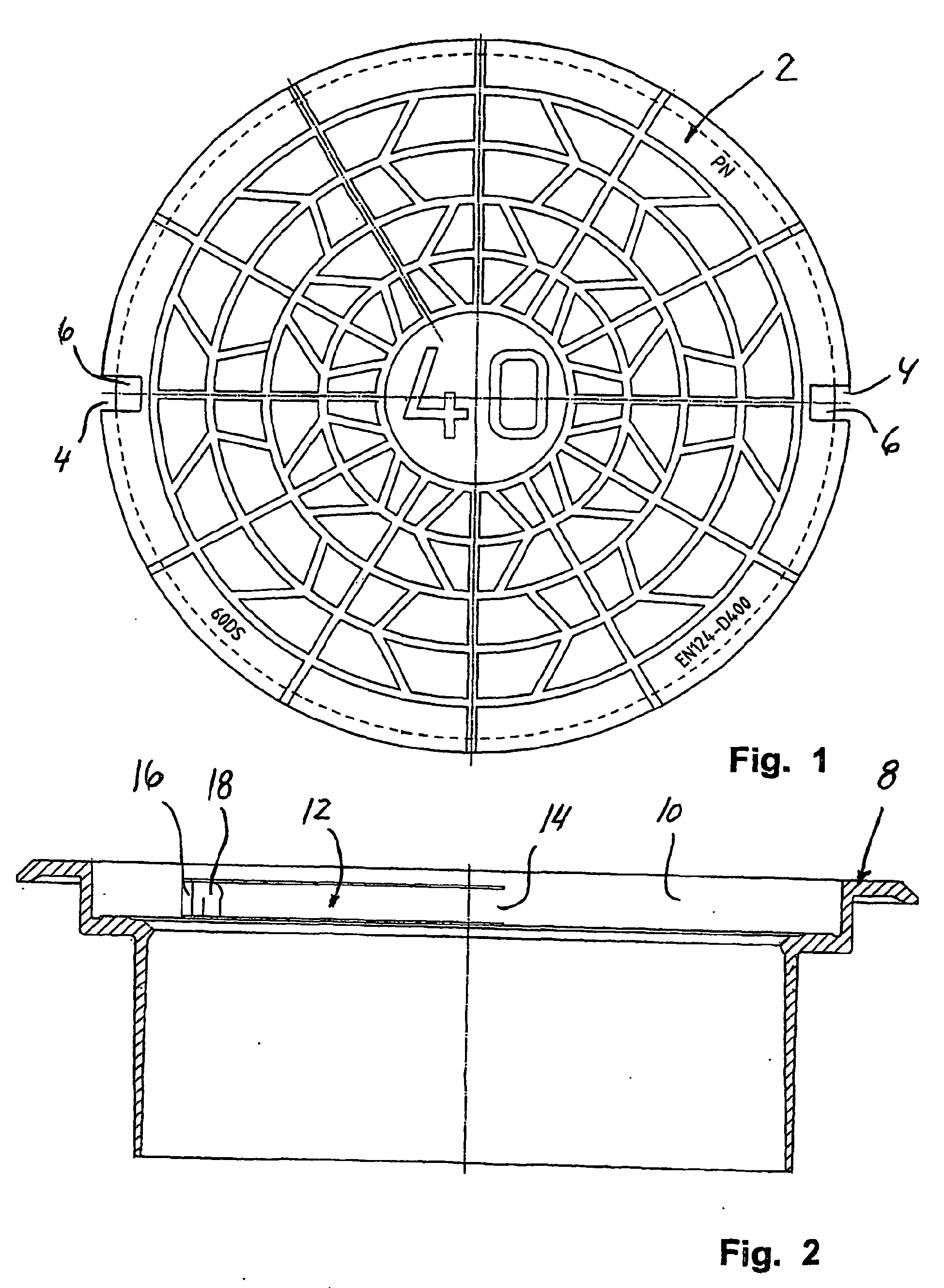
- Fig. 1
- shows a plan view from above of an embodiment of a cover with self-locking function
for a manhole cover frame or manhole according to the invention,
- Fig. 2
- shows a side sectional view of an embodiment of a manhole cover frame with self-locking
function according to the invention,
- Fig. 3
- shows a top view, partly in section, of the manhole cover frame shown in Fig. 2 according
to the invention, and
- Fig. 4
- shows an enlarged part sectional view for illustrating the locking function between
manhole cover frame and manhole cover according to the invention.
[0009] The manhole cover 2 shown in Fig. 1 is provided with two diametrical lateral recesses,
the side profile of which comprising a lower locking surface 6 is more clearly seen
in Fig. 4. An embodiment for a manhole cover frame 8 shown in Fig. 2 and 3 comprises
two horizontal curved, resilient locking arm members 12 in a side wall 10, the arm
members 12 being connected with the side wall 10 at 14, and which at free outer ends
16 are provided with inwardly protruding locking projections 18 which, cf. Fig. 4,
interact with the lower locking surface 6 of the lateral recesses 4 of the cover 2.
[0010] In Fig. 4 is furthermore illustrated how the self-locking locking function between
the manhole cover frame 8 and the cover 2 is easily released by means of an outer
end of an operating lever 20 by pressing back the locking projections 18 so that the
curved, resilient locking arm members 12 are pressed rearwards into a curved cavity
22 behind the locking arm members 12. This cavity 22, which has outer walls 24 and
26 have just the purpose of providing that the function of the resilient locking arm
members 12 is not disturbed by incoming material (stones and sand etc.), why the cavity
22 is only open downwards.
1. A manhole cover frame (8) with self-locking function of the cover (2), the manhole
cover frame comprising a number of resilient locking means being adapted to interact
with complementarily shaped locking means of the cover, characterised in that the said locking means are constituted by a number of approximately horizontal locking
members (12) being formed in a curved internal side wall (10) of the manhole cover
frame, said locking members having the same curvature as said internal side wall,
and in that said locking members (12) are provided at a free outer end (16) with inwardly protruding
locking projections (18), and further in that the frame at the outer side of said locking members and spaced apart therefrom has
a curved outer wall section so that a curved cavity (22) is formed behind the resilient
locking members (12).
2. A manhole cover frame according to claim 1, characterised in that it is formed with two resilient locking members (12) disposed mutually diametrically
opposite.
1. Schachtdeckelrahmen (8) mit Selbstverriegelungsfunktion des Deckels (2), wobei der
Schachtdeckelrahmen eine Zahl von elastischen Arretierungseinrichtungen aufweist,
die für das Zusammenwirken mit komplementär gestalteten Arretierungseinrichtungen
des Deckels vorgesehen sind, dadurch gekennzeichnet, dass die Arretierungseinrichtungen durch eine Zahl von annähernd horizontalen Arretierungselementen
(12) gebildet sind, die in einer gekrümmten Innenseitenwand (10) des Schachtdeckelrahmens
gebildet sind, wobei die Arretierungselemente dieselbe Krümmung wie die innere Seitenwand
aufweisen, und dass die Arretierungselemente (12) an einem freien äußeren Ende (16)
mit nach innen vorstehenden Arretierungsanformungen (18) versehen sind, und dass weiterhin
der Rahmen an der Außenseite der Arretierungselemente und von diesen beabstandet einen
gekrümmten Außenwandabschnitt derart aufweist, dass ein gekrümmter Hohlraum (22) hinter
den elastischen Arretierungselementen (12) gebildet ist.
2. Schachtdeckelrahmen nach Anspruch 1, dadurch gekennzeichnet, dass er mit zwei elastischen Arretierungselementen (12) gebildet ist, die wechselseitig
diametral gegenüber angeordnet sind.
1. Châssis de couvercle de trou d'homme (8) à fonction de verrouillage automatique du
couvercle (2), le châssis de couvercle de trou d'homme comprenant un nombre de moyens
de verrouillage élastiques étant aptes à entrer en interaction avec des moyens de
verrouillage de forme complémentaire du couvercle, caractérisé en ce que lesdits moyens de verrouillage sont constitués par un nombre d'éléments de verrouillage
(12) sensiblement horizontaux étant formés dans une paroi latérale interne courbe
(10) du châssis de couvercle de trou d'homme, lesdits éléments de verrouillage ayant
la même courbure que ladite paroi latérale interne, et en ce que lesdits éléments de verrouillage (12) sont dotés à une extrémité externe libre (16)
de saillies de verrouillage dépassant vers l'intérieur (18), et en outre en ce que
le châssis, sur le côté externe desdits éléments de verrouillage et avec un espacement
par rapport à ceux-ci, comporte une section de paroi externe courbe de manière qu'une
cavité courbe (22) soit formée derrière les éléments de verrouillage élastiques (12).
2. Châssis de couvercle de trou d'homme selon la revendication 1, caractérisé en ce qu'il est constitué de deux éléments de verrouillage élastiques (12) qui sont diamétralement
opposés.