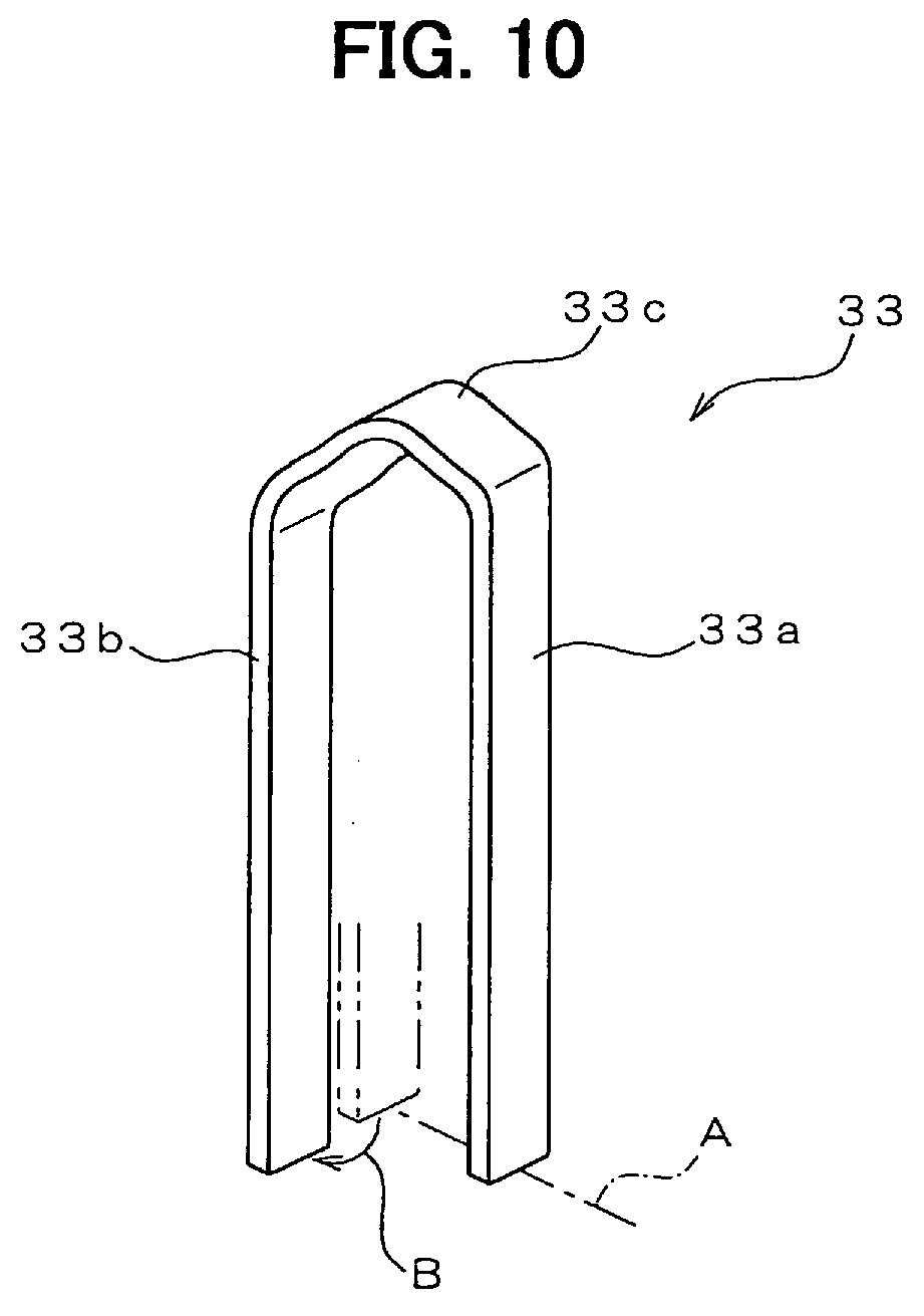
(57) In manufacturing a stator coil (3) for a rotary electric machine (100), a U-shaped
segment (33) is deformed at the turn portion (33c) thereof so that one of two straight
portions (33b) thereof moves against the other straight portion (33a) in a direction
(B) generally perpendicular to a borderline (A) which connects two bordering points
between the straight portions (33a, 33b) and the turn portion (33a). The segment (33)
is twisted by moving the straight portions (33a, 33b) apart from each other. The segment
(33) is inserted into slots (35) formed in a stator core (1) so that the turn portion
(33c) and end portions (331f, 331g, 332f, 332g) of the straight portions (33a, 33b)
protrude from both axial end surfaces of the stator core (1). The end portions (331f,
331g, 332f, 332g) are folded in the circumferential direction of the stator core (1).
The tips (331d, 331e, 332d, 332e) of the end portions (331f, 331g, 332f, 332g) are
connected to tips (331d', 331e', 332d', 332e') of other segments (33).
|
|
