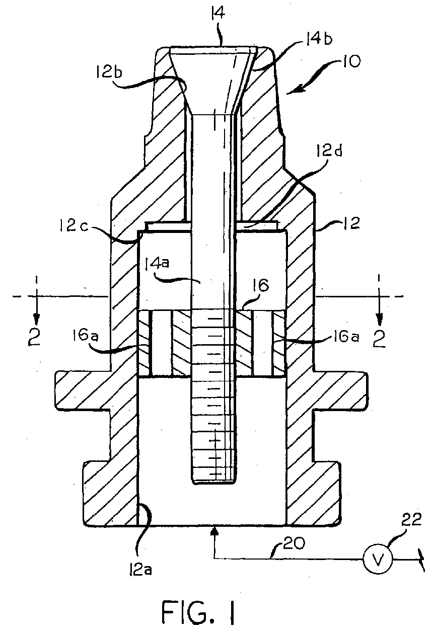
(57) A plunger (10) for intermittently delivery counterblow air to a gob of glass at a
formable temperature in a blank mold of a I.S. glass container forming machine that
is being operated on the blow and blow process. The plunger comprises a fixed annular
member (12) with an enlarged recess (12a) at an inlet end and a valve seat (12d) at
an upper end. The plunger also has a sliding valve member (14) within an annulus of
the annular member (12), and the valve member (14) has a stem portion (14a) and an
enlarged valve seat portion (14b) at a free end thereof. The plunger further has a
collar (16) threadably and adjustably secured to the stem portion of the sliding valve
member, and the collar, which is slidable within the recess of the annular member,
has a plurality of air flow passages (16a) extending therethrough. Pressurized air
is intermittently delivered to the recess of the annular member (12) through an inlet
line (20), which has an on/off valve (22) therein. When the recess of the annular
member (12) is pressurized, pressure therein will act on an underside of the collar
to lift the collar and the valve member, jointly, with respect to the annular member,
and thereby unseat the valve portion of the valve member from the seat of the annular
member. This will permit pressurized air to flow from the recess of the annular member
through the air flow passages in the collar, and then outwardly from the plunger through
a gap between the valve portion of the valve member and the valve seat of the annular
member. Upon the depressurization of the recess of the annular member, the valve member
and the collar will return, by gravity, to a position where the valve portion of the
valve member is seated against the valve seat of the annular member.
|
|
