| (19) |
 |
|
(11) |
EP 1 403 102 B1 |
| (12) |
EUROPEAN PATENT SPECIFICATION |
| (45) |
Mention of the grant of the patent: |
|
08.02.2006 Bulletin 2006/06 |
| (22) |
Date of filing: 22.09.2003 |
|
| (51) |
International Patent Classification (IPC):
|
|
| (54) |
Hitch device for attaching farm implements to a tractor and associated hydraulic circuit
Dreipunktkupplung für Traktoren und zugehörige hydraulische steurung
Attelage pour tracteurs et circuit hydraulique associé
|
| (84) |
Designated Contracting States: |
|
AT BE BG CH CY CZ DE DK EE ES FI FR GB GR HU IE IT LI LU MC NL PT RO SE SI SK TR |
|
Designated Extension States: |
|
AL LT LV MK |
| (30) |
Priority: |
27.09.2002 IT BO20020612
|
| (43) |
Date of publication of application: |
|
31.03.2004 Bulletin 2004/14 |
| (73) |
Proprietor: CNH Italia S.p.A. |
|
41100 Modena (IT) |
|
| (72) |
Inventors: |
|
- Casali, Paolo
41100, Modena (IT)
- Sedoni, Enrico
41100, Modena (IT)
- Brooks, Paul John
41100, Modena (IT)
|
| (74) |
Representative: CNH IP Department |
|
c/o CNH Belgium NV,
Patent Department,
Leon Claeysstraat 3A
8210 Zedelgem
8210 Zedelgem (BE) |
| (56) |
References cited: :
US-A- 3 731 745
US-A- 4 702 489
|
US-A- 3 795 415
US-A1- 2001 007 399
|
|
| |
|
|
|
|
| |
|
| Note: Within nine months from the publication of the mention of the grant of the European
patent, any person may give notice to the European Patent Office of opposition to
the European patent
granted. Notice of opposition shall be filed in a written reasoned statement. It shall
not be deemed to
have been filed until the opposition fee has been paid. (Art. 99(1) European Patent
Convention).
|
[0001] The present invention relates to a hitch device for attaching farm implements to
a tractor.
[0002] More specifically, the present invention relates to a so-called "three-point hitch
device", to which the following description refers purely by way of example.
[0003] In the farm machinery industry, a three-point hitch device is known for attaching
farm implements to a tractor. Such hitch device typically comprises two bottom lift
arms, to which the implement is connected in rotary manner to oscillate about a given
hinge axis and a top actuating cylinder interconnected between the tractor frame and
the implement to control the angular position of the implement about the hinge axis.
[0004] Each lift arm is moved by a further actuating cylinder interposed between the tractor
frame and the lift arm itself. Each cylinder has an output rod defining, inside said
cylinder, two chambers, each of which is connected to a feed line of a hydraulic circuit
supplying pressurized fluid to and from the chambers.
[0005] The hydraulic circuit comprises a slide valve located along the feed lines and movable
selectively between a closed position and three open positions closing and opening
the respective feed lines. In two of the open positions, one of the two feed lines
communicates hydraulically with a pump supplying fluid to the relative chamber, and
the other communicates hydraulically with a fluid tank; and, in the third open position,
both feed lines communicate hydraulically with the tank.
[0006] The hydraulic circuit further comprises a lock valve interposed between the feed
lines and relative chambers to keep the output rod in a given position when the slide
valve is in the closed position.
[0007] A major drawback of known hitch devices of the above type is that, when the slide
valve is moved to the third open position, the lock valve must be operated to connect
both chambers hydraulically to the tank. Moreover, operation of the lock valve is
relatively complex and not very precise.
[0008] It is an object of the present invention to provide a hitch device for attaching
farm implements to a tractor, designed to eliminate the aforementioned drawbacks.
[0009] According to the present invention, there is provided a hitch device for attaching
farm implements to a tractor, the device comprising two lift arms for supporting at
least one farm implement; an actuating cylinder for each lift arm, the actuating cylinder
having an output rod defining two chambers inside the actuating cylinder; and a circuit
for feeding a fluid to and from said chambers; characterized in that said circuit
comprises, for each said chamber, two feed lines for feeding said fluid to and from
the chamber respectively, and also comprises four independent valves; each valve being
located along one of said feed lines, and being movable between a closed position
and at least one open position respectively closing and opening the relative said
feed line.
[0010] A non-limiting embodiment of the present invention will be described by way of example
with reference to the accompanying drawings, in which:
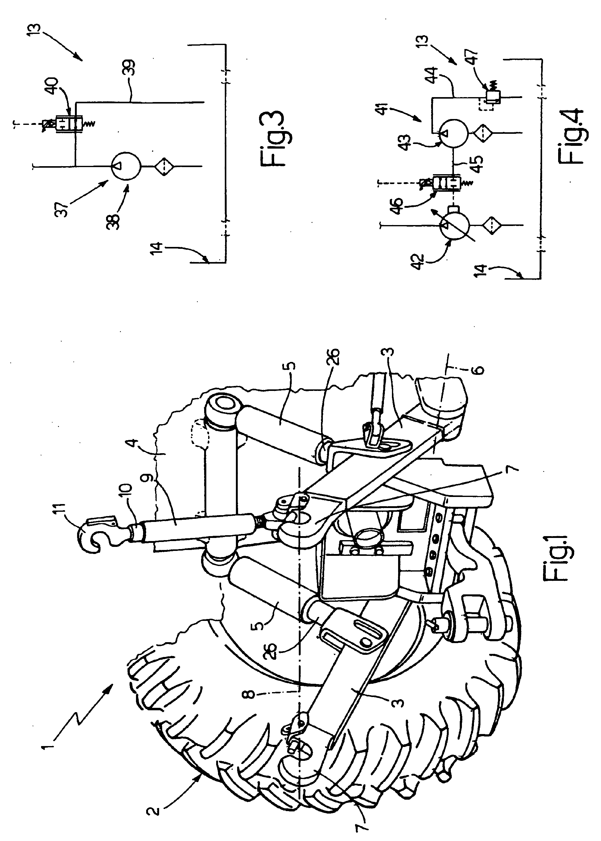
Figure 1 shows a schematic view in perspective of a preferred embodiment of the hitch
device according to the present invention;
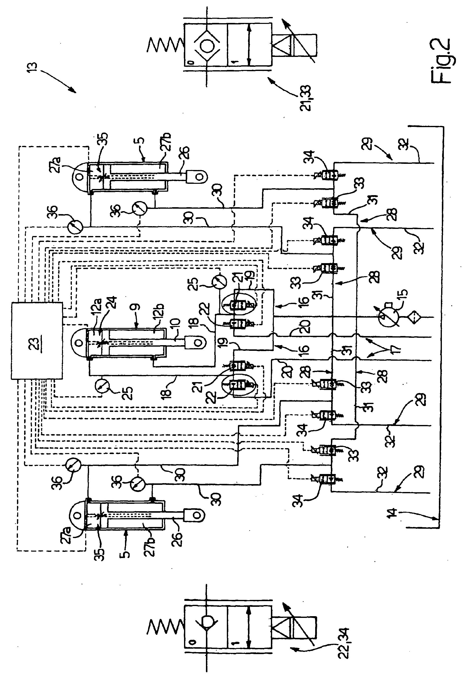
Figure 2 shows schematically, with parts enlarged for clarity, a hydraulic circuit
employed in the Figure 1 hitch device;
Figure 3 shows a first alternative embodiment of the Figure 2 hydraulic circuit; and
Figure 4 shows a second alternative embodiment of the Figure 2 hydraulic circuit.
[0011] Number 1 in Figure 1 indicates as a whole a hitch device for attaching a known farm
implement (not shown), such as a plough, to a tractor 2.
[0012] Device 1 is normally referred to as a "three-point hitch device", and comprises two
bottom lift arms 3, which are connected in rotary manner to a frame 4 of tractor 2
by the interposition, for example, of a spherical joint (not shown). The lift arms
3 are oscillated, with respect to frame 4 and by respective actuating cylinders 5,
about respective substantially horizontal axes 6 of rotation (only one shown in Figure
1).
[0013] The free end of each arm 3 has a supporting hook 7, which co-operates with hook 7
of the other arm 3 to support the implement (not shown). The implement is connected
in rotary manner to the hooks 7 to oscillate, with respect to hooks 7, about a hinge
axis 8. The angular position of the implement about axis 8 is controlled by a top
actuating cylinder 9, which is connected in rotary manner to frame 4 by means of,
for example, a spherical joint (not shown), and comprises an output rod 10, the free
end of which has a supporting hook 11 for engaging the implement.
[0014] With reference to Figure 2, rod 10 defines, inside cylinder 9, two chambers 12, which
communicate hydraulically with a hydraulic circuit 13 supplying pressurized fluid
to the chambers. One of the chambers (hereinafter indicated 12a) has a larger cross
section than the other chamber (hereinafter indicated 12b) as a result of the presence
of the rod 10.
[0015] Circuit 13 comprises a fluid tank 14 and a feed pump 15 - in the example shown, a
known piston pump - for drawing fluid from tank 14. For each chamber 12a, 12b, two
feed lines 16, 17 are provided for feeding fluid respectively to and from chamber
12a, 12b. Lines 16, 17 of each chamber 12a, 12b comprise a portion 18 common to both
lines 16, 17 and connected hydraulically to a respective chamber 12a, 12b and two
respective portions 19, 20. Portion 19 is a feed portion connected hydraulically to
pump 15, and portion 20 is a drain portion connected hydraulically to tank 14.
[0016] Each portion 19, 20 also communicates hydraulically with relative portion 18 through
a proportional electromagnetic valve 21, 22, which is movable, under the control of
an electronic central control unit 23, between a closed position (hereinafter indicated
"O") closing relative portion 19, 20, and an open position (hereinafter indicated
"I") opening relative portion 19, 20.
[0017] In actual use, central control unit 23 selectively controls valves 21, 22 of cylinder
9 independently, so that:
when valves 21, 22 of chamber 12a are in the open "I" and closed "O" position respectively,
and valves 21, 22 of chamber 12b are in the closed "O" and open "I" position respectively,
chamber 12a communicates with the pump 15 and chamber 12b communicates with the tank
14, whereby rod 10 of cylinder 9 moves from a withdrawn position to an extracted position;
when valves 21, 22 of chamber 12a are in the closed "O" and open "I" position respectively,
and valves 21, 22 of chamber 12b are in the open "I" and closed "O" position respectively,
chamber 12a communicates with the tank 14 and chamber 12b communicates with the pump
15, whereby rod 10 of cylinder 9 moves from the extracted position to the withdrawn
position; and
when valves 21, 22 of chamber 12a are in the closed "O" and open "I" position respectively,
and valves 21, 22 of chamber 12b are also in the closed "O" and open "I" position
respectively, both chambers 12a, 12b communicate with tank 14, and rod 10 of cylinder
9 floats as determined by the loads imposed thereon by the farm implement.
[0018] Cylinder 9 further comprises a detecting device 24 connected to the central control
unit 23 for controlling the position of rod 10 along cylinder 9. Two pressure transducers
25 additionally are associated with cylinder 9 and are also connected to central control
unit 23 for determining the pressure in respective chambers 12a, 12b and, therefore,
the force exerted in use on rod 10.
[0019] In actual use, central control unit 23 selectively controls operation of all the
valves 21, 22 of cylinder 9 as a function of the signals from device 24 and/or transducers
25, so as to operate cylinder 9 as follows:
when central control unit 23 only takes into account the signals from device 24, and
excludes the signals from transducers 25, valves 21, 22 of cylinder 9 are operated
to move rod 10 into, and then maintain, a given position stored in central control
unit 23;
when central control unit 23 only takes into account the signals from transducers
25, and excludes the signals from device 24, valves 21, 22 of cylinder 9 are operated
to move rod 10 so that the force exerted on rod 10 by the implement (not shown) is
maintained substantially constant and equal to a given value; and
when central control unit 23 takes into account the signals from both device 24 and
transducers 25, valves 21, 22 of cylinder 9 are operated to move rod 10 within a given
range of positions stored in central control unit 23, and to keep the force exerted
on rod 10 by the implement (not shown) substantially constant and equal to a given
value.
[0020] Each cylinder 5 is connected in rotary manner to frame 4 by the interposition, for
example, of a spherical joint (not shown), and comprises an output rod 26. At its
free end, each rod 26 is connected in articulated manner to a corresponding arm 3.
The rod 26 defines, inside cylinder 5, two chambers 27 communicating hydraulically
with circuit 13. One of the chambers (hereinafter indicated 27a) has a larger cross
section than the other chamber (hereinafter indicated 27b) as a result of the presence
of the rod 26.
[0021] For each chamber 27a, 27b of each cylinder 5, circuit 13 comprises two feed lines
28, 29 for feeding fluid respectively to and from the chamber 27a, 27b. Lines 28,
29 of each chamber 27a, 27b comprise a portion 30 common to both lines 28, 29 and
connected hydraulically to a respective chamber 27a, 27b. The lines 28, 29 further
comprise two respective portions 31, 32, of which portion 31 is a feed portion connected
hydraulically to pump 15, and portion 32 is a drain portion connected hydraulically
to tank 14.
[0022] Each portion 31, 32 also communicates hydraulically with relative portion 30 through
a proportional electromagnetic valve 33, 34, which is movable, under the control of
central control unit 23, between a closed position (hereinafter indicated "O") closing
relative portion 31, 32, and an open position (hereinafter indicated "I") opening
relative portion 31, 32.
[0023] Each cylinder 5 further comprises a detecting device 35 connected to central control
unit 23 for controlling the position of rod 26 along cylinder 5; and two pressure
transducers 36 also connected to central control unit 23 for determining the pressure
in respective chambers 27a, 27b and, therefore, the force exerted in use on rod 26.
[0024] Valves 33, 34 of each cylinder 5 operate in exactly the same way as described for
valves 21, 22 of cylinder 9, and therefore require no further explanation.
[0025] In connection with the above, it should be pointed out that:
- the implement is lowered when the rods 26 are moved simultaneously from the withdrawn
to the extracted position;
- the implement is raised when the rods 26 are moved simultaneously from the extracted
to the withdrawn position;
- the implement is maintained in a given position when the valves 33, 34 of cylinders
5 are all in the closed "O" position;
- the implement is moved about an axis of oscillation (not shown) substantially perpendicular
to axis 8, when one of the rods 26 is maintained in a given position and the other
is moved between the withdrawn and extracted positions, and also when one of the rods
26 is moved from the withdrawn to the extracted position, and the other one from the
extracted to the withdrawn position;
- the implement floats freely relative to the ground when the valves 34 are all in the
open "I" position, and the valves 33 are all in the closed "O" position; and
- the angular position of the implement about axis 8 is controlled selectively by operation
of cylinder 9.
[0026] The Figure 3 embodiment differs from Figure 2 solely by the piston pump 15 being
replaced by a feed assembly 37 comprising a gear pump 38 for drawing fluid from tank
14; a drain line 39 for draining pump 38 into tank 14; and a compensating valve 40,
which is located along line 39, is normally set to an open position opening line 39,
and is moved by central control unit 23 into a closed position closing line 39 when
fluid is to be fed by pump 38 to valves 21 and/or 33.
[0027] The Figure 4 embodiment differs from Figures 2 and 3 solely by piston pump 15 and
feed assembly 37 being replaced by a feed assembly 41 comprising a piston pump 42
for drawing fluid from tank 14; a gear pump 43 also for drawing fluid from tank 14;
a drain line 44 for draining pump 43 into tank 14; and a connecting line 45 connecting
pumps 42 and 43.
[0028] Assembly 41 further comprises a compensating valve 46 located along line 45 and normally
set to a closed position closing line 45; and a drain valve 47 located along line
44 and normally set to an open position opening line 44. In actual use, when fluid
is to be fed by pump 42 to valves 21 and/or 33, central control unit 23 moves valve
46 into an open position opening line 45, so that pump 43 supplies fluid to pump 42,
and valve 47 is moved into a closed position closing line 44.
[0029] The pressure transducers 36 provide for directly controlling the forces exerted,
in use, on hitch device 1, with no need for additional control devices specially designed
for the purpose. In this connection, it should be pointed out that pressure transducers
25 are auxiliary with respect to pressure transducers 36.
1. A hitch device for attaching farm implements to a tractor (2), the device comprising
:
- two lift arms (3) for supporting at least one farm implement;
- an actuating cylinder (5) for each lift arm (3), the actuating cylinder (5) having
an output rod (26) defining two chambers (27a, 27b) inside the actuating cylinder
(5); and
- a circuit (13) for feeding a fluid to and from said chambers (27a, 27b); and
characterized in that said circuit (13) comprises, for each said chamber (27a, 27b), two feed lines (28,
29) for feeding said fluid to and from the chamber (27a, 27b) respectively, and also
comprises four independent valves (33, 34); each valve (33, 34) being located along
one of said feed lines (28, 29), and being movable between a closed position and at
least one open position respectively closing and opening the relative said feed line
(28, 29).
2. A device according to claim 1, characterized in that each said valve (33, 34) is a proportional electromagnetic valve.
3. A device according to claim 1 or 2, characterized in that said actuating cylinder (5) has a first detecting device (36) for detecting a fluid
pressure inside each of said chambers (27a, 27b) to determine a force exerted, in
use, on said output rod (26); electronic control means (23) being provided to selectively
control said valves (33, 34) as a function of a signal from said first detecting device
(36).
4. A device according to any of the preceding claims, characterized in that said actuating cylinder (5) has a second detecting device (35) for detecting a position
of said output rod (26) along the actuating cylinder (5); electronic control means
(23) being provided to selectively control said valves (33, 34) as a function of a
signal from said second detecting device (35).
5. A device according to any of the preceding claims, characterized in that said actuating cylinder (5) has a first detecting device (36) for detecting a fluid
pressure inside each of said chambers (27a, 27b) to determine a force exerted, in
use, on said output rod (26) and a second detecting device (35) for detecting a position
of said output rod (26) along the actuating cylinder (5); electronic control means
(23) being provided to selectively control said valves (33, 34) as a function of a
signal from said first and/or said second detecting device (36, 35).
6. A device according to any of the preceding claims, characterized in that said farm implement is connected in rotary manner to said lift arms (3) to oscillate
about a given hinge axis (8); a further actuating cylinder (9) being interposed between
the tractor (2) and the farm implement to selectively control an angular position
of the farm implement about said hinge axis (8).
7. A device according to claim 6, characterized in that said further actuating cylinder (9) comprises a further output rod (10) defining
two further chambers (12a, 12b) inside the further actuating cylinder (9); said circuit
(13) also comprising two further feed lines (16, 17) for feeding said fluid to and
from each said further chamber (12a, 12b) respectively, and four independent further
valves (21, 22), each located along one of said further feed lines (16, 17) and movable
between a closed position and at least one open position respectively closing and
opening the respective said further feed line (16, 17).
8. A device according to claim 7, characterized in that each said further valve (21, 22) is a proportional electromagnetic valve.
9. A device according to claim 7 or 8, characterized in that said further actuating cylinder (9) has a third detecting device (25) for detecting
a fluid pressure inside each of said further chambers (12a, 12b) to determine a force
exerted, in use, on said further output rod (10); electronic control means (23) being
provided to selectively control said further valves (21, 22) as a function of a signal
from said third detecting device (25).
10. A device according to any of the claims 7 to 9, characterized in that said further actuating cylinder (9) has a fourth detecting device (24) for detecting
a position of said further output rod (10) along the further actuating cylinder (9);
electronic control means (23) being provided to selectively control said further valves
(21, 22) as a function of a signal from said fourth detecting device (24).
11. A device according to any of the claims 7 to 10, characterized in that said further actuating cylinder (9) has a third detecting device (25) for detecting
a fluid pressure inside each of said further chambers (12a, 12b) to determine a force
exerted, in use, on said further output rod (10) and a fourth detecting device (24)
for detecting a position of said further output rod (10) along the further actuating
cylinder (9); electronic control means (23) being provided to selectively control
said further valves (21, 22) as a function of a signal from said third and/or said
fourth detecting device (25, 24).
12. A device according to any of the preceding claims, characterized in that said circuit (13) comprises a piston pump (15).
13. A device according to any of the claims 1 to 11, characterized in that said circuit (13) comprises a feed assembly (37), in turn comprising a tank (14)
for said fluid; a gear pump (38) for drawing fluid from said tank (14); a drain line
(39) for draining the gear pump (38) into the tank (14); and a compensating valve
(40) located along said drain line (39) and movable between an open position and a
closed position respectively opening and closing the drain line (39).
14. A device according to any of the claims 1 to 11, characterized in that said circuit (13) comprises a feed assembly (41), in turn comprising a tank (14)
for said fluid; a piston pump (42) and a gear pump (43) for drawing fluid from said
tank (14); a drain line (44) for draining the gear pump (43) into the tank (14); a
drain valve (47) located along said drain line (44) and movable between an open position
and a closed position respectively opening and closing the drain line (44); a connecting
line (45) connecting said piston pump and said gear pump (42, 43); and a compensating
valve (46) located along said connecting line (45) and movable between an open position
and a closed position respectively opening and closing the connecting line (45).
1. Anhängevorrichtung zum Anhängen von landwirtschaftlichen Arbeitsgeräten an einen Traktor
(2), wobei die Vorrichtung folgendes umfasst:
- zwei Hubarme (3) zur Halterung von zumindest einem landwirtschaftlichen Arbeitsgerät;
- einen Betätigungszylinder (5) für jeden Hubarm (3), wobei der Betätigungszylinder
(5) eine Ausgangs-Kolbenstange (26) aufweist, die zwei Kammern (27a, 27b) im Inneren
des Betätigungszylinders (5) begrenzt; und
- einen Hydraulik-Kreis (13) zum Zuführen einer Hydraulikflüssigkeit zu und von den
Kammern (27a, 27b); und
dadurch gekennzeichnet, dass der Hydraulik-Kreis (13) für jede Kammer (27a, 27b) zwei Speiseleitungen (28, 29)
zum Zuführen der Hydraulikflüssigkeit zu bzw. von der Kammer (27a, 27b) umfasst, und
weiterhin vier unabhängige Ventile (33, 34) umfasst, wobei jedes Ventil (33, 34) entlang
einer der Speiseleitungen (28, 29) angeordnet und zwischen einer geschlossenen Stellung
und zumindest einer offenen Stellung beweglich ist, um die jeweilige der Speiseleitungen
(28, 29) zu schließen bzw. zu öffnen.
2. Vorrichtung nach Anspruch 1, dadurch gekennzeichnet, dass jedes der Ventile (33, 34) ein elektromagnetisches Proportional-Ventil ist.
3. Vorrichtung nach Anspruch 1 oder 2, dadurch gekennzeichnet, dass der Betätigungszylinder (5) eine erste Detektoreinrichtung (36) zur Feststellung
eines Strömungsmitteldruckes im Inneren jeder der Kammern (27a, 27b) zur Feststellung
einer Kraft aufweist, die im Gebrauch auf die Ausgangs-Kolbenstange (26) ausgeübt
wird, wobei elektronische Steuereinrichtungen (23) zur selektiven Steuerung der Ventile
(33, 34) als eine Funktion eines Signals von der ersten Detektoreinrichtung vorgesehen
sind.
4. Vorrichtung nach einem der vorhergehenden Ansprüche, dadurch gekennzeichnet, dass der Betätigungszylinder (5) eine zweite Detektoreinrichtung (35) zur Feststellung
einer Position der Ausgangs-Kolbenstange (26) entlang des Betätigungszylinders (5)
aufweist, wobei elektronische Steuereinrichtungen (23) zur selektiven Steuerung der
Ventile (33, 34) als eine Funktion eines Signals von der zweiten Detektoreinrichtung
(35) vorgesehen sind.
5. Vorrichtung nach einem der vorhergehenden Ansprüche, dadurch gekennzeichnet, dass der Betätigungszylinder (5) eine erste Detektoreinrichtung (36) zur Feststellung
eines Strömungsmitteldruckes im Inneren jeder der Kammern (27a, 27b) zur Feststellung
einer Kraft, die im Gebrauch auf die Ausgangs-Kolbenstange (26) ausgeübt wird, und
zweite Detektoreinrichtung (35) zur Feststellung einer Position der Ausgangs-Kolbenstange
(26) entlang des Betätigungszylinders (5) aufweist, wobei elektronische Steuereinrichtungen
(23) zur selektiven Steuerung der Ventile (33, 34) als eine Funktion eines Signals
von der ersten und/oder der zweiten Detektoreinrichtung (36, 35) vorgesehen sind.
6. Vorrichtung nach einem der vorhergehenden Ansprüche, dadurch gekennzeichnet, dass das landwirtschaftliche Arbeitsgerät in drehbarer Weise an den Hubarmen (3) für eine
Schwingung um eine vorgegebene Gelenkachse (8) angeschlossen ist, und dass ein weiterer
Betätigungszylinder (9) zwischen dem Traktor (2) und dem landwirtschaftlichen Arbeitsgerät
eingefügt ist, um selektiv die Winkelstellung des landwirtschaftlichen Arbeitsgerätes
um die Gelenkachse (8) zu steuern.
7. Vorrichtung nach Anspruch 6, dadurch gekennzeichnet, dass der weitere Betätigungszylinder (9) eine weitere Ausgangs-Kolbenstange (10) umfasst,
die zwei weitere Kammern (12a, 12b) im Inneren des weiteren Betätigungszylinders (9)
begrenzt, dass der Hydraulik-Kreis (13) weiterhin zwei weitere Speiseleitungen (16.
17) zur Zuführung des Strömungsmittels zu bzw. von jeder der weiteren Kammern (12a,
12b) und vier unabhängige weitere Ventile (21, 22) umfasst, die jeweils entlang einer
der weiteren Speiseleitungen (16, 17) angeordnet und zwischen einer geschlossenen
Stellung und zumindest einer offenen Stellung beweglich sind, in der sie die jeweilige
der weiteren Speiseleitungen (16, 17) schließen bzw. öffnen.
8. Vorrichtung nach Anspruch 7, dadurch gekennzeichnet, dass jedes der weiteren Ventile (21, 22) ein elektromagnetisches Proportional-Ventil ist.
9. Vorrichtung nach Anspruch 7 oder 8, dadurch gekennzeichnet, dass der weitere Betätigungszylinder (9) eine dritte Detektoreinrichtung (25) zur Feststellung
eines Strömungsmitteldruckes im Inneren jeder der weiteren Kammern (12a, 12b) aufweist,
um eine Kraft, die im Gebrauch auf die weitere Ausgangs-Kolbenstange (10) ausgeübt
wird, zu bestimmen, wobei elektronische Steuereinrichtungen (23) zur selektiven Steuerung
der weiteren Ventile (21, 22) als eine Funktion eines Signals von der dritten Detektoreinrichtung
(25) vorgesehen sind.
10. Vorrichtung nach einem der Ansprüche 7 bis 9, dadurch gekennzeichnet, dass der weitere Betätigungszylinder (9) eine vierte Detektoreinrichtung (24) zur Feststellung
einer Position der weiteren Ausgangs-Kolbenstange (10) entlang des weiteren Betätigungszylinders
(9) aufweist, wobei elektronische Steuereinrichtungen (23) zur selektiven Steuerung
der weiteren Ventile (21, 22) als eine Funktion eines Signals von der vierten Detektoreinrichtung
(24) vorgesehen sind.
11. Vorrichtung nach einem der Ansprüche 7 bis 10, dadurch gekennzeichnet, dass der weitere Betätigungszylinder (9) eine dritte Detektoreinrichtung (25) zur Feststellung
eines Strömungsmitteldruckes im Inneren jeder der weiteren Kammern (12a, 12b) zur
Feststellung einer Kraft, die im Gebrauch auf die weitere Ausgangs-Kolbenstange(10)
ausgeübt wird, und eine vierte Detektoreinrichtung (24) zur Feststellung einer Position
der weiteren Ausgangs-Kolbenstange (10) entlang des weiteren Betätigungszylinders
(9) aufweist, wobei elektronische Steuereinrichtungen (23) zur selektiven Steuerung
der weiteren Ventile (21, 22) als eine Funktion eines Signals von der dritten und/oder
der vierten Detektoreinrichtung (25, 24) vorgesehen sind.
12. Vorrichtung nach einem der vorhergehenden Ansprüche, dadurch gekennzeichnet, dass der Hydraulik-Kreis (13) eine Kolbenpumpe (15) umfasst.
13. Vorrichtung nach einem der Ansprüche 1 bis 11, dadurch gekennzeichnet, dass der Hydraulik-Kreis (13) eine Speisebaugruppe (37) umfasst, die ihrerseits einen
Tank (14) für das Strömungsmittel; eine Zahnradpumpe (38) zum Ansaugen von Strömungsmittel
von dem Tank (14); eine Ablassleitung (39) zur Entlastung der Zahnradpumpe (38) in
den Tank (14) und ein Kompensationsventil (40) umfasst, das entlang der Ablassleitung
(29) angeordnet und zwischen einer offenen Stellung und einer geschlossenen Stellung
beweglich ist, in der die Ablassleitung (39) geöffnet bzw. geschlossen ist.
14. Vorrichtung nach einem der Ansprüche 1 bis 11, dadurch gekennzeichnet, dass der Hydraulikkreis (13) eine Speisebaugruppe (41) umfasst, die ihrerseits einen Tank
(14) für das Strömungsmittel; eine Kolbenpumpe (42) und eine Zahnradpumpe (43) zum
Ansaugen von Strömungsmittel von dem Tank (14); eine Ablassleitung (44) zur Entlastung
der Zahnradpumpe (43) in den Tank (14); ein Ablassventil (47), das entlang der Ablassleitung
(44) angeordnet und zwischen einer offenen Stellung und einer geschlossenen Stellung
beweglich ist, in der die Ablassleitung (44) geöffnet bzw. geschlossen wird; eine
Verbindungsleitung (45), die die Kolbenpumpe und die Zahnradpumpe (42, 43) verbindet;
und ein Kompensationsventil (46) umfasst, das entlang der Verbindungsleitung (45)
angeordnet ist und zwischen einer offenen Stellung und einer geschlossenen Stellung
beweglich ist, in der die Verbindungsleitung (45) geöffnet bzw. geschlossen wird.
1. Dispositif d'attelage pour la fixation d'outils agricoles à un tracteur (2), l'outil
comprenant :
- deux bras de levage pour supporter au moins un outil agricole ;
- un cylindre d'actionnement (5) pour chaque bras de levage (3), le cylindre d'actionnement
(5) possédant une tige de sortie (26) définissant deux chambres (27a, 27b) à l'intérieur
du cylindre d'actionnement (5); et
- un circuit (13) pour l'alimentation d'un liquide vers lesdites chambres (27a, 27b)
et depuis celles-ci ; et
caractérisé en ce que ledit circuit (13) comprend, pour chacune desdites chambres (27a, 27b), deux conduites
d'alimentation (28, 29) pour l'alimentation dudit liquide à la chambre (27a, 27b)
et depuis celle-ci, respectivement, et comprend également quatre vannes indépendantes
(33, 24); chaque vanne (33, 34) étant disposée sur l'un desdites conduites d'alimentation
(28, 29) et pouvant être déplacée entre une position fermée et au moins une position
ouverte, fermant et ouvrant respectivement ladite conduite d'alimentation relative
(28, 29).
2. Dispositif selon la revendication 1, caractérisé en ce que chaque dite vanne (33, 34) est une électrovanne proportionnelle.
3. Dispositif selon la revendication 1 ou 2, caractérisé en ce que ledit cylindre d'actionnement (5) présente un premier dispositif de détection (36)
pour la détection d'une pression de liquide à l'intérieur de chacune desdites chambres
(27a, 27b) afin de déterminer une force exercée, pendant l'utilisation, sur ladite
tige de sortie (26) ; des moyens de commande électroniques (23) étant prévus pour
commander sélectivement lesdites vannes (33, 34) en fonction d'un signal provenant
dudit dispositif de détection (36).
4. Dispositif selon l'une quelconque des revendications précédentes, caractérisé en ce que ledit cylindre d'actionnement (5) possède un deuxième dispositif de détection (35)
pour la détection d'une position de ladite tige de sortie (26) sur le cylindre d'actionnement
(5) ; des moyens de commande électroniques (23) étant prévus pour commander sélectivement
lesdites vannes (33, 34) en fonction d'un signal provenant dudit deuxième dispositif
de détection (35).
5. Dispositif selon l'une quelconque des revendications précédentes, caractérisé en ce que ledit cylindre d'actionnement (5) possède un premier dispositif de détection (36)
pour la détection d'une pression de liquide à l'intérieur de chacune desdites chambres
(27a, 27b) afin de déterminer une force exercée, pendant l'utilisation, sur ladite
tige de sortie (26) et un deuxième dispositif de détection (35) pour la détection
d'une position de ladite tige de sortie (26) sur le cylindre d'actionnement (5) ;
des moyens de commande électroniques (23) étant prévus pour commander sélectivement
lesdites vannes (33, 34) en fonction d'un signal provenant dudit premier et/ou dudit
deuxième dispositif(s) de détection (36, 35)
6. Dispositif selon l'une quelconque des revendications précédentes, caractérisé en ce que ledit outil agricole est relié de manière rotative auxdits bras de levage (3) afin
d'osciller sur un axe d'articulation donné (8) ; un autre cylindre d'actionnement
(9) étant inséré entre le tracteur (2) et l'outil agricole pour commander sélectivement
une position angulaire de l'outil agricole sur ledit axe d'articulation (8).
7. Dispositif selon la revendication 6, caractérisé en ce que ledit cylindre d'actionnement (9) comprend une autre tige de sortie (10) définissant
deux autres chambres (12a, 12b) à l'intérieur de l'autre cylindre d'actionnement (9)
; ledit circuit (13) comprenant également deux autres conduites d'alimentation (16,
19) pour l'alimentation dudit liquide vers chacune desdites chambres (12a, 12b) et
depuis celles-ci, respectivement, et quatre autres vannes indépendantes (21, 22),
dont chacune est située sur lesdites autres conduites d'alimentation (16, 17) et déplaçables
entre une position fermée et au moins une position ouverte fermant et ouvrant ladite
autre conduite d'alimentation correspondante (16, 17), respectivement.
8. Dispositif selon la revendication 7, caractérisé en ce que chacune desdites autres vannes (21, 22) est une électrovanne proportionnelle.
9. Dispositif selon la revendication 7 ou 8, caractérisé en ce que ledit autre cylindre d'actionnement (9) possède un troisième dispositif de détection
(25) pour la détection d'une pression de liquide à l'intérieur de chacune desdites
autres chambres (12a, 12b) afin de déterminer une force exercée, pendant l'utilisation,
sur ladite autre tige de sortie (10) ; des moyens de commande électroniques (23) étant
prévus pour commander sélectivement lesdites autres vannes (21, 22) en fonction d'un
signal provenant dudit troisième dispositif de détection (25) ;
10. Dispositif selon l'une quelconque des revendications 7 à 9, caractérisé en ce que ledit autre cylindre d'actionnement (9) possède un quatrième dispositif de détection
(24) pour la détection d'une position de ladite autre tige de sortie (10) sur l'autre
cylindre d'actionnement (9); des moyens de commande électroniques (23) étant prévus
pour commander sélectivement lesdites autres vannes (21, 22) en fonction d'un signal
provenant dudit quatrième dispositif de détection (24)
11. Dispositif selon l'une quelconque des revendications 7 à 10, caractérisé en ce que ledit autre cylindre d'actionnement (9) possède un troisième dispositif de détection
(25) pour la détection d'une pression de liquide à l'intérieur de chacune desdites
autres chambres (12a, 12b) afin de déterminer une force exercée, pendant l'utilisation,
sur ladite autre tige de sortie (10) et un quatrième dispositif de détection (24)
pour la détection d'une position de ladite autre tige de sortie (10) sur l'autre cylindre
d'actionnement (9) ; des moyens de commande électroniques (23) étant prévus pour commander
sélectivement lesdites autres vannes (21, 22) en fonction d'un signal provenant dudit
troisième et/ou dudit quatrième dispositifs de détection (25, 24).
12. Dispositif selon l'une quelconque des revendications précédentes, caractérisé en ce que ledit circuit (13) comprend une pompe à piston (15).
13. Dispositif selon l'une quelconque des revendications 1 à 11, caractérisé en ce que ledit circuit (13) comprend un ensemble d'alimentation (37), comprenant à son tour
un réservoir (14) pour ledit liquide ; une pompe à engrenages (38) pour extraire du
liquide dudit réservoir (14) ; une conduite d'évacuation (39) pour évacuer la pompe
à engrenages (38) dans le réservoir (14) ; et une vanne de compensation (40) située
sur ladite conduite d'évacuation (39) et déplaçable entre une position ouverte et
une position fermée ouvrant et fermant respectivement la conduite d'évacuation (39).
14. Dispositif selon l'une quelconque des revendications 1 à 11, caractérisé en ce que ledit circuit (13) comprend un ensemble d'alimentation (41) comprenant à son tour
un réservoir (14) pour ledit liquide ; une pompe à piston (42) et une pompe à engrenages
(43) pour extraire du liquide dudit réservoir (14) ; une conduite d'évacuation (44)
pour l'évacuation de la pompe à engrenages (43) dans le réservoir (14) ; une vanne
d'évacuation (40) située sur ladite conduite d'évacuation (44) et déplaçable entre
une position ouverte et une position fermée, ouvrant et fermant respectivement la
conduite d'évacuation (44) ; une ligne de liaison (45) reliant ladite pompe à piston
et ladite pompe à engrenages (42, 43) ; et une vanne de compensation (46) située sur
ladite conduite de liaison (45) et déplaçable entre une position ouverte et une positon
fermée, ouvrant et fermant respectivement la conduite de liaison (45).