| (19) |
 |
|
(11) |
EP 1 226 334 B1 |
| (12) |
EUROPEAN PATENT SPECIFICATION |
| (45) |
Mention of the grant of the patent: |
|
08.03.2006 Bulletin 2006/10 |
| (22) |
Date of filing: 13.10.2000 |
|
| (51) |
International Patent Classification (IPC):
|
| (86) |
International application number: |
|
PCT/SE2000/001985 |
| (87) |
International publication number: |
|
WO 2001/033043 (10.05.2001 Gazette 2001/19) |
|
| (54) |
METHOD AND DEVICE OF CONTROLLING A ROCK DRILLING MACHINE
VERFAHREN UND VORRICHTUNG ZUM STEUERN EINER ERDBOHRMASCHINE
PROCEDE ET DISPOSITIF DE COMMANDE D'UNE PERFORATRICE DE ROCHES
|
| (84) |
Designated Contracting States: |
|
AT BE CH CY DE DK ES FI FR GB GR IE IT LI LU MC NL PT SE |
| (30) |
Priority: |
03.11.1999 SE 9903974
|
| (43) |
Date of publication of application: |
|
31.07.2002 Bulletin 2002/31 |
| (73) |
Proprietor: Atlas Copco Rock Drills AB |
|
701 91 Örebro (SE) |
|
| (72) |
Inventor: |
|
- EKLÖF, Ake
S-127 36 Skärholmen (SE)
|
| (74) |
Representative: Jansson, Margareta Karin et al |
|
Atlas Copco Rock Drills AB,
Patents
701 91 Örebro
701 91 Örebro (SE) |
| (56) |
References cited: :
US-A- 3 979 944
US-A- 4 356 871
|
US-A- 4 023 626
US-A- 4 440 236
|
|
| |
|
|
|
|
| |
|
| Note: Within nine months from the publication of the mention of the grant of the European
patent, any person may give notice to the European Patent Office of opposition to
the European patent
granted. Notice of opposition shall be filed in a written reasoned statement. It shall
not be deemed to
have been filed until the opposition fee has been paid. (Art. 99(1) European Patent
Convention).
|
[0001] The present invention relates to a method and a device for controlling a rock drilling
machine where the rock drilling machine comprises an impact device for exerting a
drilling tool for impacts, a rotation motor for rotating the drilling tool and a feed
motor for feeding the drilling tool toward a ground. The ground can be rock, earth
or other material for which rock drilling machines normally are used.
[0002] In a previously known method the pressure to the rotation motor is kept constant
up to a first predetermined value. This value corresponds, for a given rotation motor,
to a predetermined tightening moment for the thread joints in the drill string. When
this predetermined value is passed the pressure to the feed motor is reduced in order
to keep the pressure to the rotation motor substantially constant. One desires to
keep the braking moment substantially constant in order to keep the thread joints
sufficiently tightened for efficient drilling at the same time as the tightening is
not allowed to be so hard that great difficulties are obtained at subsequent loosening
of the thread joints. If the pressure to the rotation motor in spite of this increases
to a second predetermined value the pressure to the impact device is changed from
full drilling pressure to collaring pressure. This occurs instantaneously. This causes
a risk for jamming since the sudden decrease of the impulse to the impact device causes
an instantaneous increase of the feed force. US 4 023 626 discloses a hydraulic drill
with a feed motor, a rotation motor and an impact unit where the incrase of pressure
ove a predetermined value in the motor circuit causes the power in the impact unit
to be decreased The present invention, which is defined in the subsequent claims,
aims at avoiding the above mentioned jamming problems. This is achieved by controlling
the pressure to the inlet of the impact device inversely proportionally to the pressure
to the inlet of the rotation motor when the pressure to the inlet of the rotation
motor exceeds a second predetermined value.
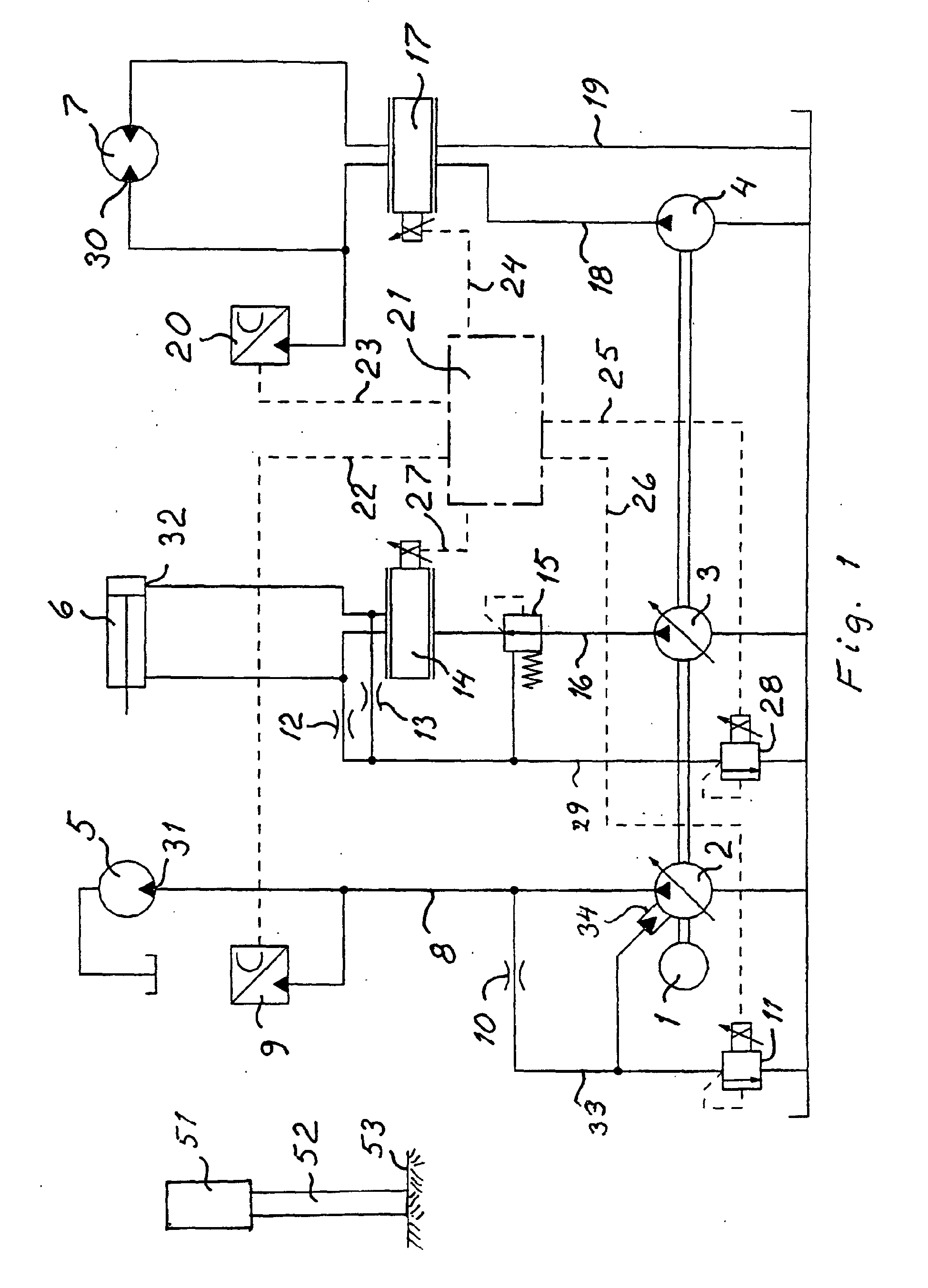
[0003] An embodiment of the invention is described below with reference to the accompnying
drawings in which fig 1 shows a schematic rock drilling machine and a schematic hydraulic
diagram belonging thereto in which the present invention is used. Fig 2 shows an example
of how the impact device pressure varies as a function of the rotation pressure in
a rock drilling machine according to the present invention. The rock drilling machine
51 shown in the drawing comprises a motor 1 which drives a pump 2 with variable displacement,
a pump 3 with variable displacement and a pump 4 with fixed displacement. From pump
2 pressure liquid is led through conduit 8 to the inlet 31 of the impact device 5
of the rock drilling machine 51. A pressure transducer 9 is connected to conduit 8
in order to sense the pressure at the inlet 31. From conduit 8 there is a conduit
33 provided with a restriction 10 and a pressure limiter 11. Pump 2 is provided with
an adjusting means 34 for adjustment of the displacement of pump 2. The adjusting
means 34 is connected to conduit 33. From pump 3 pressure liquid is led through conduit
16 and valve 15 to a proportional directional valve 14 for controlling the feed motor
6 of the rock drilling machine 51. When the proportional directional valve 14 is adjusted
for drilling the pressure liquid is led to the inlet 32 of the feed motor 6. Valve
15 forms together with restrictions 12 and 13 a pressure compensation which is remotely
controlled by the pressure limiter 28 by means of which the feed pressure to the feed
motor 6 of the rock drilling machine 51 is controlled. The pressure limiter 28 is
arranged in a return conduit 29. From pump 4 pressure liquid is led through conduit
18 to a proportional directional valve 17 for controlling the rotation motor 7 of
the rock drilling machine 51. When the proportional directional valve 17 is adjusted
for drilling the pressure liquid is led to the inlet 30 of the rotation motor 7. A
pressure transducer 20 is connected for sensing the pressure at the inlet 30 of the
rotation motor 7. From the proportional directional valve 17 a return conduit 19 leads
to tank. Pressure transducer 9 is by means of a conductor 22 connected to a control
unit 21. Pressure transducer 20 is by means of a conductor 23 connected to the control
unit 21. The proportional directional valve 17 is by means of a conductor 24 connected
to the control unit 21.The pressure limiter 28 is by means of a conductor 25 connected
to the control unit 21. The pressure limiter 11 is by means of a conductor 26 connected
to the control unit 21. The proportional valve 14 is by means of a conductor 27 connected
to the control unit 21.
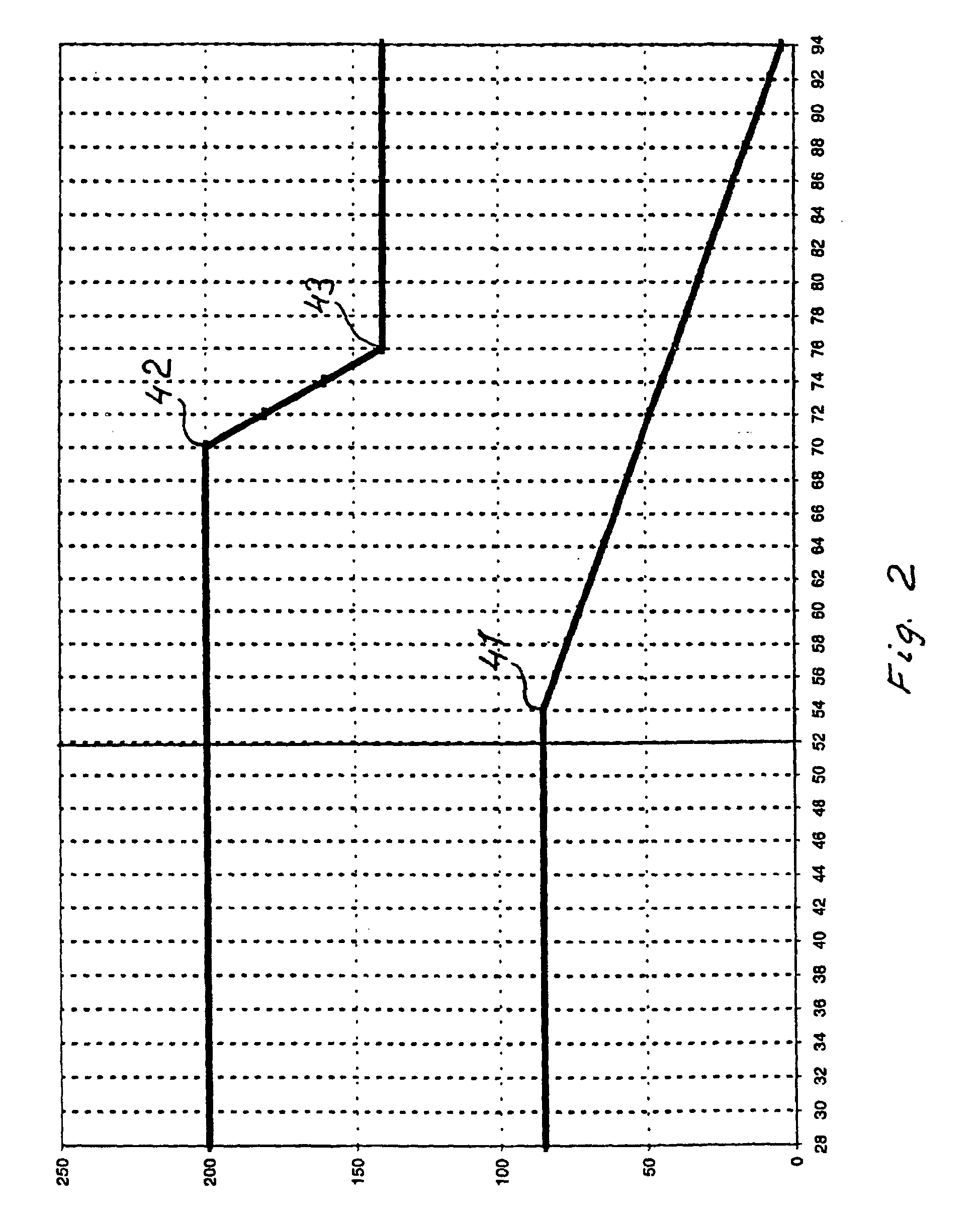
[0004] In the upper part of fig 2 the pressure to the impact device is shown as a function
of the pressure to the rotation motor 7 and in the lower part the pressure to the
feed motor 6 as a function of the pressure to the rotation motor 7. The pressure to
the rotation motor, which corresponds to the braking moment on the drilling tool 52
when this during drilling is fed against the ground 53, is shown on the horizontal
axis. When the drilling tool 52 is fed against the ground 53 the braking moment increases.
As a result the pressure to the rotation motor 7 increases. When this pressure reaches
a first predetermined value 41 the control unit 21 adjusts the proportional pressure
limiter 28 such that the valve 15 decreases the pressure to the inlet 32 of the feed
motor 6 as shown in fig 2. The pressure to the feed motor 6 never decreases to zero
but is maintained at a low pressure so that the rock drilling machine can move forwards
also at low impact device pressure. When the pressure to the rotation motor reaches
a second predetermined value 42 the control unit 21 adjusts the pressure limiter 11
so that the pressure to the impact device 5 is decreased inversely proportionally
to the pressure to the rotation motor 7 as shown in fig 2. This decrease of the pressure
to the impact device 5 continues until the impact device pressure has decreased to
the collaring pressure at 43.
1. Method of controlling a rock drilling machine (51), where the rock drilling machine
comprises an impact device (5) for exerting a drilling tool (52) to impacts, a rotation
motor (7) for rotating the drilling tool (52) and a feed motor (6) for feeding the
drilling tool (52) against a ground (53), comprising sensing (20) the pressure to
an inlet (30) of the rotation motor (7) and reducing the pressure to an inlet (32)
of the feed motor (6) when the pressure to the inlet (30) of the rotation motor exceeds
a first predetermined value (41) in order to keep the pressure to the rotation motor
substantially constant, characterized in that the pressure to an inlet (31) of the impact device (5) is controlled inversely proportionally
to the pressure to the inlet of the rotation motor when this pressure exceeds a second
predetermined value (42).
2. Device for controlling a rock drilling machine (51) comprising an impact device (5)
for exerting a drilling tool (52) to impacts, a rotation motor (7) for rotating the
drilling tool (52), a feed motor (6) for feeding the drilling tool (52) against a
ground (53), means (20) for sensing the pressure to an inlet (30) of the rotation
motor (7) and means (15) for reducing the pressure to an inlet (32) of the feed motor
(6) in response to the means (20) for sensing the pressure to the inlet (30) of the
rotation motor (7) sensing the exceeding of a first predetermined value (41), characterized by means (11) for reducing the pressure to an inlet (31) of the impact device (5) inversely
proportionally to the pressure to the inlet (30) of the rotation motor (7) when the
means (20) for sensing the pressure to the inlet (30) of the rotation motor (7) senses
the exceeding of a second predetermined value (42).
1. Verfahren zur Steuerung einer Gesteinsbohrmaschine (51), wobei die Gesteinsbohrmaschine
eine Schlagvorrichtung (5) für das Ausüben von Schlägen auf ein Bohrwerkzeug (52)
einen Rotationsmotor (7) für das Rotieren des Bohrwerkzeugs (52) und einen Zuführungsmotor
(6) für das Zuführen des Bohrwerkzeugs (52) gegen den Grund (53) umfasst, umfassend
das Messen (20) des Drucks auf einen Einlass (30) des Rotationsmotors (7) und Reduzieren
des Drucks auf einen Einlass (32) des Zuführungsmotors (6), wenn der Druck auf den
Einlass (30) des Rotationsmotors einen ersten, vorgegebenen Wert (41) überschreitet,
um den Druck auf den Rotationsmotor im wesentlichen konstant zu halten, dadurch gekennzeichnet, dass der Druck auf einen Einlass (31) der Schlagvorrichtung (5) umgekehrt proportional
zu dem Druck auf den Einlass des Rotationsmotors gesteuert wird, wenn dieser Druck
einen zweiten, vorgegebenen Wert (42) überschreitet.
2. Vorrichtung für die Steuerung einer Gesteinsbohrmaschine (51) umfassend eine Schlagvorrichtung
(5) für das Ausüben von Schlägen auf ein Bohrwerkzeug (52), einen Rotationsmotor (7)
für das Rotieren des Bohrwerkzeugs (52), einen ZuführungsmotoT (6) für das Zuführen
des Bohrwerkzeugs (52) gegen -den Grund (53) Mittel (20) für das Messen des Drucks
auf einen Einlass (30) des Rotationsmotors (7) und Mittel (15) für das Reduzieren
des Drucks auf einen Einlass (32) des Zuführungsmotors (6) als Antwort auf die Mittel
(20) für das Messen des Drucks auf den Einlass (30) des Rotationsmotors (7), die Überschreiten
eines ersten, vorgegebenen Wertes messen (41), gekennzeichnet durch Mittel (11) für das Reduzieren des Drucks auf einen Einlass (31) der Schlagvorrichtung
(5) umgekehrt proportional zu dem Druck auf den Einlass (30) des Rotationsmotors (7),
wenn die Mittel (20) für das Messen des Drucks auf den Einlass (30) des Rotationsmotors
(7) das Überschreiten einen zweiten, vorgegebenen Wertes (42) messen.
1. Méthode de commande d'une perforatrice de roches (51), où la perforatrice de roches
comprend un dispositif d'impact (5) pour forcer un outil de forage (52) aux impacts,
un moteur de rotation (7) pour la rotation d'un outil de forage (52), et un moteur
d'avance (6) pour conduire l'outil de forage (52) contre le sol (53), comprenant la
détection (20) de la pression à une entrée (30) du moteur de rotation (7) et la réduction
de la pression à une entrée (32) du moteur d'avance (6) lorsque la pression à l'entrée
(30) du moteur de rotation dépasse une première valeur prédéterminée (41) de manière
à maintenir la pression du moteur de rotation essentiellement constante, caractérisée en ce que la pression à une entrée (31) du dispositif d'impact (5) est commandée de façon inversement
proportionnelle à la pression à l'entrée du moteur de rotation lorsque la pression
à l'entrée du moteur de rotation dépasse une deuxième valeur prédéterminée (42).
2. Dispositif de commande d'une perforatrice de roches (51) comprenant un dispositif
d'impact (5) pour forcer un outil de forage (52) aux impacts, un moteur de rotation
(7) pour la rotation d'un outil de forage (52), un moteur d'avance (6) pour conduire
l'outil de forage (52) contre le sol (53), un moyen (20) de détection de la pression
à une entrée (30) d'un moteur de rotation (7), et un moyen (15) de réduction de la
pression à une entrée (32) d'un moteur d'avance (6) par rapport au moyen (20) de détection
de la pression à l'entrée (30) du moteur de rotation (7) afin de détecter le dépassement
d'une première valeur prédéterminée (41), caractérisé par un moyen (11) pour réduire la pression à une entrée (31) du dispositif d'impact (5)
de façon inversement proportionnelle à la pression à l'entrée (30) du moteur de rotation
(7) lorsque le moyen (20) de détection de la pression à l'entrée (30) du moteur de
rotation (7) détecte le dépassement d'une deuxième valeur prédéterminée (42).