| (19) |
 |
|
(11) |
EP 1 309 733 B1 |
| (12) |
EUROPEAN PATENT SPECIFICATION |
| (45) |
Mention of the grant of the patent: |
|
30.05.2007 Bulletin 2007/22 |
| (22) |
Date of filing: 03.07.2001 |
|
| (51) |
International Patent Classification (IPC):
|
| (86) |
International application number: |
|
PCT/US2001/021156 |
| (87) |
International publication number: |
|
WO 2002/014568 (21.02.2002 Gazette 2002/08) |
|
| (54) |
CHROMIUM-CONTAINING CEMENTED CARBIDE BODY HAVING A SURFACE ZONE OF BINDER ENRICHMENT
KÖRPER AUS CHROMHALTIGEM ZEMENTIERTEM KARBID MIT BINDERANGEREICHERTER OBERFLÄCHENZONE
CORPS DE CARBURE CEMENTE CONTENANT DU CHROME PRESENTANT UNE ZONE DE SURFACE ENRICHIE
EN LIANT
|
| (84) |
Designated Contracting States: |
|
AT DE SE |
| (30) |
Priority: |
11.08.2000 US 638048
|
| (43) |
Date of publication of application: |
|
14.05.2003 Bulletin 2003/20 |
| (73) |
Proprietor: KENNAMETAL INC. |
|
Latrobe, PA 15650-0231 (US) |
|
| (72) |
Inventors: |
|
- GRAB, George, P.
Greensburg, PA 15601 (US)
- GREENFIELD, Mark, S.
Greensburg, PA 15601 (US)
- SANTHANAM, Anakkavur, T.
Monroeville, PA 15146 (US)
|
| (74) |
Representative: Sulzbach, Werner |
|
Prinz & Partner GbR
Rundfunkplatz 2
80335 München
80335 München (DE) |
| (56) |
References cited: :
GB-A- 2 095 702
US-A- 5 484 468
US-A- 5 955 186
|
US-A- 5 305 840
US-A- 5 750 247
US-E- R E34 180
|
|
| |
|
|
- PATENT ABSTRACTS OF JAPAN vol. 1997, no. 12, 25 December 1997 (1997-12-25) -& JP 09
207008 A (MITSUBISHI MATERIALS CORP), 12 August 1997 (1997-08-12)
- PATENT ABSTRACTS OF JAPAN vol. 1998, no. 13, 30 November 1998 (1998-11-30) -& JP 10
219384 A (KUROSAKI REFRACT CO LTD), 18 August 1998 (1998-08-18)
- PATENT ABSTRACTS OF JAPAN vol. 2000, no. 02, 29 February 2000 (2000-02-29) -& JP 11
300516 A (MITSUBISHI MATERIALS CORP), 2 November 1999 (1999-11-02)
- PATENT ABSTRACTS OF JAPAN vol. 1999, no. 12, 29 October 1999 (1999-10-29) -& JP 11
197936 A (MITSUBISHI MATERIALS CORP), 27 July 1999 (1999-07-27)
- PATENT ABSTRACTS OF JAPAN vol. 1999, no. 13, 30 November 1999 (1999-11-30) -& JP 11
221708 A (MITSUBISHI MATERIALS CORP), 17 August 1999 (1999-08-17)
- ASTM: "B 276-91 STANDARD TEST FOR APPARENT POROSITY IN CEMENTED CARBIDES" 1996 , AMERICAN
SOCIETY FOR THE TESTING OF METALS , PA,US XP002191392 cited in the application
|
|
| |
|
| Note: Within nine months from the publication of the mention of the grant of the European
patent, any person may give notice to the European Patent Office of opposition to
the European patent
granted. Notice of opposition shall be filed in a written reasoned statement. It shall
not be deemed to
have been filed until the opposition fee has been paid. (Art. 99(1) European Patent
Convention).
|
FIELD OF THE INVENTION
[0001] The invention pertains to a chromium-containing cemented carbide body (e.g., a coated
cemented (cobalt-chromium binder alloy) tungsten carbide cutting insert) that has
a surface zone of binder alloy enrichment.
BACKGROUND OF THE INVENTION
[0002] Coated cemented carbide (e.g., cemented [cobalt] tungsten carbide) cutting inserts
that exhibit a surface zone of binder enrichment are in use for metal cutting applications.
The surface zone of binder enrichment may be stratified such as shown in the article
"The Microstructural Features and Cutting Performance of the High Edge Strength Kennametal
Grade KC850", Proceedings of the Tenth Plansee Seminar, Reutte, Trol, Austria, Metalwerke
Plansee A.G. (1981), pp. 613-627. The surface zone of binder enrichment may be non-stratified
such as shown in U.S. Reissue Patent No. 34,180 to Nemeth et al. or U.S. Patent No.
5,955,186 to Grab.
[0003] Current coated cemented carbide cutting inserts that exhibit a surface zone of binder
enrichment have acceptable performance characteristics. However, it would still be
desirable to provide a coated cemented carbide cutting insert that has improved performance
characteristics.
SUMMARY OF THE INVENTION
[0004] In one form thereof, the invention is a cutting insert according to claim 1.
[0005] The substrate also preferably contains nitrogen as a result of the mechanism used
to obtain binder enrichment.
[0006] Preferably, the tungsten carbide based bulk composition has up to 10 weight percent
tantalum, up to 6 weight percent niobium, and up to 10 weight percent titanium.
[0007] Preferably, there is at least one weight percent total of tantalum, niobium, and
titanium, and more preferably, at least two weight percent total of tantalum, niobium,
and titanium.
[0008] Preferably, the ratio of the weight percent of chromium to the weight percent of
cobalt ranges between 0.05 to 0.10.
[0009] Preferably, the ratio of the weight percent of chromium to the weight percent cobalt
remains about constant between the surface zone of binder alloy enrichment and the
bulk composition.
[0010] Preferably, the cutting insert in accordance with the invention has a substrate composition
as described above and a hard coating thereon composed of one or more layers. Preferably,
the innermost layer contains chromium, which has diffused into the layer from the
substrate during chemical vapor deposition of the coating onto the substrate, preferably
forming a chromium containing solid solution layer (e.g., a titanium chromium carbonitride,
or a titanium tungsten chromium carbonitride).
[0011] These and other aspects of the invention will become more clear upon review of the
following detailed description of the invention in conjunction with the drawings.
BRIEF DESCRIPTION OF THE DRAWINGS
[0012] The following is a brief description of the drawings that form a part of this patent
application:
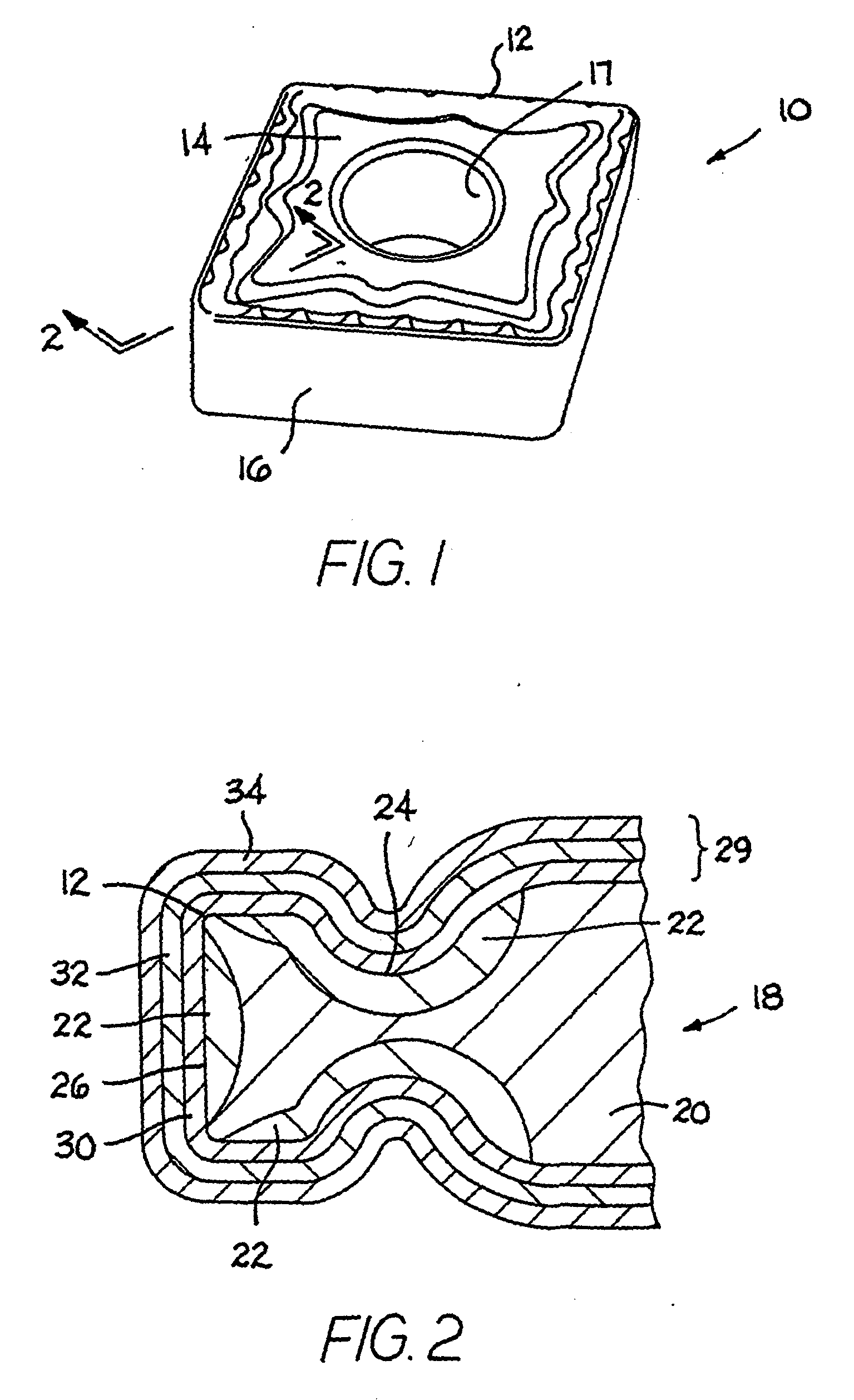
FIG. 1 is an isometric view of a specific embodiment of a cutting insert;
FIG. 2 is a cross-sectional view of the cutting insert of FIG. 1 taken along section
line 2-2 showing a coating scheme that has three layers and a substrate that has a
surface zone of binder enrichment that extends inwardly from both the rake surface
and the flank surface;
FIG. 3 is an isometric view of another specific embodiment of a cutting insert; and
FIG. 4 is a cross-sectional view of the cutting insert of FIG. 3 take along section
3-3 showing a coating scheme that has three layers and a substrate that has a surface
zone of binder enrichment extending inwardly only from the rake surface.
DETAILED DESCRIPTION OF THE INVENTION
[0013] Referring to the drawings, FIGS. 1 and 2 show a CNMG style coated cutting insert
generally designated as 10. Coated cutting insert 10 presents a cutting edge 12 at
the juncture of a rake face 14 and a flank face 16. Cutting insert 10 contains a hole
17.
[0014] The coated cutting insert 10 further includes a substrate generally designated as
18 (se FIG. 2). The substrate 18 has a bulk region 20 and a surface zone of binder
alloy enrichment 22 that has a maximum binder alloy content greater than the binder
alloy content in the bulk region 20 of the substrate. The substrate 18 has a rake
surface 24 and a flank surface 26. In this specific embodiment, the surface zone of
binder alloy enrichment 22 extends inwardly from both the rake surface 24 and the
flank surface 26 of the substrate 18 near the cutting edge 12. The surface zone of
binder alloy enrichment is removed from the other areas of the cutting insert by grinding.
[0015] The substrate 18 comprises a cemented carbide material. One exemplary substrate is
a cemented (cobalt-chromium binder alloy) tungsten carbide that contains one or more
carbide forming elements such as, for example, titanium, tantalum, niobium, zirconium,
and hafnium. The material may also contain vanadium, but the vanadium must be present
along with one or more of the above-identified carbide-forming elements; namely, titanium,
tantalum, niobium, zirconium, and hafnium. The substrate also contains chromium wherein
most, if not all, of the chromium is alloyed with the cobalt to form a cobalt-chromium
binder alloy. Other elements may optionally be a component of the binder alloy wherein
these elements include tungsten, iron, nickel, ruthenium, and rhenium. In some instances,
up to 20 weight percent of the binder alloy may comprise tungsten.
[0016] In the case of a cemented (cobalt-chromium binder alloy) tungsten carbide, the surface
zone of binder alloy enrichment typically exhibits a non-stratified type of binder
alloy enrichment. The porosity of the bulk substrate is typically Type A to Type B
porosity according to ASTM Designation B276-91 (Reapproved 1996). Applicants consider
that the scope of this invention also encompasses a substrate with a surface zone
of non-stratified binder alloy enrichment wherein the bulk substrate has a Type C
porosity according to ASTM Designation B276-91 (Reapproved 1996). U.S. Reissue Patent
No. 34,180 to Nemeth et al. discloses cemented tungsten carbide cutting inserts that
exhibit the non-stratified type of binder enrichment. Pending United States Patent
Application Serial No. 09/534,710 filed on March 24, 2000 and entitled Cemented Carbide
Tool and Method of Making to Liu et al. discloses a substrate with a porosity rating
according to ASTM Designation 8276-91 (Reapproved 1996) of greater than C00, and a
surface zone of non-stratified binder enrichment.
[0017] In addition, applicants consider that the scope of the invention encompasses a substrate
with a surface zone of stratified binder alloy enrichment. The typical substrate with
a surface zone of stratified binder alloy enrichment has a bulk substrate with a Type
C porosity according to ASTM Designation B276-91 (Reapproved 1996). An example of
a substrate with a Type C porosity and a surface zone of stratified binder alloy enrichment
is in the above-mentioned article entitled "The Microstructural Features and Cutting
Performance of the High Edge Strength Kennametal Grade KC850". However, applicants
still contemplate that the scope of the invention may encompass a substrate with a
surface zone of stratified binder enrichment that has a bulk substrate with Type A
and/or Type B porosity according to ASTM Designation B276-91 (Reapproved 1996). The
article to Kobori et al. entitled "Binder Enriched Layer Formed Near the Surface of
Cemented Carbide", Funtai Oyobi Funtai Yakin, Vol. 34, No. 1, pages 129-132 (1987),
describes the stratified type of binder enrichment.
[0018] A range for the components of an exemplary substrate made of cemented (cobalt-chromium
binder alloy) tungsten carbide, i.e., a tungsten carbide-based material, comprises
between 3 weight percent to 12 weight percent cobalt, up to 10 weight percent tantalum,
up to 6 weight percent niobium, up to 10 weight percent titanium, greater than 70
weight percent tungsten and carbon, and a minimum of 0.09 weight percent of chromium.
The upper limit on chromium content is determined by the level at which the substrate
can still avoid toughness problems associated with the specific application in question.
The upper limit for chromium is 15 percent of the cobalt content (e.g., 1.8 w/o chromium
at 12 w/o cobalt; 0.45 w/o chromium at 3 w/o cobalt) or more preferably, 10 percent
of the cobalt content (e.g., 1.2 w/o at 12 w/o cobalt; and 0.3 w/o chromium at 3 w/o
cobalt). The lower limit of chromium content is also dependent on cobalt content and
should be at least 3 percent of the cobalt content (e.g., .09 w/o chromium at 3 w/o
cobalt; and .36 w/o chromium at 12 w/o cobalt, and more preferably, at least 5 percent
of the cobalt content (e.g., 0.15 w/o chromium at 3 w/o cobalt, and 0.6 w/o chromium
at 12 w/o cobalt).
[0019] Another range for the components for an exemplary substrate made of cemented (cobalt-chromium
binder alloy) tungsten carbide comprises between 5 and 6 weight percent cobalt, between
3 and 4 weight percent tantalum, between 1 and 2.5 weight percent titanium, between
0.2 and 0.6 weight percent niobium, chromium present in an amount between 0.2 weight
percent and 0.4 weight, and at least 70 weight percent tungsten and carbon.
[0020] Applicants contemplate that in an exemplary substrate the surface zone of binder
alloy enrichment may extend inwardly from the peripheral surface of the substrate
to a depth of up to about 50 micrometers. In another exemplary substrate, the range
for the depth of binder alloy enrichment is between about 20 and about 30 micrometers.
[0021] In one exemplary substrate, the maximum binder alloy content in the surface zone
of binder alloy enrichment ranges between 125 and 300 weight percent of the binder
content in the bulk substrate. In another exemplary substrate, the maximum binder
alloy content in the surface zone of binder alloy enrichment ranges between 150 weight
percent and 300 weight percent of the binder alloy content in the bulk substrate.
In still another exemplary substrate, the maximum binder alloy content in the surface
zone of binder alloy enrichment ranges between 200 and 300 weight percent of the binder
alloy content in the bulk substrate. In yet another exemplary substrate the binder
alloy content in the surface zone of binder alloy enrichment ranges between 150 and
250 percent of the binder alloy content in the bulk substrate.
[0022] In one exemplary substrate that comprises cemented (cobalt-chromium binder alloy)
tungsten carbide, a specific range for the physical properties is a hardness of between
about 89 and about 93 Rockwell A, a coercive force (H
c) of between 115 and 350 oersteds, and a magnetic saturation between 128 [162 micro
Tesla cubic meter per kilogram cobalt (µT-m
3/kg)] and 160 gauss cubic centimeter per gram cobalt (gauss-cm
3/gm) [202 micro Tesla cubic meter per kilogram cobalt (µT-m
3/kg)]. In another exemplary substrate that comprises cemented (cobalt) tungsten carbide,
a specific range for the physical properties is a bulk hardness of between 91.5 and
92.5 Rockwell A, a coercive force (H
c) of between 155 and 195 oersteds, and a magnetic saturation between 128 gauss cubic
centimeter [162 micro Tesla cubic meter per kilogram cobalt (µT-m
3/kg)] and 160 gauss cubic centimeter per gram cobalt (gauss-cm
3/gm) [202 micro Tesla cubic meter per kilogram cobalt (µT-m
3/kg)].
[0023] As shown in FIGS. 1 and 2, the cutting insert 10 has a coating scheme, generally
designated by brackets 29, that is adherently bonded to the substrate. The coating
scheme 29 includes a base layer 30 next to the substrate 18, a mediate layer 32 next
to the base layer 30, and an outer layer 34 next to the mediate layer 32. Although
this specific embodiment illustrates three layers, applicants contemplate that the
coating scheme may comprise one or more layers.
[0024] As exemplary coating materials the base layer may comprise one or more materials
selected from the group consisting of one or more of the carbides, nitrides, carbonitrides
and oxides of titanium.
[0025] The intermediate layer may comprise one or more materials selected from the group
consisting of titanium carbonitride, titanium nitride, titanium carbide, alumina,
titanium aluminum nitride, zirconium nitride, zirconium carbide, hafnium nitride,
and hafnium carbide.
[0026] The outer layer may comprise one or more materials selected from the group consisting
of titanium carbonitride, titanium nitride, titanium carbide, alumina, titanium aluminum
nitride, titanium diboride, chromium nitride, hafnium nitride, and hafnium carbide.
[0027] Generally speaking, one or more of the coating layers of the coating schemes are
applied by chemical vapor deposition (CVD) and moderate temperature chemical vapor
deposition (MTCVD). However, applicants also contemplate that one or more layers of
a coating scheme may be applied by physical vapor deposition (PVD).
[0028] The substrate may contain a layer eta phase between base coating layer and the substrate.
The layer of eta phase is no thicker than between 2 micrometers to 3 micrometers.
[0029] A cutting insert typically used in turning applications generally presents a surface
zone of binder alloy enrichment that extends inwardly from both the rake surface and
the flank surface of the substrate. Such is the case for the cutting insert illustrated
in FIGS. 1 and 2 wherein, as mentioned hereinabove, FIG. 2 shows that the surface
zone of binder alloy enrichment extends inwardly from both the rake surface and the
flank surface of the substrate.
[0030] There are, however, certain cutting inserts used for certain applications in which
the surface zone of binder alloy enrichment extends inwardly only from the rake surface
of the substrate and any binder alloy enrichment is absent from the other surfaces
of the substrate. In these styles of cutting inserts, the flank surface of the sintered
substrate is typically ground to remove the surface zone of binder alloy enrichment
that extends from the flank surface so as to leave the surface zone of binder alloy
enrichment that extends from the rake surface.
[0031] FIGS. 3 and 4 show a SNG style of coated cutting insert 40 that has a microstructure
in which the surface zone of binder alloy enrichment is present only under the rake
surface. In this regard, cutting insert 40 has four flank faces 42 that intersect
with opposite rake faces 44 to from eight cutting edges 48.
[0032] Cutting insert 40 has substrate generally designated as 49 (see FIG. 4) with a peripheral
rake surface 52 and a peripheral flank surface 54. The substrate 49 has a bulk region
50 that comprises a majority of the substrate 49, and a surface zone of binder alloy
enrichment 56 extends inwardly from the peripheral rake surface 52. Any surface zone
of binder alloy enrichment is absent from the substrate 49 near the peripheral flank
surfaces. Typically, the surface zone of binder alloy enrichment is removed by grinding
from the flank surfaces.
[0033] The substrate 49 of cutting insert 40 may be essentially the same composition and
present the same level of binder enrichment as the substrate 18 of cutting insert
10. Cutting insert 40 has a coating scheme shown in brackets 59 that may be the same
as the coating scheme 29 of cutting insert 10. In this regard, coating scheme 59 presents
a base layer 60, a mediate layer 62 on the base layer 60, and an outer layer 64 on
the mediate layer 62. Additional description of the substrate 49 and the coating scheme
59 is not necessary.
[0034] Coated cutting inserts comprising Substrate No. 1 (as described hereinafter) and
the coating scheme described as follows were subjected to an analysis via transmission
electron microscopy (TEM). This coating scheme comprised: a base layer of titanium
nitride applied to the substrate by CVD to a thickness of 0.5 micrometers, a first
mediate layer of titanium carbonitride applied by MTCVD to the base layer to a thickness
of 4 micrometers, a second mediate layer of alumina applied to the first mediate layer
by CVD to a thickness of 1.5 micrometers, and an outer layer of titanium nitride applied
to the second mediate layer by CVD to a thickness of 0.5 micrometers.
[0035] This TEM analysis revealed that the ratio of the weight percent chromium to the weight
percent of cobalt (wt% chromium/wt% cobalt) was uniform between the surface zone of
cobalt enrichment and the bulk substrate. The composition of the cobalt or binder
alloy phase in the surface zone of enrichment was equal to 4.5 weight percent chromium
and 95.5 weight percent cobalt (or 5 atomic percent chromium and 95 atomic percent
cobalt). Since the weight percent ratio of the starting chromium and cobalt contents
was .3 to 5.75, which is about 5 percent, it appeared that most, if not all, of the
chromium was in the cobalt binder. Applicants would also expect that some tungsten
would be in the binder alloy so that up to 20 weight percent of the binder alloy may
comprise tungsten.
[0036] Even though the base layer comprises titanium nitride or titanium carbonitride, due
to the higher temperature (i.e., 900 to 1000 degrees Centigrade) at which the base
layer is applied, there is believed to be some diffusion of carbon from the substrate
into the base layer so that the titanium nitride changes to titanium carbonitride
or the carbon content of the titanium carbonitride increases. It was surprisingly
discovered that some of the chromium in the substrate diffused into the base layer
so that the base layer is believed to comprise a solid solution titanium-chromium
carbonitride, or a solid solution titanium-tungsten-chromium carbonitride.
[0037] A TEM thin foil was analyzed for chemistry via a Philips CM200 Field Emission Gun
TEM, using the EMi SPEC interface to the EDS system. The results of this analysis
for the metals in the base coating layer is shown below:
| |
w/o |
a/o |
| Ti |
86.48 |
93.29 |
| Cr |
1.91 |
1.90 |
| Co |
2.60 |
2.28 |
| W |
9.0 |
2.53 |
[0038] Applicants believe that the diffusion of chromium into the base layer of the coating
scheme improves the adhesion of the coating to the substrate and the wear resistance
of the coating so as to improve the performance of the cutting insert. TEM analysis
of the base coating layer adjacent to the substrate found that the ratio of the chromium
to the cobalt in the base coating layer was about 1.9/2.3 on an atomic percent basis
with chromium being present in the base layer at about 1.9 atomic percent. This is
surprisingly a significantly higher chromium/cobalt ratio (0.83) than found in the
substrate (approximately 0.05). The inventors believe that to maximize enhanced adhesion
and wear resistance, the ratio of the Cr/Co ratio in the coating to the Cr/Co ratio
in the substrate should preferably be greater than 5, more preferably, greater than
10, and most preferably, greater than 15.
[0039] Coated cutting inserts were made and tested in turning tests and slotted bar tests.
Set forth below is a description of these cutting inserts and the test results.
[0040] Table 1 below presents the composition in weight percent of the elements that comprise
the substrates. In the starting powder mixtures to make Substrates Nos. 1 and 2 nitrogen
is present in the form of titanium nitride. In the starting powder mixture to make
Substrates Nos. 3 and 4 nitrogen is present in the form of titanium carbonitride wherein
the carbon to nitrogen ratio is 1:1. For the starting powder mixtures to make each
one of the Substrates Nos. 1 through 4, the chromium is present in the form of chromium
carbide.
Table 1
| Starting Composition (Weight Percent) of Substrates |
| Substrate |
Cobalt |
Tantalum |
Titanium |
Niobium |
Chromium |
Tungsten, Carbon & Nitrogen |
| No. 1 |
5.75 |
3.3 |
1.80 |
0.40 |
0.30 |
88.45 |
| No. 2 |
5.75 |
3.3 |
1.80 |
0.40 |
None |
88.75 |
| No. 3 |
5.75 |
3.3 |
1.80 |
0.40 |
None |
88.75 |
| No. 4 |
5.75 |
3.3 |
1.80 |
0.40 |
0.30 |
88.45 |
[0041] The above substrates were prepared by conventional powder metallurgical sintering
techniques including ball milling, pressing the powders into a green compact (i.e.,
a consolidated mass of the starting powders), delubing (or dewaxing) the green compact,
and vacuum sintering. For these substrates, the vacuum sintering occurred at a temperature
of about 2700 degrees Fahrenheit (1482 degrees Centigrade) for a duration of about
45 to about 90 minutes. Table 2 below sets forth some of the physical properties of
the sintered substrates.
Table 2
| Physical Properties of Sintered Substrates |
| Substrate |
Coercive Force Hc (Oe) |
MS(gauss cm3/gr Co) |
Thickness of CEZ (µm) |
Hardness (RA) |
Porosity |
| No. 1 |
179 |
131 |
31 |
91.6 |
A02-B00-C00 |
| No. 2 |
163 |
137 |
20 |
91.2 |
A02-B00-C00 |
| No. 3 |
160 |
140 |
41 |
91.9 |
A02-B00-C00 |
| No. 4 |
165 |
143 |
40 |
92.2 |
A02-B00-C00 |
Table 2 presents the coercive force (H
c) in oersteds (Oe), the magnetic saturation (MS) in gauss cubic centimeter per gram
cobalt, the thickness of the surface zone of binder (cobalt) enrichment (CEZ) in micrometers,
the hardness in Rockwell A of the bulk of the substrate, and the porosity of the bulk
substrate as measured by ASTM Designation B 276-91 (Reapproved 1996) entitled "Standard
Test Method for Apparent Porosity in Cemented Carbides".
[0042] Substrates Nos. 1 and 2 were ground top and bottom and honed, and then were coated
with the following coating scheme (Coating Scheme A): a base layer of titanium nitride
applied by chemical vapor deposition (CVD) to a thickness of 0.5 micrometers, a first
mediate layer of titanium carbonitride applied to the base layer by moderate temperature
chemical vapor deposition (MTCVD) to a thickness of 3.5 micrometers, a second mediate
layer of titanium carbonitride applied to the first mediate layer by CVD to a thickness
of 0.5 micrometers, a third mediate layer of alumina (kappa phase) applied to the
second mediate layer by CVD to a thickness of 2.0 micrometers, and an outer layer
of titanium nitride applied by CVD to the third mediate layer to a thickness of 0.5
micrometers.
[0043] Table 3 below sets forth the results in tool life as measured in minutes of four
repetitions of turning tests under the following parameters: a speed equal to 590
surface feet per minute [180 surface meters per minute], a feed equal to 0.010 inches
per revolution (ipr) [0.25 millimeters per revolution], a depth of cut equal to 0.080
inches (2 millimeters), and flood coolant. The workpiece material was a 316Ti stainless
steel bar (German DIN 1.4571). The style of the cutting insert was CNMG432 with a
6 degree positive rake.
Table 3
| Turning (316Ti Stainless Steel) Test Tool Life Results |
| Example (Substrate/Coating) [Presence of Cr] |
Test 1 |
Test 2 |
Test 3 |
Test 4 |
Average [minutes ] |
| No. 1/A [Cr] |
11.7 |
46.6 |
33.1 |
31.9 |
30.8 |
| No. 2/A [no Cr] |
12.0 |
21.9 |
- |
- |
17.0 |
The failure mode for each one of the cutting inserts used in the turning tests reported
in Table 3 was depth of cut notching. The tool life criteria for the turning test
tool life results presented in Table 3 were: uniform flank wear equal to .015 inches
(.38. millimeters); maximum flank wear equal to .030 inches (.76 millimeters); nose
wear equal to .03 inches (.76 millimeters); depth of cut notching equal to .020 inches
(.51 millimeters); crater wear equal to .004 inches (.10 millimeters); and trailing
edge wear equal to .030 inches (.76 millimeters).
[0044] Substrates Nos. 3 and 4 were coating according to the following scheme (Coating Scheme
B): a base layer of titanium nitride applied to the substrate by CVD to a thickness
of 0.5 micrometers, a first mediate layer of titanium carbonitride applied to the
base layer by MTCVD to a thickness of 3.5 micrometers, a second mediate layer of titanium
carbonitride applied to the first mediate layer by CVD to a thickness of 0.5 micrometers,
a third mediate layer of alumina (kappa phase) applied to the second mediate layer
by CVD to a thickness of 2.5 micrometers, and an outer layer of titanium nitride applied
by CVD to the third mediate layer to a thickness of 0.5 micrometers. As described
above, because of the temperature (i.e., 900 to 1000 degrees Centigrade) at which
the base layer was applied, applicants expect that carbon and chromium each diffused
into the base layer of the coating scheme so that the base layer comprised a titanium-chromium
solid solution carbonitride where the carbon and chromium contributions were from
the substrate.
[0045] Table 4 below sets forth the test results in tool life as measured in minutes of
a slotted bar test done at the following parameters: a speed equal to 500 surface
feet per minute (sfm) [152 surface meters per minute], a feed equal to 0.006 inches
per revolution (ipr) [1.5 millimeters per revolution], and a depth of cut equal to
0.100 inches [2.5 millimeters], and flood coolant. The workpiece material was a 304
stainless steel bar (German DIN 1.4301). The style of the cutting insert was CNMG432
with a 6 degree positive rake.
Table 4
| Tool Life [in minutes] from Slotted Bar Tests |
| Example [Substrate/ Coating] |
Test 1 |
Test 2 |
Test 3 |
Test 4 |
Test 5 |
Average [minutes] |
| No. 3/B [no Cr] |
0.7 |
1 |
2.8 |
2.6 |
0.6 |
1.5 |
| No. 4/B [Cr] |
3.7 |
2.7 |
1.4 |
4.2 |
2.6 |
2.9 |
The slotted bar had two diametrically opposed 0.75 inch maximum (1.91 centimeters)
radial slots on a six inch diameter bar. For each one of the cutting inserts used
in the slotted bar test results reported in Table 4, the failure mode was chipping
or fracture of the cutting insert.
[0046] Substrates Nos. 3 and 4 were coated according to the following coating scheme (Coating
Scheme C): a base layer of titanium carbonitride was applied to the substrate by CVD
to a thickness of 2 micrometers, a mediate layer of titanium carbide was applied to
the base layer by CVD to a thickness of 4 micrometers, and an outer layer of alumina
was applied to the mediate layer by CVD to a thickness of 1.5 micrometers. These coated
cutting inserts were then tested in the turning of 316Ti stainless steel under the
following operating parameters: a speed equal to 590 sfm [180 smm], a feed equal to
0.010 ipr [.25 mmpr], and a depth of cut equal to 0.080 inches [2.0 mm]. Table 5 sets
forth the test results as tool life measured in minutes. The style of the cutting
insert was CNMG432 with a 6 degree positive rake.
Table 5
| Tool Life (minutes) of Coated Substrates TC1342 and TC1343 |
| Example [Substrate/Coating] |
Test 1 |
Test 2 |
Test 3 |
Average [minutes] |
| No. 3/C [no Cr] |
14 |
8 |
11 |
11 |
| No. 4/C [Cr} |
24 |
14 |
14 |
17.3 |
The failure mode for each one of the cutting inserts used in the turning tests reported
in Table 5 was depth of cut notching. The tool life criteria for the turning test
tool life results presented in Table 5 were: uniform flank wear equal to .015 inches
(.38 millimeters); maximum flank wear equal to .030 inches (.76 millimeters); nose
wear equal to .03 inches (.76 millimeters); depth of cut notching equal to .020 inches
(.51 millimeters); crater wear equal to .004 inches (.10 millimeters); and trailing
edge wear equal to .030 inches (.76 millimeters).
[0047] Cutting inserts (Style CNMG432 with a 6 degree positive rake) were also tested by
a slotted bar test under the following parameters: a speed equal to 500 surface feet
per minute (sfm) [152 surface meters per minute], a feed equal to 0.006 inches per
revolution (ipr) [0.15 millimeters per revolution], and a depth of cut equal to 0.100
inches [2.5 millimeters], and in which the workpiece material was 304 stainless steel.
Table 6 presents the test results as tool life measured in minutes.
Table 6
| Slotted Bar Test Results of Coated Cutting Inserts |
| Example [Substrate/ Coating] |
Test 1 |
Test 2 |
Test 3 |
Test 4 |
Test 5 |
Average [minutes] |
| No. 3/C [no Cr] |
2 |
4 |
2 |
3 |
4 |
3.0 |
| No. 4/C [Cr] |
4 |
4 |
3 |
6 |
6 |
4.6 |
For each one of the cutting inserts used in the slotted bar test results reported
in Table 6, the failure mode was breakage of the cutting insert.
[0048] These test results show that for the overall turning of 316Ti stainless steel, the
coated cutting inserts that had chromium in the substrate thereof had 181 percent
longer tool life and a 157 percent longer tool life. More specifically, for the coated
cutting inserts having the A coating scheme [Substrates Nos. 1 and 2], the cutting
insert with the substrate containing chromium had 181 percent longer tool life than
the cutting insert with the substrate that did not contain chromium. For the coated
cutting inserts having the C coating scheme [Substrates Nos. 3 and 4], the cutting
insert with the substrate containing chromium had 157 percent longer tool life than
the cutting insert with the substrate that did not contain chromium.
[0049] These test results also show that for the slotted bar test, the coated cutting inserts
that had chromium in the substrate thereof had 193 percent longer tool life and a
153 percent longer tool. More specifically, for the coated cutting inserts having
the B coating scheme [Substrates Nos. 3 and 4], the cutting insert with the substrate
containing chromium had 193 percent longer tool life than the cutting insert with
the substrate that did not contain chromium. For the coated cutting inserts having
the C coating scheme [Substrates Nos. 3 and 4], the cutting insert with the substrate
containing chromium had 153 percent longer tool life than the cutting insert with
the substrate that did not contain chromium.
[0050] Applicants believe that the improvement in the performance by the cutting inserts
that contain chromium is due to the better adhesion of the coating to the substrate.
Applicants believe that the better adhesion is principally due to the diffusion of
the chromium into the base layer during the coating process. The presence of the chromium
in the base layer is consistent with the improvement in the depth of cut notching.
1. A cutting insert (10; 40) comprising:
a substrate (18; 49), the substrate (18; 49) having a composition comprising a tungsten
carbide-based material comprising a bulk composition of at least 70 weight percent
tungsten and carbon, between 3 weight percent and 12 weight percent cobalt, and at
least 0.09 weight percent chromium, wherein the ratio of the weight percent of chromium
to the weight percent of cobalt ranges between 0.03 to 0.15;
the cobalt and the chromium forming a binder alloy; and
the binder alloy content being enriched in a surface zone of binder alloy enrichment
(22; 56) beginning near and extending inwardly from the peripheral surface (24, 26;
52, 54) of the substrate (18; 49).
2. The cutting insert (10; 40) of claim 1 wherein the bulk composition of the substrate
(18; 49) comprises between 0.2 and 0.4 weight percent chromium.
3. The cutting insert (10; 40) of claims 1 or 2 wherein the bulk composition of the substrate
(18; 49) further comprises one or more of titanium, tantalum, niobium, zirconium and
hafnium
4. The cutting insert (10; 40) of claim 3 wherein the bulk composition of the substrate
(18; 49) comprises tantalum in an amount up to 10 weight percent, niobium in an amount
up to 6 weight percent, and titanium in an amount up to about 10 weight percent.
5. The cutting insert (10; 40) of claims 3 or 4 wherein the bulk composition of the substrate
(18; 49) further comprises vanadium.
6. The cutting insert (10; 40) of claim 3 wherein the bulk composition of the substrate
(18; 49) comprises between 5 and 6 weight percent cobalt, between 3 and 4 weight percent
tantalum, between 1 and 2.5 weight percent titanium, and between 0.2 and 0.6 weight
percent niobium.
7. The cutting insert (10; 40) of claim 1 wherein the bulk composition of the substrate
(18; 49) comprises 5.7 weight percent cobalt, 3.3 weight percent tantalum, 1.8 weight
percent titanium, 0.4 weight percent niobium, 0.3 weight percent chromium, and 88.5
weight percent tungsten and carbon.
8. The cutting insert (10; 40) of claim 1 wherein the bulk composition of the substrate
(18; 49) comprises between 0.2 and 0.4 weight percent chromium, one or more of titanium,
tantalum and niobium in a total amount of between 4 and 7 weight percent, and tungsten
and carbon in a total amount of between 85 and 95 weight percent.
9. The cutting insert (10; 40) of anyone of claims 1 to 8 wherein the binder alloy further
includes one or more of tungsten, iron, nickel, ruthenium, and rhenium.
10. The cutting insert (10; 40) of anyone of claims 1 to 9 wherein the ratio of the weight
percent of chromium to the weight percent of the cobalt ranges between 0.05 to 0.10.
11. The cutting insert (10; 40) of anyone of claims 1 to 10 wherein the ratio of the weight
percent of chromium to the weight percent of the cobalt remains about constant between
the surface zone of binder alloy enrichment (22; 56) and the bulk substrate.
12. The cutting insert (10; 40) of anyone of claims 1 to 11 wherein the surface zone of
binder alloy enrichment (22; 56) has a maximum binder alloy content between 125 and
300 percent of the binder alloy content in the bulk substrate.
13. The cutting insert (10; 40) of claim 12 wherein the surface zone of binder alloy enrichment
(22; 56) has a maximum binder alloy content between 200 and 300 percent of the binder
alloy content in the bulk substrate.
14. The cutting insert (10; 40) of claim 12 wherein the surface zone of binder alloy enrichment
(22; 56) has a maximum binder alloy content between 150 percent and 250 percent of
the binder alloy content in the bulk substrate.
15. The cutting insert (10; 40) of anyone of claims 1 to 14 wherein the surface zone of
binder alloy enrichment (22; 56) extends to a depth up to 50 micrometers from the
peripheral surface (24; 26; 52; 54) of the substrate (18; 49).
16. The cutting insert (10; 40) of anyone of claims 1 to 15 wherein the surface zone of
binder alloy enrichment (22; 56) exhibits a non-stratified type of enrichment.
17. The cutting insert (10; 40) of anyone of claims 1 to 15 wherein the surface zone of
binder alloy enrichment (22; 56) exhibits a stratified type of enrichment.
18. The cutting insert (10; 40) of claims 16 or 17 wherein the bulk substrate contains
pores up to 10 micrometers as so to exhibit an apparent porosity of Type A according
to ASTM Designation B276-91 (Reapproved 1996).
19. The cutting insert (10; 40) of claims 16 or 17 wherein the bulk substrate contains
pores in the range from 10 micrometers to 25 micrometers as so to exhibit an apparent
porosity of Type B according to ASTM Designation B276-91 (Reapproved 1996).
20. The cutting insert (10; 40) of claims 16 or 17 wherein the bulk substrate contains
uncombined carbon as so to exhibit an apparent porosity of Type C according to ASTM
Designation B276-91 (Reapproved 1996).
21. The cutting insert (10; 40) of claims 1 to 20 further including a coating (29; 59)
adherently bonded to the substrate (18; 49).
22. The cutting insert (10; 40) of claim 21 wherein the coating (29; 59) includes a base
layer (30; 60) next to the substrate (18; 49), and the base layer (30; 60) contains
chromium.
23. The cutting insert (10; 40) of claim 22 wherein the chromium in the base layer (30;
60) is diffused from the substrate (18; 49) during the application of the coating
(29; 59).
24. The cutting insert (10; 40) of claim 22 or 23 wherein the components of the base layer
(30; 60) applied to the substrate (18; 49) comprise titanium and nitrogen.
25. The cutting insert (10; 40) of claim 24 wherein the base layer (30; 60) includes a
solid solution containing titanium, chromium and nitrogen.
26. The cutting insert (10; 40) of claim 25 wherein the components of the base layer (30;
60) applied to the substrate (18; 49) further comprise carbon.
27. The cutting insert (10; 40) of claim 25 wherein the base layer (30; 60) further includes
carbon, and the base layer (30; 60) including a solid solution of titanium, chromium,
carbon and nitrogen.
28. The cutting insert (10; 40) of claim 27 wherein the carbon in the base layer (30;
60) is diffused from the substrate (18; 49) during the application of the coating
(29; 59).
29. The cutting insert (10; 40) of claim 22 or 23 wherein the base layer (30; 60) comprises
titanium and one or more elements selected from the group consisting of carbon, nitrogen
and oxygen.
30. The cutting insert (10; 40) of anyone of claims 22 to 29 wherein the coating (29;
59) further including another layer (32; 62) applied to the surface of the base layer
(30; 60).
31. The cutting insert (10; 40) of anyone of claims 1 to 30 wherein the bulk substrate
having a hardness of between 89 and 93 Rockwell A, a coercive force (Hc) of between 115 and 350 oersteds, and a magnetic saturation between 128 and 160 gauss
cubic centimetre per gram cobalt.
32. The cutting insert (10; 40) of anyone of claims 22 to 31 wherein the coating (29;
59) further includes a mediate layer (32; 62) applied to the base layer (30; 60),
and the mediate layer selected from the group consisting of titanium carbonitride,
titanium nitride, titanium carbide, alumina, titanium aluminium nitride, hafnium carbide,
hafnium nitride, zirconium carbide, and zirconium nitride.
33. The cutting insert (10; 40) of claim 32 wherein the coating (29; 59) further includes
an outer layer (34; 64), and the outer layer comprises one or more materials selected
from the group consisting of titanium carbonitride, titanium nitride, titanium carbide,
alumina, titanium aluminium nitride, titanium diboride, chromium nitride, hafnium
nitride, and hafnium carbide.
34. The cutting insert (10; 40) of anyone of claims 21 to 33 wherein the coating (29;
59) comprises one or more layers applied by one or more of physical vapor deposition,
chemical vapor deposition and moderate temperature chemical vapor deposition.
35. The cutting insert (10; 40) of claim 22 wherein the base layer (30; 60) comprises
titanium nitride applied to the substrate (18; 49) by chemical vapor deposition, and
the coating (29; 59) further includes a first layer of titanium carbonitride applied
to the base layer (30; 60) by moderate temperature chemical vapor deposition, a second
mediate layer of titanium carbonitride applied to the first mediate layer by chemical
vapor deposition, a third mediate layer of alumina applied to the second mediate layer
by chemical vapor deposition, and an outer layer of titanium nitride applied to the
third mediate layer by chemical vapor deposition.
36. The cutting insert (10; 40) of claim 22 wherein the base layer (30; 60) comprises
titanium carbonitride applied to the substrate (18; 49) by chemical vapor deposition,
and the coating (29; 59) further includes a mediate layer of titanium carbide applied
to the base layer (30; 60) by chemical vapor deposition, and an outer layer of alumina
applied to the mediate layer by chemical vapor deposition.
37. The cutting insert (10; 40) of claim 22 wherein the base layer (30; 60) comprises
titanium carbonitride applied to the substrate (18; 49) by chemical vapor deposition,
and the coating (29; 59) further includes a first mediate layer of titanium carbonitride
applied to the base layer (30; 60) by moderate temperature chemical vapor deposition,
a second mediate layer of alumina applied to the first mediate layer by chemical vapor
deposition, and an outer layer of titanium nitride applied to the second mediate layer
by chemical vapor deposition.
38. The cutting insert (10; 40) of anyone of claims 22 to 37 wherein the ratio of the
weight percent of chromium to the weight percent of the cobalt is greater than 0.03.
39. The cutting insert (10; 40) according to anyone of the preceding claims, further comprising
a rake face (14; 44) and a flank face (16; 42), a cutting edge (12; 48) at the juncture
of the rake face and the flank face.
1. Schneideinsatz (10; 40) mit:
einem Substrat (18; 49), wobei das Substrat (18; 49) eine Zusammensetzung aufweist,
die ein Material auf Wolframcarbidbasis umfasst, das eine Massezusammensetzung von
mindestens 70 Gew.-% Wolfram und Kohlenstoff, 3 Gew.-% bis 12 Gew.-% Kobalt und mindestens
0,09 Gew.-% Chrom umfasst, bei dem das Verhältnis der Gewichtsprozente von Chrom zu
Kobalt zwischen 0,03 und 0,15 liegt,
wobei Kobalt und Chrom eine Binderlegierung bilden, und
wobei der Binderlegierungsgehalt in einer Oberflächenzone einer Binderlegierungsanreicherung
(22; 56) angereichert ist, die in der Nähe der peripheren Oberfläche (24, 26; 52,
54) des Substrats (18; 49) beginnt und sich von dort nach innen erstreckt.
2. Schneideinsatz (10; 40) nach Anspruch 1, bei dem die Massezusammensetzung des Substrats
(18; 49) 0,2 bis 0,4 Gew.-% Chrom umfasst.
3. Schneideinsatz (10; 40) nach Anspruch 1 oder 2, bei dem die Massezusammensetzung des
Substrats (18; 49) ferner Titan und/oder Tantal und/oder Niob und/oder Zirconium und/oder
Hafnium umfasst.
4. Schneideinsatz (10; 40) nach Anspruch 3, bei dem die Massezusammensetzung des Substrats
(18; 49) Tantal in einer Menge von bis zu 10 Gew.-%, Niob in einer Menge von bis zu
6 Gew.-% und Titan in einer Menge von bis zu etwa 10 Gew.-% umfasst.
5. Schneideinsatz (10; 40) nach Anspruch 3 oder 4, bei dem die Massezusammensetzung des
Substrats (18; 49) ferner Vanadium umfasst.
6. Schneideinsatz (10; 40) nach Anspruch 3, bei dem die Massezusammensetzung des Substrats
(18; 49) 5 bis 6 Gew.-% Kobalt, 3 bis 4 Gew.-% Tantal, 1 bis 2,5 Gew.-% Titan und
0,2 bis 0,6 Gew.-% Niob umfasst.
7. Schneideinsatz (10; 40) nach Anspruch 1, bei dem die Massezusammensetzung des Substrats
(18; 49) 5,7 Gew.-% Kobalt, 3,3 Gew.-% Tantal, 1,8 Gew.-% Titan, 0,4 Gew.-% Niob,
0,3 Gew.-% Chrom und 88,5 Gew.-% Wolfram und Kohlenstoff umfasst.
8. Schneideinsatz (10; 40) nach Anspruch 1, bei dem die Massezusammensetzung des Substrats
(18; 49) 0,2 bis 0,4 Gew.-% Chrom sowie Titan und/oder Tantal und/oder Niob in einer
Gesamtmenge von 4 bis 7 Gew.-% und Wolfram und Kohlenstoff in einer Gesamtmenge von
85 bis 95 Gew.-% umfasst.
9. Schneideinsatz (10; 40) nach einem der Ansprüche 1 bis 8, bei dem die Binderlegierung
ferner Wolfram und/oder Eisen und/oder Nickel und/oder Ruthenium und/oder Rhenium
einschließt.
10. Schneideinsatz (10; 40) nach einem der Ansprüche 1 bis 9, bei dem das Verhältnis der
Gewichtsprozente von Chrom zu Kobalt zwischen 0,05 und 0,10 liegt.
11. Schneideinsatz (10; 40) nach einem der Ansprüche 1 bis 10, bei dem das Verhältnis
der Gewichtsprozente von Chrom zu Kobalt zwischen der Oberflächenzone der Binderlegierungsanreicherung
(22; 56) und dem Massesubstrat etwa konstant bleibt.
12. Schneideinsatz (10; 40) nach einem der Ansprüche 1 bis 11, bei dem die Oberflächenzone
der Binderlegierungsanreicherung (22; 56) einen maximalen Binderlegierungsgehalt von
125 bis 300 Prozent des Binderlegierungsgehalts in dem Massesubstrat aufweist.
13. Schneideinsatz (10; 40) nach Anspruch 12, bei dem die Oberflächenzone der Binderlegierungsanreicherung
(22; 56) einen maximalen Binderlegierungsgehalt von 200 bis 300 Prozent des Binderlegierungsgehalts
in dem Massesubstrat aufweist.
14. Schneideinsatz (10; 40) nach Anspruch 12, bei dem die Oberflächenzone der Binderlegierungsanreicherung
(22; 56) einen maximalen Binderlegierungsgehalt von 150 Prozent bis 250 Prozent des
Binderlegierungsgehalts in dem Massesubstrat aufweist.
15. Schneideinsatz (10; 40) nach einem der Ansprüche 1 bis 14, bei dem sich die Oberflächenzone
der Binderlegierungsanreicherung (22; 56) bis in eine Tiefe von bis zu 50 Mikrometer
von der peripheren Oberfläche (24, 26; 52, 54) des Substrats (18; 49) aus erstreckt.
16. Schneideinsatz (10; 40) nach einem der Ansprüche 1 bis 15, bei dem die Oberflächenzone
der Binderlegierungsanreicherung (22; 56) eine nicht geschichtete Anreicherungsart
aufweist.
17. Schneideinsatz (10; 40) nach einem der Ansprüche 1 bis 15, bei dem die Oberflächenzone
der Binderlegierungsanreicherung (22; 56) eine geschichtete Anreicherungsart aufweist.
18. Schneideinsatz (10; 40) nach Anspruch 16 oder 17, bei dem das Massesubstrat Poren
von bis zu 10 Mikrometer enthält und so eine scheinbare Porosität vom Typ A gemäß
ASTM-Bezeichnung B276-91 (1996 erneut bestätigt) aufweist.
19. Schneideinsatz (10; 40) nach Anspruch 16 oder 17, bei dem das Massesubstrat Poren
im Bereich von 10 Mikrometer bis 25 Mikrometer enthält und so eine scheinbare Porosität
vom Typ B gemäß ASTM-Bezeichnung B276-91 (1996 erneut bestätigt) aufweist.
20. Schneideinsatz (10; 40) nach Anspruch 16 oder 17, bei dem das Massesubstrat ungebundenen
Kohlenstoff enthält und so eine scheinbare Porosität vom Typ C gemäß ASTM-Bezeichnung
B276-91 (1996 erneut bestätigt) aufweist.
21. Schneideinsatz (10; 40) nach den Ansprüchen 1 bis 20, der ferner eine haftend an das
Substrat (18; 49) gebundene Beschichtung (29; 59) einschließt.
22. Schneideinsatz (10; 40) nach Anspruch 21, bei dem die Beschichtung (29; 59) eine Grundschicht
(30; 60) direkt auf dem Substrat (18; 49) einschließt und die Grundschicht (30; 60)
Chrom enthält.
23. Schneideinsatz (10; 40) nach Anspruch 22, bei dem das Chrom in der Grundschicht (30;
60) während des Aufbringens der Beschichtung (29; 59) aus dem Substrat (18; 49) diffundiert
wird.
24. Schneideinsatz (10; 40) nach Anspruch 22 oder 23, bei dem die Komponenten der auf
das Substrat (18; 49) aufgebrachten Grundschicht (30; 60) Titan und Stickstoff umfassen.
25. Schneideinsatz (10; 40) nach Anspruch 24, bei dem die Grundschicht (30; 60) eine Titan,
Chrom und Stickstoff enthaltende feste Lösung einschließt.
26. Schneideinsatz (10; 40) nach Anspruch 25, bei dem die Komponenten der auf das Substrat
(18; 49) aufgebrachten Grundschicht (30; 60) ferner Kohlenstoff umfassen.
27. Schneideinsatz (10; 40) nach Anspruch 25, bei dem die Grundschicht (30; 60) ferner
Kohlenstoff umfaßt und eine feste Lösung aus Titan, Chrom, Kohlenstoff und Stickstoff
einschließt.
28. Schneideinsatz (10; 40) nach Anspruch 27, bei dem der Kohlenstoff in der Grundschicht
(30; 60) während des Aufbringens der Beschichtung (29; 59) aus dem Substrat (18; 49)
diffundiert wird.
29. Schneideinsatz (10; 40) nach Anspruch 22 oder 23, bei dem die Grundschicht (30; 60)
Titan und eines oder mehrere aus der aus Kohlenstoff, Stickstoff und Sauerstoff bestehenden
Gruppe ausgewählte Elemente umfasst.
30. Schneideinsatz (10; 40) nach einem der Ansprüche 22 bis 29, bei dem die Beschichtung
(29; 59) ferner eine weitere auf die Oberfläche der Grundschicht (30; 60) aufgebrachte
Schicht (32; 62) einschließt.
31. Schneideinsatz (10; 40) nach einem der Ansprüche 1 bis 30, bei dem das Massesubstrat
eine Härte von 89 bis 93 Rockwell A, eine Koerzitivkraft (Hc) von 115 bis 350 Oersted und eine magnetische Sättigung von 128 bis 160 Gauß-Kubikzentimeter
pro Gramm Kobalt aufweist.
32. Schneideinsatz (10; 40) nach einem der Ansprüche 22 bis 31, bei dem die Beschichtung
(29; 59) ferner eine auf die Grundschicht (30; 60) aufgebrachte Zwischenschicht (32;
62) einschließt und die Zwischenschicht aus der aus Titancarbonitrid, Titannitrid,
Titancarbid, Aluminiumoxid, Titanaluminiumnitrid, Hafniumcarbid, Hafniumnitrid, Zirconiumcarbid
und Zirconiumnitrid bestehenden Gruppe ausgewählt ist.
33. Schneideinsatz (10; 40) nach Anspruch 32, bei dem die Beschichtung (29; 59) ferner
eine Außenschicht (34; 64) einschließt und die Außenschicht eines oder mehrere der
aus der aus Titancarbonitrid, Titannitrid, Titancarbid, Aluminiumoxid, Titanaluminiumnitrid,
Titandiborid, Chromnitrid, Hafniumnitrid und Hafniumcarbid bestehenden Gruppe ausgewählten
Materialien umfasst.
34. Schneideinsatz (10; 40) nach einem der Ansprüche 21 bis 33, bei dem die Beschichtung
(29; 59) eine oder mehrere mittels physikalischer Dampfabscheidung und/oder chemischer
Dampfabscheidung und/oder chemischer Dampfabscheidung bei mäßiger Temperatur aufgebrachte
Schichten umfasst.
35. Schneideinsatz (10; 40) nach Anspruch 22, bei dem die Grundschicht (30; 60) mittels
chemischer Dampfabscheidung auf das Substrat (18; 49) aufgebrachtes Titannitrid umfasst
und die Beschichtung (29; 59) ferner eine erste Schicht aus Titancarbonitrid, die
mittels chemischer Dampfabscheidung bei mäßiger Temperatur auf die Grundschicht (30;
60) aufgebracht wird, eine zweite Zwischenschicht aus Titancarbonitrid, die mittels
chemischer Dampfabscheidung auf die erste Zwischenschicht aufgebracht wird, eine dritte
Zwischenschicht aus Aluminiumoxid, die mittels chemischer Dampfabscheidung auf die
zweite Zwischenschicht aufgebracht wird, und eine Außenschicht aus Titannitrid, die
mittels chemischer Dampfabscheidung auf die dritte Zwischenschicht aufgebracht wird,
einschließt.
36. Schneideinsatz (10; 40) nach Anspruch 22, bei dem die Grundschicht (30; 60) mittels
chemischer Dampfabscheidung auf das Substrat (18; 49) aufgebrachtes Titancarbonitrid
umfasst und die Beschichtung (29; 59) ferner eine Zwischenschicht aus Titancarbid,
die mittels chemischer Dampfabscheidung auf die Grundschicht (30; 60) aufgebracht
wird, und eine Außenschicht aus Aluminiumoxid, die mittels chemischer Dampfabscheidung
auf die Zwischenschicht aufgebracht wird, einschließt.
37. Schneideinsatz (10; 40) nach Anspruch 22, bei dem die Grundschicht (30; 60) mittels
chemischer Dampfabscheidung auf das Substrat (18; 49) aufgebrachtes Titancarbonitrid
umfasst und die Beschichtung (29; 59) ferner eine erste Zwischenschicht aus Titancarbonitrid,
die mittels chemischer Dampfabscheidung bei mäßiger Temperatur auf die Grundschicht
(30; 60) aufgebracht wird, eine zweite Zwischenschicht aus Aluminiumoxid, die mittels
chemischer Dampfabscheidung auf die erste Zwischenschicht aufgebracht wird, und eine
Außenschicht aus Titannitrid, die mittels chemischer Dampfabscheidung auf die zweite
Zwischenschicht aufgebracht wird, einschließt.
38. Schneideinsatz (10; 40) nach einem der Ansprüche 22 bis 37, bei dem das Verhältnis
der Gewichtsprozente von Chrom zu Kobalt größer als 0,03 ist.
39. Schneideinsatz (10; 40) nach einem der vorhergehenden Ansprüche, ferner mit einer
Spanfläche (14; 44), einer Freifläche (16; 42) und einer Schneidkante (12; 48) am
Zusammentreffen der Spanfläche und der Freifläche.
1. Plaquette de coupe (10 ; 40) comprenant :
un substrat (18 ; 49), le substrat (18 ; 49) ayant une composition comprenant un matériau
à base de carbure de tungstène comprenant une composition volumineuse à au moins 70
pour cent en poids de tungstène et de carbone, entre 3 pour cent en poids et 12 pour
cent en poids de cobalt et au moins 0,09 pour cent en poids de chrome, où le rapport
du pourcentage en poids de chrome au pourcentage en poids de cobalt va de 0,03 à 0,15
;
le cobalt et le chrome formant un alliage de liaison ; et
la teneur en alliage de liaison étant enrichie dans une zone superficielle d'enrichissement
en alliage de liaison (22 ; 56) qui commence près de la surface périphérique (24,
26 ; 52, 54) du substrat (18 ; 49) et se prolonge vers l'intérieur à partir de celle-ci.
2. Plaquette de coupe (10 ; 40) de la revendication 1, dans laquelle la composition volumineuse
du substrat (18 ; 49) comprend entre 0,2 et 0,4 pour cent en poids de chrome.
3. Plaquette de coupe (10 ; 40) de la revendication 1 ou 2, dans laquelle la composition
volumineuse du substrat (18 ; 49) comprend en outre un ou plusieurs parmi le titane,
le tantale, le niobium, le zirconium et l'hafnium.
4. Plaquette de coupe (10 ; 40) de la revendication 3, dans laquelle la composition volumineuse
du substrat (18 ; 49) comprend du tantale en une quantité allant jusqu'à 10 pour cent
en poids, du niobium en une quantité allant jusqu'à 6 pour cent en poids et du titane
en une quantité allant jusqu'à 10 pour cent en poids.
5. Plaquette de coupe (10 ; 40) de la revendication 3 ou 4, dans laquelle la composition
volumineuse du substrat (18 ; 49) comprend en plus du vanadium.
6. Plaquette de coupe (10 ; 40) de la revendication 3, dans laquelle la composition volumineuse
du substrat (18 ; 49) comprend entre 5 et 6 pour cent en poids de cobalt, entre 3
et 4 pour cent en poids de tantale, entre 1 et 2,5 pour cent en poids de titane et
entre 0,2 et 0,6 pour cent en poids de niobium.
7. Plaquette de coupe (10 ; 40) de la revendication 1, dans laquelle la composition volumineuse
du substrat (18 ; 49) comprend 5,7 pour cent en poids de cobalt, 3,3 pour cent en
poids de tantale, 1,8 pour cent en poids de titane, 0,4 pour cent en poids de niobium,
0,3 pour cent en poids de chrome et 88,5 pour cent en poids de tungstène et de carbone.
8. Plaquette de coupe (10 ; 40) de la revendication 1, dans laquelle la composition volumineuse
du substrat (18 ; 49) comprend entre 0,2 et 0,4 pour cent en poids de chrome, un ou
plusieurs parmi le titane, le tantale et le niobium en une quantité totale entre 4
et 7 pour cent en poids, et du tungstène et du carbone en une quantité totale entre
85 et 95 pour cent en poids.
9. Plaquette de coupe (10 ; 40) de l'une quelconque des revendications 1 à 8, dans laquelle
l'alliage de liaison comprend en plus un ou plusieurs parmi le tungstène, le fer,
le nickel, le ruthénium et le rhénium.
10. Plaquette de coupe (10 ; 40) de l'une quelconque des revendications 1 à 9, dans laquelle
le rapport du pourcentage en poids de chrome au pourcentage en poids de cobalt va
de 0,05 à 0,10.
11. Plaquette de coupe (10 ; 40) de l'une quelconque des revendications 1 à 10, dans laquelle
le rapport du pourcentage en poids de chrome au pourcentage en poids de cobalt reste
à peu près constant entre la zone superficielle d'enrichissement en alliage de liaison
(22 ; 56) et le substrat volumineux.
12. Plaquette de coupe (10 ; 40) de l'une quelconque des revendications 1 à 11, dans laquelle
la zone superficielle d'enrichissement en alliage de liaison (22 ; 56) présente une
teneur en alliage de liaison maximale entre 125 et 300 pour cent de la teneur en alliage
de liaison du substrat volumineux.
13. Plaquette de coupe (10 ; 40) de la revendication 12, dans laquelle la zone superficielle
d'enrichissement en alliage de liaison (22 ; 56) présente une teneur en alliage de
liaison maximale entre 200 et 300 pour cent de la teneur en alliage de liaison du
substrat volumineux.
14. Plaquette de coupe (10 ; 40) de la revendication 12, dans laquelle la zone superficielle
d'enrichissement en alliage de liaison (22 ; 56) présente une teneur en alliage de
liaison maximale entre 150 pour cent et 250 pour cent de la teneur en alliage de liaison
du substrat volumineux.
15. Plaquette de coupe (10 ; 40) de l'une quelconque des revendications 1 à 14, dans laquelle
la zone superficielle d'enrichissement en alliage de liaison (22 ; 56) se prolonge
de la surface périphérique (24 ; 26 ; 52 ; 54) du substrat (18 ; 49) sur une profondeur
allant jusqu'à 50 micromètres.
16. Plaquette de coupe (10 ; 40) de l'une quelconque des revendications 1 à 15, dans laquelle
la zone superficielle d'enrichissement en alliage de liaison (22 ; 56) révèle un type
d'enrichissement non stratifié.
17. Plaquette de coupe (10 ; 40) de l'une quelconque des revendications 1 à 15, dans laquelle
la zone superficielle d'enrichissement en alliage de liaison (22 ; 56) révèle un type
d'enrichissement stratifié.
18. Plaquette de coupe (10 ; 40) de la revendication 16 ou 17, dans laquelle le substrat
volumineux contient des pores allant jusqu'à 10 micromètres de façon à révéler une
porosité apparente de Type A conformément à la désignation B276-91 (réapprouvée en
1996) de l'ASTM.
19. Plaquette de coupe (10 ; 40) de la revendication 16 ou 17, dans laquelle le substrat
volumineux contient des pores dans la plage de 10 micromètres à 25 micromètres de
façon à révéler une porosité apparente de Type B conformément à la désignation B276-91
(réapprouvée en 1996) de l'ASTM.
20. Plaquette de coupe (10 ; 40) de la revendication 16 ou 17, dans laquelle le substrat
volumineux contient du carbone non combiné de façon à révéler une porosité apparente
de Type C conformément à la désignation B276-91 (réapprouvée en 1996) de l'ASTM.
21. Plaquette de coupe (10 ; 40) des revendications 1 à 20, comprenant en plus un revêtement
(29 ; 59) collé de façon adhérente au substrat (18 ; 49).
22. Plaquette de coupe (10 ; 40) de la revendication 21, dans laquelle le revêtement (29
; 59) comprend une couche de base (30 ; 60) à côté du substrat (18 ; 49), et la couche
de base (30 ; 60) contient du chrome.
23. Plaquette de coupe (10 ; 40) de la revendication 22, dans laquelle le chrome de la
couche de base (30; 60) est diffusé du substrat (18 ; 49) pendant l'application du
revêtement (29 ; 59).
24. Plaquette de coupe (10 ; 40) de la revendication 22 ou 23, dans laquelle les composants
de la couche de base (30 ; 60) appliquée sur le substrat (18 ; 49) comprennent le
titane et l'azote.
25. Plaquette de coupe (10 ; 40) de la revendication 24, dans laquelle la couche de base
(30 ; 60) comprend une solution solide contenant du titane, du chrome et de l'azote.
26. Plaquette de coupe (10 ; 40) de la revendication 25, dans laquelle les composants
de la couche de base (30 ; 60) appliquée sur le substrat (18 ; 49) comprennent en
outre le carbone.
27. Plaquette de coupe (10 ; 40) de la revendication 25, dans laquelle la couche de base
(30 ; 60) comprend en outre du carbone, et la couche de base (30 ; 60) comprend une
solution solide de titane, de chrome, de carbone et d'azote.
28. Plaquette de coupe (10 ; 40) de la revendication 27, dans laquelle le carbone de la
couche de base (30; 60) est diffusé du substrat (18 ; 49) pendant l'application du
revêtement (29 ; 59).
29. Plaquette de coupe (10 ; 40) de la revendication 22 ou 23, dans laquelle la couche
de base (30 ; 60) comprend du titane et un ou plusieurs éléments choisis dans le groupe
constitué par le carbone, l'azote et l'oxygène.
30. Plaquette de coupe (10 ; 40) de l'une quelconque des revendications 22 à 29, dans
laquelle le revêtement (29 ; 59) comprend en outre une autre couche (32 ; 62) appliquée
à la surface de la couche de base (30 ; 60).
31. Plaquette de coupe (10; 40) de l'une quelconque des revendications 1 à 30, dans laquelle
le substrat volumineux a une dureté Rockwell A entre 89 et 93, une force coercitive
(Hc) entre 115 et 350 oersteds et une saturation magnétique entre 128 et 160 gauss cm3 par gramme de cobalt.
32. Plaquette de coupe (10 ; 40) de l'une quelconque des revendications 22 à 31, dans
laquelle le revêtement (29 ; 59) comprend en outre une couche intermédiaire (32 ;
62) appliquée sur la couche de base (30 ; 60), et la couche intermédiaire est choisie
dans le groupe constitué par le carbonitrure de titane, le nitrure de titane, le carbure
de titane, l'alumine, le nitrure de titane-aluminium, le carbure d'hafnium, le nitrure
d'hafnium, le carbure de zirconium et le nitrure de zirconium.
33. Plaquette de coupe (10 ; 40) de la revendication 32, dans laquelle le revêtement (29
; 59) comprend en outre une couche externe (34 ; 64), et la couche externe comprend
un ou plusieurs matériaux choisis dans le groupe constitué par le carbonitrure de
titane, le nitrure de titane, le carbure de titane, l'alumine, le nitrure de titane-aluminium,
le diborure de titane, le nitrure de chrome, le nitrure d'hafnium et le carbure d'hafnium.
34. Plaquette de coupe (10 ; 40) de l'une quelconque des revendications 21 à 33, dans
laquelle le revêtement (29 ; 59) comprend une ou plusieurs couches appliquées au moyen
d'un ou de plusieurs procédés parmi le dépôt physique en phase vapeur, le dépôt chimique
en phase vapeur et le dépôt chimique en phase vapeur à température modérée.
35. Plaquette de coupe (10 ; 40) de la revendication 22, dans laquelle la couche de base
(30 ; 60) comprend du nitrure de titane appliqué sur le substrat (18 ; 49) par dépôt
chimique en phase vapeur, et le revêtement (29 ; 59) comprend en outre une première
couche de carbonitrure de titane appliquée sur la couche de base (30 ; 60) par dépôt
chimique en phase vapeur à température modérée, une deuxième couche intermédiaire
de carbonitrure de titane appliquée sur la première couche intermédiaire par dépôt
chimique en phase vapeur, une troisième couche intermédiaire d'alumine appliquée sur
la deuxième couche intermédiaire par dépôt chimique en phase vapeur, et une couche
externe de nitrure de titane appliquée sur la troisième couche intermédiaire par dépôt
chimique en phase vapeur.
36. Plaquette de coupe (10 ; 40) de la revendication 22, dans laquelle la couche de base
(30 ; 60) comprend du carbonitrure de titane appliqué sur le substrat (18 ; 49) par
dépôt chimique en phase vapeur, et le revêtement (29 ; 59) comprend en outre une couche
intermédiaire de carbure de titane appliquée sur la couche de base (30 ; 60) par dépôt
chimique en phase vapeur, et une couche externe d'alumine appliquée sur la couche
intermédiaire par dépôt chimique en phase vapeur.
37. Plaquette de coupe (10 ; 40) de la revendication 22, dans laquelle la couche de base
(30 ; 60) comprend du carbonitrure de titane appliqué sur le substrat (18 ; 49) par
dépôt chimique en phase vapeur, et le revêtement (29 ; 59) comprend en outre une première
couche intermédiaire de carbonitrure de titane appliquée sur la couche de base (30
; 60) par dépôt chimique en phase vapeur à température modérée, une deuxième couche
intermédiaire d'alumine appliquée sur la première couche intermédiaire par dépôt chimique
en phase vapeur, et une couche externe de nitrure de titane appliquée sur la deuxième
couche intermédiaire par dépôt chimique en phase vapeur.
38. Plaquette de coupe (10 ; 40) de l'une quelconque des revendications 22 à 37, dans
laquelle le rapport du pourcentage en poids de chrome au pourcentage en poids de cobalt
est supérieur à 0,03.
39. Plaquette de coupe (10 ; 40) selon l'une quelconque des revendications précédentes,
comprenant en outre une face de coupe (14 ; 44) et une face de flanc (16 ; 42), une
arête de coupe (12 ; 48) à la jointure de la face de coupe et de la face de flanc.