| (19) |
 |
|
(11) |
EP 1 608 846 B1 |
| (12) |
EUROPEAN PATENT SPECIFICATION |
| (45) |
Mention of the grant of the patent: |
|
30.05.2007 Bulletin 2007/22 |
| (22) |
Date of filing: 16.03.2004 |
|
| (51) |
International Patent Classification (IPC):
|
| (86) |
International application number: |
|
PCT/SE2004/000387 |
| (87) |
International publication number: |
|
WO 2004/083605 (30.09.2004 Gazette 2004/40) |
|
| (54) |
A METHOD OF MANUFACTURING A STATOR COMPONENT
VERFAHREN ZUR HERSTELLUNG EINER STATORKOMPONENTE
PROCEDE DE PRODUCTION D'UN COMPOSANT STATOR
|
| (84) |
Designated Contracting States: |
|
AT BE BG CH CY CZ DE DK EE ES FI FR GB GR HU IE IT LI LU MC NL PL PT RO SE SI SK TR
|
| (30) |
Priority: |
21.03.2003 SE 0300770
|
| (43) |
Date of publication of application: |
|
28.12.2005 Bulletin 2005/52 |
| (73) |
Proprietor: Volvo Aero Corporation |
|
46181 Trollhättan (SE) |
|
| (72) |
Inventor: |
|
- LUNDGREN, Jan
S-450 33 Grundsund (SE)
|
| (74) |
Representative: Fröhling, Werner Otto et al |
|
Volvo Technology Corporation,
Corporate Patents,
06820, M1.7
405 08 Göteborg
405 08 Göteborg (SE) |
| (56) |
References cited: :
WO-A1-03/020469
US-A- 5 248 240
|
DE-A1- 19 544 817
|
|
| |
|
|
|
|
| |
|
| Note: Within nine months from the publication of the mention of the grant of the European
patent, any person may give notice to the European Patent Office of opposition to
the European patent
granted. Notice of opposition shall be filed in a written reasoned statement. It shall
not be deemed to
have been filed until the opposition fee has been paid. (Art. 99(1) European Patent
Convention).
|
TECHNICAL FIELD
[0001] The present invention relates to a method for manufacturing a stator component that
is intended in operation to guide a gas flow and to transfer loads. The stator component
can, for example, be utilized in a gas turbine and, in particular, in a jet engine.
[0002] By jet engine is meant various types of engine that take in air at a relatively low
speed, heat it up by combustion and expel it at a much higher speed. The term jet
engine includes, for example, turbo-jet engines and turbo-fan engines.
[0003] Such a stator component that comprises an outer and an inner ring with wall elements
arranged between the rings, can be arranged with the aim of primarily being load-transferring
in a radial and axial, and also in a tangential, direction. The wall elements can,
for example, form hollow blades, which are usually such a shape that they present
as little air resistance as possible. The component can, for example, be arranged
in a rear or front support, or in an intermediate housing in a jet engine. In such
cases, the blades are often called struts. Struts can, however, also be created by
other types of part than hollow blades.
BACKGROUND ART
[0004] According to a previously-known technique, wall elements in the form of hollow blades
are arranged spaced apart in the direction of the circumference of the component between
an inner and an outer ring. The joining of the hollow blades to the rings is carried
out by welding. Each of the rings is manufactured first with parts projecting in a
radial direction that have the same cross-section and dimension as the blades. Such
projecting parts are often called stubs. Each of the blades is thereafter welded on
to such a projecting part using a butt joint. The parts projecting in a radial direction
are normally milled out of a ring. This is a time-consuming and expensive operation.
[0005] According to another previously-known technique, the whole stator component is cast
in a single stage. This requires, however, a large and very complicated casting facility.
[0006] DE 195 44 817 discloses a method for manufacturing a vane segment for a gas turbine.
Two vanes are individually cast and thereafter joined to each other via welding.
DISCLOSURE OF INVENTION
[0007] An aim of the invention is to achieve a method for manufacturing a stator component
that provides a better weight-optimized component in relation to previously-known
techniques, with the same or increased durability and life. In particular, however,
a timesaving and more cost-effective manufacturing method is sought.
[0008] This aim is achieved by the features of claim 1.
[0009] As the sectors are cast individually, there are certain advantages in relation to
casting the whole stator component in a single step. One advantage is that in the
event of a fault or a defect, it is not necessary to reject a whole stator component,
but only one sector. An additional advantage is that the casting is less complex,
with smaller parts of a less complicated design.
[0010] According to a preferred embodiment of the invention, the surface of each of the
sectors that is intended to be welded is continuous. In other words, the welding surface
has no interruptions or sudden changes in direction. By this means, it is possible
to have an efficient welding process that provides a highly durable welded joint.
In addition, the surface of each of the sectors that is intended to be welded is essentially
of the same thickness in cross-section over the length of the whole surface. By this
means, there is considerably less need to change the welding parameters during the
welding process.
[0011] According to another preferred embodiment of the invention, other parts of the sector
adjacent to the surface that is intended to be welded are set back slightly in the
direction of the circumference relative to the welding surface in order not to interfere
with the weld path. This applies, in particular, when the sectors are cast in such
a shape that they each have at least one rib that extends in the direction of the
circumference and projects in an axial direction. The sector is then cast in such
a shape that the said rib extends in such a way that there is a gap in the direction
of the circumference between the end of the rib and the edge of the sector. This makes
it possible to join the sectors together in a simple way after the sectors have been
placed adjacent to each other. After the sectors have been placed adjacent to each
other in the direction of the circumference, the sectors are thus joined by welding
together the sectors' adjacent edges between the ends of the ribs in a radial direction.
[0012] According to a further development of the previous embodiment, after the said welding
together, the space between two adjacent rib edges is filled by deposition of material
so that the ribs form a continuous structure in the direction of the circumference.
[0013] Further preferred embodiments of the invention and advantages associated with the
invention will be apparent from the following description and claims.
BRIEF DESCRIPTION OF DRAWINGS
[0014] The invention will be described in greater detail in the following, with reference
to the embodiment that is shown in the attached drawings, in which
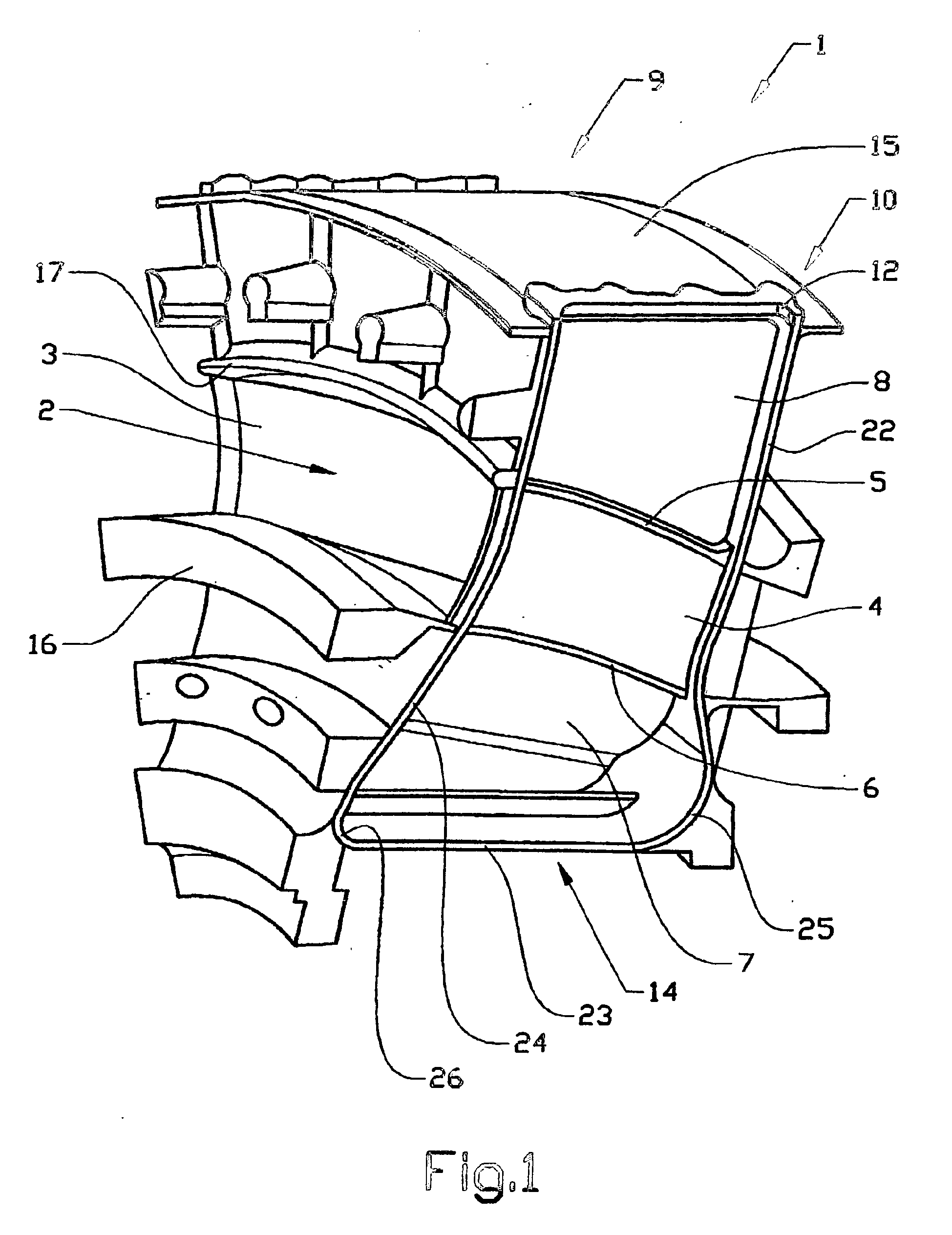
Figure 1 shows a cast sector in perspective view,
Figure 2 shows the stator component constructed of a plurality of sectors according
to Figure 1 in the direction of its circumference, and
Figure 3 shows an enlarged view of a part of the component according to Figure 2,
and more specifically the dividing area between two sectors, where the ribs of two
adjacent sectors have been joined together by the deposition of metallic material.
DETAILED DESCRIPTION OF A PREFERRED EMBODIMENT
[0015] Figure 1 shows a cast sector 1 in a perspective view. The sector 1 has a gas duct
2 that goes right through, principally in an axial direction. It is also possible
to have one or more gas ducts in a radial direction for compressor flow (not shown),
and also in certain cases fan flow.
[0016] The sector 1 has been cast with wall elements 4, 5, 6, 7, 8 that form a continuous
structure in the radial direction in order to transfer loads. In the illustrated embodiment,
the sector 1 comprises a first wall element 3 and a second wall element 4, which extend
in the intended radial direction of the stator component and are arranged at a distance
from each other in order to define between them the gas duct 2 in the direction of
the circumference of the stator component.
[0017] When two sectors are joined together, the continuous wall structure 4, 5, 6, 7, 8
together with a corresponding wall structure 21 of an adjacent sector form a device
11 extending in the radial direction of the component for guiding the said gas flow
and transferring loads in a radial/axial/tangential direction during operation of
the component, see Figure 2. This device 11 for guiding/load transference is usually
called a strut. In the illustrated embodiment, the division between two adjacent sectors
is thus made straight through such a strut. For certain applications, it can, however,
be more appropriate to make the division between the struts. According to the illustrated
embodiment, however, the stator component comprises such a complicated inner hub section
that the only reasonable division is to go through the struts.
[0018] The sector 1 comprises, in addition, a third wall element 5, that extends between
the first wall element 3 and the second wall element 4 and defines the gas duct 2
radially outwards. The sector 1 comprises, in addition, a fourth wall element 6 that
extends between the first wall element 3 and the second wall element 4 and defines
the gas duct radially inwards.
[0019] The ends 9, 10 of the sector 1 in the direction of the circumference have a design
that complements the ends of the adjacent sector, in order that, when they are placed
next to each other, they will at least essentially fit tightly against each other.
The ends 9, 10 in the direction of the circumference have, more specifically, a rectilinear
delimitation in the radial direction. As a result of this design, two adjacent sectors
can be joined together in the direction of the circumference in a relatively easy
way from the outside.
[0020] Each of the ends 9, 10 of the sector 1 comprises an elongated continuous surface
22, 23, 24, 25, 26 which delimits the sector 1 in the direction of the circumference
and which is intended to be welded. The welding surface extends at least partially
around the sector body at the periphery of the sector. The welding surface comprises
a first section 22 which extends principally in a radial direction, a second section
23 which extends principally in an axial direction, and a third section 24 which extends
principally in a radial direction. The welding is carried out in one continuous operation,
from a boss 12 at an outer end of the welding surface in a radial direction, radially
inwards, thereafter axially and finally radially outwards, back to the boss 12. The
welding surface thus forms essentially a U shape. Each of the parts 25, 26 of the
welding surface that form a change of direction between radial and axial direction
is evenly rounded off. In addition, the welding surface is essentially of the same
thickness in cross section over the whole length of the surface. The welding surface
can thus be said to constitute one continuous curve.
[0021] Other parts of the sector adjacent to the surface that is intended to be welded are
set back slightly in the direction of the circumference relative to the welding surface
in order not to interfere with the weld path. Examples of such parts are the edges
of the third and fourth wall elements 5, 6 in the direction of the circumference.
[0022] Several different welding methods are possible, but preferably laser or electron
beam welding are used.
[0023] The first and the second wall elements 3, 4 thus extend essentially in the radial
direction of the component 1. In addition, they have an extent essentially in the
axial direction of the component.
[0024] In addition, the sector 1 has a curved plate 14 for delimiting the sector radially
inwards and a curved plate 15 for delimiting the sector radially outwards.
[0025] The sector 1 is cast in such a shape that it has at least one rib 16, 17, see Figure
1, which extends in the direction of the circumference and projects in an axial direction.
The ribs 16, 17 extend different distances in the radial direction. In addition, there
is a gap in the direction of the circumference between the end 18 of the rib 17 and
the edge 19 of the sector, see Figure 3. This is in order to make the welding surface
accessible for the welding process.
[0026] After the positioning of the sectors next to each other in the direction of the circumference,
see Figure 2, the sectors are thus joined by welding the sectors' adjacent edges 19
between the ends 18, 18' of the ribs in a radial direction. Due to the design of the
sectors described above, it is possible to weld the dividing line between two adjacent
sectors. This is carried out, as mentioned above, preferably in one continuous run
per weld path.
[0027] After the said joining together, the space between two adjacent rib edges 18, 18'
is filled by deposition of metallic material 21 so that the ribs form a continuous
structure in the direction of the circumference. The continuous rib structure in the
direction of the circumference forms a reinforcing structure in the form of a circular
flange, and is used to make a joint in an axial direction to adjacent parts and/or
to bearings and seals in the gas turbine.
[0028] A plurality of identical sectors 1, 20, or sections that have different shapes but
identical cross-sections, manufactured according to the description above, are thus
arranged alongside each other, see Figure 2.
[0029] The stator component can, for example, form a load-bearing structure between bearings
arranged radially or axially internally and structures attached externally.
[0030] During the welding together, a space is created between two wall elements of two
adjacent sectors. These spaces can now be used to house various means for supplying
the component with, for example, oil and/or air, such as intakes and outlets, for
housing instruments, such as electrical and metallic cables for transmission of information
relating to measured pressure and/or temperature. The spaces can also be used for
the introduction of coolants.
[0031] The stator component can, for example, form an intake part, an intermediate housing,
a turbine exhaust housing (that is, a terminating housing part), or a part of a housing
for a gas turbine. Its main task is acting as an attachment for bearings, transferring
loads, and providing a duct for gasses.
[0032] The invention is not to be regarded as being limited to the embodiments described
above, a number of additional variants and modifications being possible within the
framework of the following claims.
1. A method for manufacturing a stator component that is intended in operation to guide
a gas flow and to transfer loads, wherein the component is constructed of at least
two sectors (1, 20) in the direction of its circumference, and wherein the sectors
are cast in separate pieces, positioned adjacent to each other and joined together
by welding, characterized in that each of the sectors (1, 20) is cast in such a shape that a first wall element (3)
and a second wall element (4) are arranged at a distance from each other in order
to define between them a gas duct (2) in the said direction of the circumference,
and in that two wall elements (4, 21) one from each of two adjacent sectors, are joined in order
to form together a device (11) extending in the radial direction of the component
for guiding the said gas flow and/or transferring loads during operation of the component.
2. A method according to Claim 1, characterized in that the surface (22, 23, 24, 25, 26) of each of the sectors (1, 20) that is intended
to be welded, extends at least partially around the sector body and is arranged at
its periphery.
3. A method according to Claim 1 or 2, characterized in that the surface (22, 23, 24, 25, 26) of each of the sectors that is intended to be welded
extends in both a radial and an axial direction.
4. A method according to Claim 3, characterized in that the part (25, 26) of the welding surface that forms a change of direction between
radial and axial direction is evenly rounded off.
5. A method according to any one of the preceding claims, characterized in that the surface (22, 23, 24, 25, 26) of each of the sectors that is intended to be welded
is continuous.
6. A method according to any one of the preceding claims, characterized in that the surface (22, 23, 24, 25, 26) of each of the sectors that is intended to be welded
is essentially the same thickness in cross section over the whole length of the surface.
7. A method according to any one of the preceding claims, characterized in that other parts (5, 6, 16, 17) of the sector adjacent to the surface (22, 23, 24, 25,
26) that is intended to be welded are set back slightly in the direction of the circumference
in relation to the welding surface in order not to interfere with the weld path.
8. A method according to any one of the preceding claims, characterized in that each of the sectors (1, 20) is cast in such a shape that it has at least one rib
(16, 17) that extends in the direction of the circumference and projects in an axial
direction.
9. A method according to Claim 8, characterized in that the said rib (16, 17) extends in such a way that there is a gap in the direction
of the circumference between the end (18) of the rib and the edge (19) of the sector.
10. A method according to Claim 9, characterized in that after the sectors (1, 20) have been placed adjacent to each other in the direction
of the circumference, the sectors are joined by welding together the sectors' adjacent
edges (19) between the ends (18, 18') of the ribs.
11. A method according to Claim 10, characterized in that after the said welding together, the space between two adjacent rib edges (18, 18')
is filled by deposition of material (21) so that the ribs form a continuous structure
in the direction of the circumference.
12. A method according to any one of the preceding claims, characterized in that two sectors (1, 20) that are intended to be joined together are cast in such shapes
that their ends (9, 10) in the direction of the circumference have designs that complement
each other, in order that, when they are placed next to each other, they will at least
essentially fit tightly against each other.
13. A method according to any one of the preceding claims, characterized in that two sectors (1, 20) that are intended to be joined together are cast in such shapes
that the end surfaces of their ends (9, 10) extend in the direction of the circumference
parallel to a plane in the radial direction.
14. A method according to any one of the preceding claims, characterized in that two adjacent sectors (1, 20) are joined together by laser welding from the outside
of the sector.
15. A method according to any one of the preceding claims, characterized in that the sector is cast with wall elements that form a continuous structure in the radial
direction in order to transfer loads.
16. A method according to any one of the preceding claims, characterized in that each of the sectors (1, 20) is cast in such a shape that the first wall element (3)
and the second wall element (4) are arranged in relation to each other in such a way
that in the intended position in the component they at least partially extend essentially
in the radial direction of the component.
17. A method according to any one of the preceding claims, characterized in that the stator component is intended for a gas turbine.
18. A method according to any one of the preceding claims, characterized in that the stator component is intended for a jet engine.
1. Verfahren zur Herstellung eines Statorbauelements, das im Betrieb zum Führen eines
Gasstroms und zum Übertragen von Lasten vorgesehen wird, wobei
- das Bauelement aus wenigstens zwei Sektoren (1, 20) in der Richtung seines Umfangs
aufgebaut wird und
- die Sektoren als getrennte Stücke gegossen, angrenzend aneinander angeordnet und
miteinander durch Schweißen verbunden werden,
dadurch gekennzeichnet,
- dass jeder der Sektoren (1, 20) zu einer solchen Form gegossen wird, dass ein erstes Wandelement
(3) und ein zweites Wandelement (4) in einem Abstand voneinander angeordnet sind,
um zwischen sich einen Gaskanal (2) in der Umfangsrichtung zu bilden, und
- dass zwei Wandelemente (4, 21), nämlich eines von jedem der beiden benachbarten Sektoren,
verbunden werden, um zusammen eine Vorrichtung (11) zu bilden, die sich in der Radialrichtung
des Bauelements zum Leiten des Gasstroms und/oder zum Übertragen von Lasten während
des Betriebs des Bauelements erstreckt.
2. Verfahren nach Anspruch 1, dadurch gekennzeichnet, dass die Oberfläche (22, 23, 24, 25, 26) eines jeden der Sektoren (1, 20), der für das
Verschweißen vorgesehen wird, sich wenigstens teilweise um den Körper des Sektors
herum erstreckt und an seinem Umfang angeordnet wird.
3. Verfahren nach Anspruch 1 oder 2, dadurch gekennzeichnet, dass die Oberfläche (22, 23, 24, 25, 26) eines jeden der Sektoren, der für das Verschweißen
vorgesehen wird, sich sowohl in Radial- als auch in Axialrichtung erstreckt.
4. Verfahren nach Anspruch 3, dadurch gekennzeichnet, dass der Teil (25, 26) der Schweißoberfläche, der eine Richtungsänderung zwischen Radial-
und Axialrichtung bildet, gleichmäßig abgerundet wird.
5. Verfahren nach einem der vorhergehenden Ansprüche, dadurch gekennzeichnet, dass die Oberfläche (22, 23, 24, 25, 26) eines jeden der Sektoren, die für das Verschweißen
vorgesehen werden, durchgehend ausgebildet werden.
6. Verfahren nach einem der vorhergehenden Ansprüche, dadurch gekennzeichnet, dass die Oberfläche (22, 23, 24, 25, 26) eines jeden der Sektoren, die für das Verschweißen
vorgesehen werden, im Querschnitt über der gesamten Länge der Oberfläche im Wesentlichen
die gleiche Dicke hat.
7. Verfahren nach einem der vorhergehenden Ansprüche, dadurch gekennzeichnet, dass die anderen Teile (5, 6, 16, 17) des Sektors angrenzend an die
Oberfläche (22, 23, 24, 25, 26), die für das Verschweißen vorgesehen wird, etwas in
Umfangsrichtung bezogen auf die Schweißoberfläche zurückgesetzt werden, um die Schweißbahn
nicht zu behindern.
8. Verfahren nach einem der vorhergehenden Ansprüche, dadurch gekennzeichnet, dass jeder der Sektoren (1, 20) in einer solchen Form gegossen wird, dass er wenigstens
eine Rippe (16, 17) hat, die sich in der Umfangsrichtung erstreckt und in Axialrichtung
vorsteht.
9. Verfahren nach Anspruch 8, dadurch gekennzeichnet, dass sich die Rippe (16, 17) so erstreckt, dass in Umfangsrichtung zwischen dem Ende (18)
der Rippe und dem Rand (19) des Sektors ein Spalt vorhanden ist.
10. Verfahren nach Anspruch 9, dadurch gekennzeichnet, dass, nachdem die Sektoren (1, 20) angrenzend aneinander in Umfangsrichtung angeordnet
worden sind, die Sektoren dadurch verbunden werden, dass die benachbarten Ränder (19) der Sektoren zwischen den Enden
(18, 18') der Rippen zusammengeschweißt werden.
11. Verfahren nach Anspruch 10, dadurch gekennzeichnet, dass nach dem Zusammenschweißen der Zwischenraum zwischen zwei benachbarten Rippenrändern
(18, 18') durch Ablage von Material (21) so gefüllt wird, dass die Rippen in der Umfangsrichtung
einen durchgehenden Aufbau bilden.
12. Verfahren nach einem der vorhergehenden Ansprüche, dadurch gekennzeichnet, dass zwei Sektoren (1, 20), die miteinander verbunden werden sollen, zu solchen Formen
gegossen werden, dass ihre Enden (9,10) in der Umfangsrichtung so gebaut sind, dass
sie einander ergänzen, damit, wenn sie nahe zueinander angeordnet werden, sie wenigstens
im Wesentlichen eng aneinander angepasst sind.
13. Verfahren nach einem der vorhergehenden Ansprüche, dadurch gekennzeichnet, dass zwei Sektoren (1, 20), die miteinander verbunden werden sollen, zu solchen Formen
gegossen werden, dass die Stirnflächen an ihren Enden (9, 10) sich in der Umfangsrichtung
parallel zu einer Ebene in der Radialrichtung erstrecken.
14. Verfahren nach einem der vorhergehenden Ansprüche, dadurch gekennzeichnet, dass zwei benachbarte Sektoren (1, 20) miteinander durch Laserverschweißung von der Außenseite
des Sektors verbunden werden.
15. Verfahren nach einem der vorhergehenden Ansprüche, dadurch gekennzeichnet, dass der Sektor mit Wandelementen gegossen wird, die für die Übertragung von Lasten in
der Radialrichtung einen fortlaufenden Aufbau bilden.
16. Verfahren nach einem der vorhergehenden Ansprüche, dadurch gekennzeichnet, dass jeder der Sektoren (1, 20) zu einer solchen Form gegossen wird, dass das erste Wandelement
(3) und das zweite Wandelement (4) bezogen aufeinander so angeordnet sind, dass sie
in der in dem Bauelement vorgesehenen Position sich wenigstens teilweise im Wesentlichen
in der Radialrichtung des Bauelements erstrecken.
17. Verfahren nach einem der vorhergehenden Ansprüche, dadurch gekennzeichnet, dass das Statorbauelement für eine Gasturbine vorgesehen wird.
18. Verfahren nach einem der vorhergehenden Ansprüche, dadurch gekennzeichnet, dass das Statorbauelement für ein Strahltriebwerk vorgesehen wird.
1. Procédé de fabrication d'un composant de stator qui est prévu, en fonctionnement,
pour guider un écoulement de gaz et pour transférer des charges, dans lequel le composant
est constitué d'au moins deux secteurs (1, 20) dans la direction de sa circonférence,
et dans lequel les secteurs sont coulés en des pièces séparées, positionnées adjacentes
les unes aux autres et reliées ensemble par soudage, caractérisé en ce que chacun des secteurs (1, 20) est coulé dans une telle forme qu'un premier élément
de paroi (3) et un second élément de paroi (4) sont agencés à une distance l'un de
l'autre afin de définir entre eux un conduit de gaz (2) dans ladite direction de la
circonférence, et en ce que deux éléments de paroi (4, 21), un de chacun des deux secteurs adjacents, sont reliés
afin de former ensemble un dispositif (11) s'étendant dans la direction radiale du
composant pour guider ledit écoulement de gaz et/ou transférer des charges pendant
le fonctionnement du composant.
2. Procédé selon la revendication 1, caractérisé en ce que la surface (22, 23, 24, 25, 26) de chacun des secteurs (1, 20) qu'il est prévu de
souder, s'étend au moins partiellement autour du corps de secteur et est agencée au
niveau de sa périphérie.
3. Procédé selon la revendication 1 ou 2, caractérisé en ce que la surface (22, 23, 24, 25, 26) de chacun des secteurs qu'il est prévu de souder
s'étend dans des directions radiale et axiale.
4. Procédé selon la revendication 3, caractérisé en ce que la partie (25, 26) de la surface de soudage qui forme un changement de direction
entre des directions radiale et axiale est également arrondie.
5. Procédé selon l'une quelconque des revendications précédentes, caractérisé en ce que la surface (22, 23, 24, 25, 26) de chacun des secteurs qu'il est prévu de souder
est continue.
6. Procédé selon l'une quelconque des revendications précédentes, caractérisé en ce que la surface (22, 23, 24, 25, 26) de chacun des secteurs qu'il est prévu de souder
a essentiellement la même épaisseur en coupe transversale sur toute la longueur de
la surface.
7. Procédé selon l'une quelconque des revendications précédentes, caractérisé en ce que d'autres parties (5, 6, 16, 17) du secteur adjacent à la surface (22, 23, 24, 25,
26) qu'il est prévu de souder sont établies en arrière légèrement dans la direction
de la circonférence par rapport à la surface de soudage, pour ne pas interférer avec
le trajet de soudage.
8. Procédé selon l'une quelconque des revendications précédentes, caractérisé en ce que chacun des secteurs (l, 20) est coulé dans une telle forme telle qu'il a au moins
une nervure (16, 17) qui s'étend dans la direction de la circonférence, et qui fait
saillie dans une direction axiale.
9. Procédé selon la revendication 8, caractérisé en ce que ladite nervure (16, 17) s'étend d'une telle manière qu'il y a un espace dans la direction
de la circonférence entre l'extrémité (18) de la nervure et le bord (19) du secteur.
10. Procédé selon la revendication 9, caractérisé en ce qu'après que les secteurs (1, 20) aient été mis en place adjacents l'un à l'autre dans
la direction de la circonférence, les secteurs sont reliés en soudant ensemble les
bords de secteurs adjacents (19) entre les extrémités (18, 18') des nervures.
11. Procédé selon la revendication 10, caractérisé en ce qu'après ledit soudage, l'espace entre deux bords de nervure adjacents (18, 18') est
rempli par le dépôt du matériau (21), de sorte que les nervures forment une structure
continue dans la direction de la circonférence.
12. Procédé selon l'une quelconque des revendications précédentes, caractérisé en ce que deux secteurs (1, 20) qui sont prévus pour être reliés ensemble sont coulés en des
formes telles que leurs extrémités (9, 10), dans la direction de la circonférence,
ont des conceptions qui se complètent mutuellement pour, quand ils sont mis en place
l'un à côté de l'autre, qu'ils s'agencent au moins sensiblement de manière serrée
l'un contre l'autre.
13. Procédé selon l'une quelconque des revendications précédentes, caractérisé en ce que deux secteurs (1, 20) qui sont prévus pour être reliés ensemble sont coulés en des
formes telles que les surfaces d'extrémité de leurs extrémités (9, 10) s'étendent
dans la direction de la circonférence parallèlement à un plan dans la direction radiale.
14. Procédé selon l'une quelconque des revendications précédentes, caractérisé en ce que deux secteurs adjacents (1, 20) sont reliés ensemble par soudage au laser à partir
de l'extérieur du secteur.
15. Procédé selon l'une quelconque des revendications précédentes, caractérisé en ce que le secteur est coulé avec des éléments de paroi qui forment une structure continue
dans la direction radiale afin de transférer des charges.
16. Procédé selon l'une quelconque des revendications précédentes, caractérisé en ce que chacun des secteurs (1, 20) est coulé dans une forme telle que le premier élément
de paroi (3) et le second élément de paroi (4) sont agencés l'un par rapport à l'autre
d'une manière telle que dans la position prévue dans le composant, ils s'étendent
au moins partiellement sensiblement dans la direction radiale du composant.
17. Procédé selon l'une quelconque des revendications précédentes, caractérisé en ce que le composant de stator est prévu pour une turbine à gaz.
18. Procédé selon l'une quelconque des revendications précédentes, caractérisé en ce que le composant de stator est prévu pour un moteur à réaction.