|
(11) | EP 1 790 264 A2 |

| (12) | EUROPEAN PATENT APPLICATION |
|
|
|
|
|||||||||||||||||||||||
| (54) | Fan assembly for vacuum cleaner |
| (57) The present invention relates to a fan assembly (7) for a vacuum cleaner (1) for
reducing BPF noises. The fan assembly includes a motor (10); an impeller (20) having
a plurality of impeller blades (23), the impeller (20) being rotated by the motor
(10) to suck air; and a diffuser (30) disposed to wrap around an outer circumference
of the impeller (20), the diffuser (30) having a plurality of diffuser blades (31)
arranged in a predetermined interval. A ratio of an exit area of the diffuser (30)
to an entrance area of the diffuser is determined to reduce noise generated when the
impeller (20) rotates.
|
REFERENCE TO RELATED APPLICATION
[0001] This application claims the benefit under 35 U.S.C. § 119(a) from Korean Patent Application No. 2005-114158 filed on November 28, 2005 in the Korean Intellectual Property Office, the disclosure of which is incorporated herein by reference in its entirety.
BACKGROUND OF THE INVENTION
Field of the Invention
[0002] The present invention relates to a vacuum cleaner. More particularly, the present invention relates to a fan assembly for a vacuum cleaner.
Description of the Related Art
[0003] Generally, a vacuum cleaner is an apparatus that sucks contaminants with air by suction force, and then, separates and collects contaminants from the sucked air using a contaminants collecting apparatus. An example of the vacuum cleaner is shown in Fig. 1.
[0004] Referring to Fig. 1, the vacuum cleaner 1 includes a suction brush 2, an extension pipe assembly 3, and a main body 4.
[0005] The suction brush 2 is provided with a suction port (not shown) at a bottom surface thereof, and sucks contaminants from a cleaning surface. The extension pipe assembly 3 connects the suction brush 2 with the main body 4 so as to form a pathway through which sucked contaminants are moved. The main body 4 has a contaminant collecting apparatus 6 and a fan assembly 7. The contaminant collecting apparatus 6 separates contaminants from sucked air and collects the separated contaminants. The contaminant collecting apparatus 6 may be implemented by any of a general dust bag or a cyclone dust collecting apparatus or so on. The fan assembly 7 generates the suction force for sucking air and contaminants.
[0006] The fan assembly 7 includes a motor 9, an impeller (not shown), and a diffuser 8. The impeller is mounted on a rotation shaft of the motor 9. The motor 9 rotates the impeller to generate suction force, sucking air and contaminants. The diffuser 8 guides air being discharged from the impeller to the motor 9 so that the air cools the motor 9 and then is discharged outside through an outlet 5 of the main body 4.
[0007] However, the fan assembly 7 generates a loud noise because the impeller rotates at high speed inside the diffuser 8. Especially, the impeller has a plurality of blades so that peak noises are generated at BPF (Blade Passing Frequency) and at integer multiply frequencies of the BPF. The peak noises are referred to as BPF noises. Here, the BPF presents the number of blades passing per second measured in cycles per second (Hz). BPF noises do not greatly affect the whole noise level of the vacuum cleaner, but they cause users to feel ill because they are high frequency noises with strong tones.
SUMMARY OF THE INVENTION
[0008] The present invention has been developed in order to overcome the above drawbacks and other problems associated with the conventional arrangement. An aspect of the present invention is to provide a fan assembly for a vacuum cleaner to reduce noise, especially BPF noises, generated by an impeller. The above aspect and/or other feature of the present invention can substantially be achieved by providing a fan assembly for a vacuum cleaner, which includes a motor; an impeller having a plurality of impeller blades, the impeller being rotated by the motor to suck air; and a diffuser disposed to wrap around an outer circumference of the impeller, the diffuser having a plurality of diffuser blades arranged in a predetermined interval. A ratio of an exit area of the diffuser to an entrance area of the diffuser is determined to reduce noise generated when the impeller rotates.
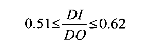
[0009] In one embodiment of the present invention, the ratio of an exit area of the diffuser to an entrance area of the diffuser satisfies a follow formula:
where DI is the entrance area of the diffuser, and DO is the exit area of the diffuser.
[0010] The diffuser is formed to satisfy the formula by controlling the number of the diffuser blades or an inclined angle of each entrance of the plurality of diffuser blades.
[0011] The fan assembly for the vacuum cleaner according to an embodiment of the present invention as described above can reduce the BPF noises while minimizing the decrease of suction force.
[0012] Furthermore, with the fan assembly for the vacuum cleaner according to an embodiment of the present invention, it is easy to control a ratio of the diffuser exit area to the diffuser entrance area by controlling the number of the diffuser blades or an inclined angle of an entrance of the diffuser blade.
[0013] Other objects, advantages and salient features of the invention will become apparent from the following detailed description, which, taken in conjunction with the annexed drawings, discloses preferred embodiments of the invention.
BRIEF DESCRIPTION OF THE DRAWINGS
[0014] These and/or other aspects and advantages of the invention will become apparent and more readily appreciated from the following description of the embodiments, taken in conjunction with the accompanying drawings of which:
[0016] Fig. 2 is a sectional view illustrating a fan assembly for a vacuum cleaner according to an embodiment of the present invention;
[0020] Fig. 6 is a partial perspective view illustrating a diffusing channel of the diffuser of Fig. 5;
[0021] Fig. 7 is a partial plain view for explaining changes of a sectional area of an entrance of a diffusing channel according to changes of an inclined angle of an entrance of a diffuser blade;
[0022] Fig. 8 is a graph illustrating a relationship between suction force of a fan assembly and ratios of a diffuser exit area to a diffuser entrance area; and
[0023] Fig. 9 is a graph illustrating a relationship between BPF noises and ratios of a diffuser exit area to a diffuser entrance area.
[0024] Throughout the drawings, like reference numerals will be understood to refer to like parts, components and structures.
DETAILED DESCRIPTION OF THE EXEMPLARY EMBODIMENTS
[0025] Hereinafter, certain exemplary embodiments of the present invention will be described in detail with reference to the accompanying drawings.
[0026] The matters defined in the description, such as a detailed construction and elements thereof, are provided to assist in a comprehensive understanding of the invention. Thus, it is apparent that the present invention may be carried out without those defined matters. Also, well-known functions or constructions are omitted to provide a clear and concise description of exemplary embodiments of the present invention.
[0027] Referring to Fig. 2, a fan assembly 40 for a vacuum cleaner according to an embodiment of the present invention includes a motor 10, an impeller 20, and a diffuser 30.
[0028] The motor 10 rotates the impeller 20, and any of various types of motors, which are generally used in vacuum cleaners, may be used as the motor 10. The motor 10, in general, has a rotation speed range of 30,000~36,000 rpm, and a capacity range of 1,000~2,000W.
[0029] Referring to Fig. 3, the impeller 20 is rotated by the motor 10 so as to generate suction force sucking air, and includes an upper plate 22, a lower plate 21, and a plurality of impeller blades 23.
[0030] The upper plate 22 is formed in a substantially disk shape, and an air inlet 25 is formed at a center of the upper plate 22. The lower plate 21 is formed a disk shape corresponding to the upper plate 22 and a center of the lower plate 21 is fixed to a motor shaft 11. The plurality of impeller blades 23 is radially arranged at a predetermined interval between the upper plate 22 and the lower plate 21. Each of the plurality of impeller blades 23 is bent with a predetermined curvature. Therefore, air entering through the air inlet 25 is discharged outside the impeller 20 through a plurality of air channels formed by the plurality of impeller blades 23.
[0031] The diffuser 30 guides air discharged from the impeller 20 to the motor 10. Referring to Figs. 4 and 5, the diffuser 30 includes a diffuser plate 32, a plurality of diffuser blades 31, and a plurality of guiding blades 33.
[0032] The diffuser plate 32 is formed in a substantially disk shape and is disposed between the impeller 20 and the motor 10. The diffuser plate 32 has on a center thereof a boring hole 34 through which the motor shaft 11 passes. The plurality of diffuser blades 31 is disposed on an upper surface of the diffuser plate 32 to wrap around the impeller 20. In other words, the diffuser blades 31 are radially disposed at a predetermined interval on an outer circumference of the diffuser plate 32. A space between neighboring diffuser blades 31 forms a diffusing channel 36. An impeller-side end 3 1b of each of the diffuser blades 31 forms an entrance of the diffusing channel 36. Each of the plurality of diffuser blades 31 is bent with a predetermined curvature as shown in Fig. 5. The plurality of guiding blades 33 is radially disposed at a predetermined interval on an under surface of the diffuser plate 32. A space between neighboring 2 guiding blades 33 forms a guiding channel 37. The plurality of guiding blades 33 is formed to guide air entered from the plurality of diffusing channels 36 to the motor 10. A plurality of openings 35 is formed at each outer end of the diffusing channels 36 on the diffuser plate 32 to fluidly communicate the diffusing channels 36 and the guiding channels 37. Each of the openings 35 covered by an upper cover 15 forms an exit of each of the diffusing channels 36. Therefore, air passing through each of the diffusing channels 36 flows to each of the guiding channels 37 through the plurality of openings 35, and then, is guided to the motor 10.
[0033] The upper cover 15 covers upper sides of both of the impeller 20 and the diffuser 30 to form a space in which the impeller 20 rotates. The upper cover 15 prevents air discharged from the impeller 20 from leaking out a top end of the diffuser 30.
[0034] The inventors have determined that noise, especially BPF noises, generated by the impeller 20 rotating inside the plurality of diffuser blades 31 may be decreased while minimizing a decrease of suction force of the fan assembly 40 if the diffuser 30 has a ratio of a diffuser exit area to a diffuser entrance area within a predetermined range. Then, the inventors have, through experimentation, determined the predetermined range of the ratio of the diffuser exit area to the diffuser entrance area that can decrease the BPF noises of the impeller 20 while minimizing the decrease of suction force of the fan assembly 40. Here, the diffuser exit area means an exit area of the diffuser 30, and the diffuser entrance area means an entrance area of the diffuser 30.
[0035] At this time, the diffuser entrance area is computed by multiplying an entrance cross sectional area of one diffusing channel 36 by the number of the diffuser blades 31. The entrance cross sectional area of one diffusing channel 36, referring Fig. 6, is computed by multiplying a height H of the diffuser blade 31 by a length B of a vertical line from an entrance end 31b of the diffuser blade 31 to next diffuser blade 31'. In other words, the entrance cross sectional area of one diffusing channel 36 is computed by Formula 1:
[0037] where, CI is the entrance cross sectional area of one diffusing channel 36, B is a length of a vertical line from an entrance end of the diffuser blade 31 to next diffuser blade 31', and H is a height of the diffuser blade 31.
[0040] where, DI is the diffuser entrance area, CI is the entrance cross sectional area of one diffusing channel 36, and N is the number of the diffuser blades 31.
[0041] Furthermore, the diffuser exit area is computed by multiplying an opening area forming an exit of the diffusing channel 36 by the number of the diffuser blades 31. Referring Fig. 5 and 7, the opening 35 of the diffusing channel 36 is formed at an outer circumference of the diffuser plate 32 forming a bottom surface of the diffusing channel 36.
[0044] where, DO is the diffuser exit area, CO is the opening area of the diffusing channel 36, and N is the number of the diffuser blades 31.
[0045] Here, the ratio of the diffuser exit area to the diffuser entrance area is defined as Formula 4:
[0047] where, R is the ratio of the diffuser exit area to the diffuser entrance area, and DI is the diffuser entrance area, and DO is the diffuser exit area.
[0048] The inventors have measured the changes of suction force and BPF noises corresponding to the changes of the ratio of the diffuser exit area to the diffuser entrance area of the fan assembly 40 for the vacuum cleaner. The results are shown in Table 1, and Figs. 8 and 9.
[0049]
Table 1
| Area of Diffuser (mm2) | R | Peak value of BPF noises (dB) | Suction force (W) | ||||
| Entrance | Exit | 1st | 2nd | 3rd | Total H | ||
| 330 | 728 | 0.45 | 64.4 | 68.7 | 55.1 | 65.5 | 549 |
| 374 | 728 | 0.51 | 65.9 | 68.1 | 55.5 | 65.5 | 620 |
| 435 | 801 | 0.54 | 66.3 | 68.2 | 59.6 | 65.9 | 643 |
| 435 | 697 | 0.62 | 70.9 | 71.2 | 59.8 | 69.5 | 646 |
| 519 | 815 | 0.64 | 74.8 | 68.1 | 63.7 | 71.1 | 657 |
| 612 | 728 | 0.84 | 72.7 | 72.5 | 66.2 | 71.3 | 662 |
[0050] In one embodiment a motor 10 of the fan assembly 40 has a capacity of 1800W, and operates approximately at 31,000 rpm, 230 V, and 50 Hz. In the impeller 20, a maximum height is 17.4mm, a minimum height is 8mm, an inner diameter, namely, a diameter of the air inlet 25 is 35mm, and an outer diameter is 109.6mm (see Fig. 3). In the diffuser 30, a height is 23.5mm, a height of the diffuser blade 31 is 10mm, and an outer diameter is 130mm (see Fig. 4).
[0051] A curve shown in Fig. 8, and four straight lines 1,2,3, and 4 shown in Fig. 9 illustrate the data of Table 1. In Fig. 9, straight lines 1,2,3, and 4 indicate a first, a second, a third, and a total BPF noise, respectively.
[0052] Referring to Fig. 8, suction force of the fan assembly 40 rises substantially in proportion to a rise in the ratio of the diffuser exit area to the diffuser entrance area (hereinafter, referred to as a diffuser area ratio), and then, when the diffuser area ratio becomes over a predetermined value, the suction force decreases. Therefore, referring to Fig. 8, a maximum suction force of the fan assembly according to this embodiment is approximately 675W. When the diffuser area ratio is 0.51, the suction force is approximately 600W. As a result, with the objective of minimizing the decrease in suction force of the fan assembly 40 (the rate of decrease is below 10%), it is preferable that the diffuser area ratio is approximately 0.51 and over.
[0053] Referring to Fig. 9, as the diffuser area ratio decreases, a first, a second, a third, and a total BPF noise 1,2,3, and 4 decrease. Also, as the diffuser area ratio increases, a first, a second, a third, and a total BPF noise 1, 2, 3, and 4 increase. As a result, with the objective of keeping a first, a second, a third, and a total BPF noise 1, 2, 3, and 4 of the fan assembly 40 approximately 70 dB and below, it is preferable that the diffuser area ratio is approximately 0.62 and below.
[0054] As a result described above, with the objective of minimizing the decrease of suction force and keeping a first, a second, a third, and a total BPF noise 1, 2, 3, and 4 of the fan assembly 70 dB and below, it is preferable that the diffuser 30 is formed to have a range of the diffuser area ratio of 0.51 ~ 0.62.
[0055] Any one or both of the diffuser exit area and the diffuser entrance area as described above may be controlled so that the diffuser 30 has the substantially same size as the conventional diffuser and the diffuser area ratio may come within the range described above.
[0056] For an example, the diffuser exit area may be constant and the diffuser entrance area is controlled so that the ratio of the diffuser exit area to the diffuser entrance area is controlled. For this purpose, below methods can be used.
[0057] First, controlling of the number of the diffuser blades 31 causes the diffuser entrance area to be controlled. At this time, when the number of the diffuser blades 31 increases, a gap between neighboring 2 diffuser blades 31 narrows thereby the diffuser area ratio decreasing. As a result, the diffuser entrance area with respect to the diffuser exit area decreases so that the diffuser area ratio decreases. Contrarily, when the number of the diffuser blades 31 decreases, a gap between neighboring 2 diffuser blades 31 widens thereby the diffuser area ratio increasing.
[0058] Second, controlling of an inclined angle θ of the entrance of the diffuser blade 31 causes the diffuser entrance area to be controlled. Here, the inclined angle θ of the entrance of the diffuser blade 31 means an angle that an entrance end of the diffuser blade 31 is inclined. Accordingly, the maximum inclined angle of the entrance of the diffuser blade 31 is 90°. When the inclined angle θ of the entrance of the diffuser blade 31 is 90°, the diffuser entrance area is minimum. As the inclined angle θ of the entrance of the diffuser blade 31 decreases, the diffuser entrance area increases. These are because the diffuser entrance area is defined as an area of a section 38 of the diffusing channel 36 at a point P where a top end 31a of the diffuser blade 31 meets the inclined entrance end 3 1 b of the diffuser blade 31 (see Fig. 6).
[0059] Because the diffusing channel 36 is formed to diffuse from the entrance to the exit, a gap between neighboring 2 diffuser blades 31 and 31' becomes gradually wider from the entrance to the exit. Fig. 7 is a plain view for explaining changes of gap dimension between neighboring 2 diffuser blades 31 and 31' corresponding to changes of the inclined angle θ of the entrance of the diffuser blade 31. P is a first point where the top end 31a of the diffuser blade 31 meets the inclined entrance end 31b of the diffuser blade 31 when the inclined angle of the entrance of the diffuser blade is θ as shown in Fig. 6, B is the gap dimension between the 2 diffuser blades 31 and 31' of this case. P 1 is a second point where the top end 31a of the diffuser blade 31 meets the inclined entrance end 31b of the diffuser blade 31 when the inclined angle of the entrance of the diffuser blade 31 is more than θ, B 1 is the gap dimension between the 2 diffuser blades 31 and 31' of this case. P2 is a third point where the top end 31a of the diffuser blade 31 meets the inclined entrance end 31b of the diffuser blade 31 when the inclined angle of the entrance of the diffuser blade 31 is less than θ, B2 is the gap dimension between the 2 diffuser blades 31 and 31' of this case. At this time, because a gap between neighboring 2 diffuser blades 31 and 31' becomes gradually wider from the entrance of the diffusing channel 36 to the exit thereof, B satisfies B1< B < B2. Accordingly, as the inclined angle θ of the entrance of the diffuser blade 31 decreases, the diffuser entrance area increases gradually. As a result, controlling of the inclined angle θ of the entrance of the diffuser blade 31 can cause the ratio of the diffuser exit area to the diffuser entrance area to be controlled.
[0060] Hereinafter, operation of the fan assembly 40 for the vacuum cleaner with above-described structure will be explained in detail with reference to Figs. 2 to 4.
[0061] Upon rotating the motor 10, the impeller 20 fixed on the motor shaft 11 is rotated. As the impeller 20 rotates, air is sucked in through the air inlet 25, and then, is discharged to the diffuser 30 through the exit of the impeller 20. The air discharged from the impeller 20 is entered into each entrance of the plurality of diffusing channels 36, and then, passes through each of the diffusing channels 36 thereby being discharged to each of the guiding channels 37 through the opening 35 that is an exit of the diffusing channel 36. At this time, the ratio of the diffuser exit area to the diffuser entrance area is a range of 0.51~0.62 so that the BPF noises generated by impeller rotation are minimized. The air entered into the guiding channels 37 passes through the motor 10, and then, is discharged outside the main body through an air outlet.
[0062] While the embodiments of the present invention have been described, additional variations and modifications of the embodiments may occur to those skilled in the art once they learn of the basic inventive concepts. Therefore, it is intended that the appended claims shall be construed to include both the above embodiments and all such variations and modifications that fall within the spirit and scope of the invention.
1. A fan assembly for a vacuum cleaner comprising:
a motor;
an impeller having a plurality of impeller blades, the impeller being rotated by the motor to suck air; and
a diffuser disposed to wrap around an outer circumference of the impeller, the diffuser having a plurality of diffuser blades arranged at a predetermined interval;
wherein a ratio of an exit area of the diffuser to an entrance area of the diffuser is set to reduce noise generated when the impeller rotates.2. The fan assembly for the vacuum cleaner of claim 1, wherein the ratio of the exit
area of the diffuser to the entrance area of the diffuser satisfies a formula:
where DI is the entrance area of the diffuser, and DO is the exit area of the diffuser.
where DI is the entrance area of the diffuser, and DO is the exit area of the diffuser.
3. The fan assembly for the vacuum cleaner of claim 2, wherein the diffuser is formed
to satisfy the formula by controlling a number of the diffuser blades.
4. The fan assembly for the vacuum cleaner of claim 2, wherein the diffuser is formed
to satisfy the formula by controlling an inclined angle of each entrance of the plurality
of diffuser blades.
5. The fan assembly for the vacuum cleaner of any of claims 1 to 4, wherein the ratio
is also set to minimize a decrease in a suction force produced by the fan assembly.
6. The fan assembly for the vacuum cleaner of any of claims 1 to 5, wherein the ratio
is approximately 0.51 and greater.
REFERENCES CITED IN THE DESCRIPTION
This list of references cited by the applicant is for the reader's convenience only. It does not form part of the European patent document. Even though great care has been taken in compiling the references, errors or omissions cannot be excluded and the EPO disclaims all liability in this regard.
Patent documents cited in the description