|
(11) | EP 1 625 303 B1 |

| (12) | EUROPEAN PATENT SPECIFICATION |
|
|
| (54) |
METHOD FOR CONTROLLING A PUMP MEANS VERFAHREN ZUR STEUERUNG EINES PUMPENMITTELS PROCEDE POUR COMMANDER UNE POMPE |
|
|
|||||||||||||||||||||||||||||||
| Note: Within nine months from the publication of the mention of the grant of the European patent, any person may give notice to the European Patent Office of opposition to the European patent granted. Notice of opposition shall be filed in a written reasoned statement. It shall not be deemed to have been filed until the opposition fee has been paid. (Art. 99(1) European Patent Convention). |
[0001] The invention relates to a method for controlling a diaphragm or piston pump that is actuated via a ram or a connecting rod by a cam which is powered by an electric motor.
[0002] Diaphragm and piston pumps are used to supply metered quantities of liquids with various properties. Depending on the field of application, the pump behaviour is subject to various requirements in order to ensure that the delivered quantity of metered medium is as precise as possible and remains constant for as long as possible.
[0003] The pumps are driven by an electric motor via a cam, in such manner that the rotational motion of the motor is converted to linear motion of the pump diaphragm or pump piston. For each rotation of the cam, a compression stroke takes place, with delivery of the metered medium for example into a metered line, and an aspiration stroke, in which the metered medium is aspirated from a reservoir or similar.
[0004] Electric motors used in the prior art for driving such mechanisms include a wide range of types, particularly mechanically commuted motors, synchronous and asynchronous motors and stepping motors. However, most such drive units are associated with a number of disadvantages with regard to their respective use.
[0006] Mechanically commuted motors are prone to a high rate of mechanical wear and are therefore unsuitable for pumps with very long lifetimes.
[0007] The torque gradient of synchronous motors is disadvantageous in that it causes the frictional connection to be broken if placed under excessive load. The startup behaviour is also not ideal for the present purpose. Asynchronous motors have a rotating speed curve that is dependent on its load, which is detrimental for precise metering of quantities. The rotating speed of both synchronous and asynchronous motors is dependent on the frequency of the applied voltage, which means that electronic frequency converters are needed to control the rotating speed.
[0008] Particular problems arise when the pump is to be operated at less than its maximum metering output, which is unavoidable in many applications for precisely metered delivery. A variety of methods have been implemented to combat this in the prior art. Thus the delivered quantity of metered medium may be reduced by limiting the excursion of the pump diaphragm or piston. In this case, the cam runs freely for a part of its revolution and only moves the diaphragm or piston in a more or less extended area about front dead centre. The particular drawback of this method is that the piston or diaphragm is accelerated very rapidly for short periods depending on the delivery power, which leads to high pressure variations in the metered lines and negatively affects the metering behaviour. In the same way, the aspiration behaviour is impaired during the aspiration stroke, which degrades the aspiration behaviour of the pump if there is any air trapped in the suction line or in the case of small pump heads.
[0009] A further variant for reducing the delivery volume is pulse-pause control. In this, a metering cycle is completed and is then followed by a metering pause, which is dependent on the desired delivery quantity, and is calculated so that .the desired delivery quantity is adjusted in the temporal average. The disadvantage of this arrangement is that the pauses occurring for low delivery quantities are very long, which can cause unacceptable mixing of the metering medium in the pipeline or the tank, and is moreover associated with highly inconsistent delivery behaviour.
[0010] A further option for reducing the metered quantity is to control the rotating speed of the drive motor. In this case, the delivery quantity may be adjusted by influencing the speed of the piston or diaphragm. A corresponding slowing of the drive unit and thus of the diaphragm causes a reduction in the quantity of metered medium delivered per unit of time. The problem with this approach is that under certain circumstances for a desired lengthening of the compression stroke the aspiration stroke is also lengthened at the same time. The suction and delivery behaviour is degraded thereby, particularly when dealing with highly viscous media.
[0011] In order to avoid this problem, the applicant's DE 198 23 156 A1 describes a method for operating a metering pump with an asynchronous motor. In this case, the rotating speed of the asynchronous motor is reduced during the compression stroke according to the desired metered output. During the aspiration stroke, on the other hand, the rotating speed is increased to achieve the shortest possible aspiration stroke, and thereby also shortening the pauses between compression strokes. The disadvantage of this method is that the use of an asynchronous motor necessitates a highly sophisticated system configuration, which requires a frequency converter to control the rotating speed of the asynchronous motor and sensor equipment to monitor and control the rotating speed of the motor in order to be able to compensate for the deviation caused by the load-dependent rotating speed curve.
[0012] Accordingly, the task of the present invention is to provide a method for controlling a diaphragm or piston pump that is actuated via a ram or a connecting rod by a cam which is powered by an electric motor, which allows the most precise and constant delivery possible of metered media, combined with a simple construction.
[0013] This task is solved with a method according to the type described in the introduction in which the diaphragm or piston of the pump is moved by the drive unit of the cam at approximately constant speed throughout the compression stroke, taking into account the position of the cam, to assure an approximately constant volume flow of the metered medium.
[0014] The diaphragm or piston mechanism, driven by a circular cam which is rotating at constant speed, now describes a sinusoidal speed profile. Starting from the rear dead centre, the diaphragm is accelerated, reaches the fastest speed of the compression stroke after a quarter revolution, and then slows down again until front dead centre of the cam, at which point it then transitions to the aspiration stroke, which also includes a period in which the diaphragm speeds up to its maximum speed halfway through the aspiration stroke, and is then slowed until the cam reaches rear dead centre.
[0015] In the method according to the invention, the speed of the cam is now controlled during the compression stroke in such manner that the speed profile produced is as linear and constant as possible, instead of the non-linear, sinusoidal profile created without the control. To produce this, the cam must be accelerated sharply at the start of the compression stroke and must be slowed to a minimum value by the middle of the compression stroke, at which point it is accelerated again to reach maximum speed again close to the front dead centre. This form of control of the cam speed results in a speed profile of the diaphragm or piston that is highly linear and essentially at a constant level.
[0016] This approximately constant diaphragm speed during the compression stroke causes the metered medium to be delivered at a uniform rate, which leads to highly advantageous and precise metering behaviour, even for very viscous media. A good delivery result may also be achieved by this means for very small metering outputs.
[0017] Refinements of the invention are described in the subordinate claims. Accordingly, one refinement of the invention is characterised in that the drive unit drives the cam during the compression stroke with a rotating speed profile that compensates for temporal cosinusoidal movement of the piston or diaphragm conditioned by the cam.
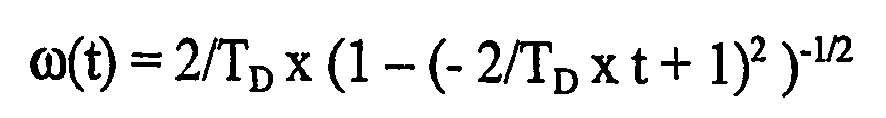
[0018] Moreover, it may also be provided that the speed profile of the drive unit has approximately the shape
in the compression stroke throughout the period of constant diaphragm speed.
[0019] The physically correct formula indicated above for compensating the cosinusoidal piston or diaphragm movement is derived by transformation of the linear movement via an arccos function and subsequent differentiation. A similar equation is derived for drive units with additional transverse movement (connecting rods).
[0020] For practical cosine compensation, the above formula may be approximated with a simplified or similar formula depending on an acceptable non-linearity of the metered quantity.
[0021] The angular velocity of the cam shown results in a constant speed of the diaphragm, except at the start and end of the compression stroke. TD represents the length of the compression stroke, the maximum diaphragm excursion being standardised to 1.
[0022] It is also possible that the drive unit moves the cam with a different speed profile, particularly with constant and/or higher speed, during the aspiration stroke.
[0023] It is desirable to keep the aspiration stroke as short as possible. In this case, depending on the metered medium it is not absolutely essential to achieve constant pressure distribution during the aspiration stroke. As a result, at the end of the compression stroke, when the rotating speed of the cam is at its greatest, as previously described, delivery can be continued at this speed, which leads to a short aspiration stroke with sinusoidal diaphragm speed. The next compression stroke can then be begun at this increased speed, which ultimately provides good system response and is less harsh on the mechanical parts of the pump.
[0024] On the other hand, maintaining the pressure distribution as constant as possible during the aspiration stroke as well may be desirable, particularly for more viscous metered media, so that a rotating speed profile similar to that of the compression stroke is selected rather than constant rotation, when it may be necessary to set a higher diaphragm speed and thus a shorter period for the aspiration stroke.
[0025] It is advantageous if the delivered volume flow of metered medium is increased shortly before the end of the compression stroke in order to compensate for the metering gap during the aspiration stroke.
[0026] It is further advantageously provided that an EC motor with integral rotor position sensors is used as the drive unit.
[0027] EC motors (electronically commuted motors) offer several advantages. Because of the brushless electronic commutation, they have a very long operating life and low wear characteristics, which is important for metering pumps that may have operating lives longer than 10,000 hours. In addition, most are equipped with integral sensors for the rotor position, the signals from which may also be used to control the cam position according to the suggested method, thereby reducing total costs. Due to the high dynamic ratio of EC motors, it is also very easy to achieve the rapid changes in speed that are necessary for the suggested method.
[0028] One refinement of the method is notable in that in order to control the cam speed, the cam position is captured by a sensor and/or is calculated from position sensor signals that are in the drive unit.
[0029] Besides control of the cam position and thus also of the diaphragm excursion, under certain circumstances it may be helpful in the suggested method to provide a position controller to improve the metering behaviour of the pump, particularly since the necessary rotating speed of the cam is determined by its current position. In this way, by measuring and monitoring the cam position, it is possible to achieve the most constant diaphragm speed possible, as is desired. In such case, the position of the cam may either be measured directly, or position signals may be used, as provided by the sensors located in the drive unit, or to capture the linear movement of the ram pr connecting rod.
[0030] In the following, the invention will be explained in greater detail with reference to the drawing. In the drawing:
- Fig. 1
- is a schematic representation of a diaphragm pump driven by the method according to the invention,
- Fig. 2
- is a diagram of the diaphragm or piston excursion that is achieved with the method according to the invention, also showing the volume flow of the metered medium, and
- Fig. 3
- is a diagram of the angle of rotation and the change of angle of rotation for the cam.
[0031] With a diaphragm pump 1 operated according to the method according to the invention, a medium to be metered is delivered from a reservoir - not shown in detail - that is connected via a hose to an aspiration orifice 2 of diaphragm pump 1, through a delivery orifice 3 and to a metering hose - also not further shown - connected thereto. The pump operation is effected by diaphragm 4, which is displaced linearly by a ram 5.
[0032] Ram 5 is moved by a circular cam 6, such that the rotating motion of a drive shaft 7, which is non-positively connected to cam 6, is converted by ram 5 to a backward and forward motion of diaphragm 4.
[0033] Shaft 7 is driven by an electronically commuting motor 9 via a transmission 8. A motor controller 10 is connected to motor 9 via motor connector terminals 10a, and includes the power electronic components required for operation as well as a position control circuit. Motor 9 is equipped with rotor position sensors 11, which transmit the current position of the rotor to motor controller 10 via control circuits 11 a, on the basis of which information the controller controls the flow of current to motor 9. Then, depending on the rotor position returned by sensors 11, current is applied to the corresponding phases of motor 9 such that a rotating field is created inside the motor, which field continuously sets the rotor in motion. Because of this electronically created rotating field, it is no longer necessary to provide for commutation of the motor's phases by mechanical means. This form of control enables motor 9 to be driven at the desired rotating speed without dependence on load or turning moment oscillations.
[0034] Motor controller 10 is supplied with energy from a mains supply circuit 12 via energy lines 12a. Mains supply circuit 12 is connected to a conventional electric supply network 13 via energy supply lines 13a.
[0035] The position of cam 6 is captured by a position sensor 14, whose position signal is transmitted via signal circuits 14a to a positional controller 15.
[0036] Positional controller 15 is also supplied with energy from a mains supply circuit 12 via energy lines 12b. Control signals with the required quantity of metered medium are passed to positional controller 15 via a data circuit 16. Positional controller 15 calculates the currently required rotating speed for motor 9 using the position of cam 6, as measured by sensor 14, and the quantity of metered medium to be measured, as transmitted by circuit 16, and transmits this to motor controller 10 via control line 15a. Depending on the position of the rotor in motor 9, as measured by rotor position sensors 11, the motor controller 10 then adjusts the rotating field via motor connectors 10a such that motor 9 reaches the required rotating speed. Thus cam 6 is moved via transmission 8 and shaft 7 in correspondence with the set quantity of metered medium. This creates a closed control circuit that may be used to precisely control the speed of diaphragm 4, as well as its excursion caused by cam 6 via ram 5.
[0037] The profile of the diaphragm excursion effected by positional controller 15 in conjunction with motor controller 10 via drive unit, transmission and cam, and the volume flow of metered medium resulting therefrom is shown in greater detail in figure 2.
[0038] Curve 17 represents the plot of the diaphragm excursion over the course of a metering cycle. The duration of a complete metering cycle is standardised in this case to length 2. The diaphragm excursion may thus vary in this context from -1 for rear dead centre of cam 6 through the neutral position for half and three-quarters of a revolution of cam 6 and to +1 for front dead centre of the cam.
[0039] The diaphragm excursion of a metering cycle that is controlled according to the invention begins at rear dead centre 18. Cam 6 starts with a maximum rotating speed, at which the diaphragm follows the start of a cosinusoidal movement, as shown by partial curve 19. This corresponds to the plot of the diaphragm excursion, if cam 6 were to rotate at a constant, maximum speed. Immediately after this short startup phase, however, the rotating speed of the cam 6 is slowed, precisely so that diaphragm excursion 17 has an approximately linear plot, meaning that the diaphragm is being moved at constant speed. Cam 6 reaches its minimum rotating speed after half a compression stroke at a time of 0.75. Subsequently, it is accelerated again until it reaches front dead centre 20, at which point cam 6 is again rotating at maximum speed, such that the plot for the diaphragm excursion approximates the curve 21 that would be returned if cam 6 were to be driven at a constant, maximum speed.
[0040] When front dead centre 20 has been passed, the aspiration stroke begins, in which diaphragm 4 is retracted and draws fresh metered medium out of suction line 2 and into the pump chamber. In order to keep the aspiration stroke as short as possible, this is performed with the cam at maximum rotating speed to that the plot of the diaphragm excursion matches the second half of cosine oscillation 21 until rear dead centre 18 is reached for the maximum negative excursion of the diaphragm at -1. At this dead centre, the diaphragm is either stopped or a further metering cycle is begun with a compression stroke similar to the one described previously.
[0041] The plot of the volume flow of metered medium is represented by curve 22. At the start of the compression stroke the volume flow rises rapidly to its setpoint value in restriking phase 23. In the period with constant diaphragm speed, a constant volume flow is delivered to metering line 2 from connection 3. At the end of compression stroke 24, the volume flow at connection 3 falls to zero relatively quickly, and the aspiration stroke begins. The volume flow of the aspirated medium at connection 2 describes a sinusoidal curve here, due to the cosinusoidal curve of the diaphragm excursion.
[0042] The length of the compression stroke relative to the aspiration stroke is important for the metering behaviour of the pump. In general, it is desirable to keep the aspiration stroke as short as possible and the compression stroke as long as possible. The size of the volume flow and thus also the quantity of metered medium delivered per unit of time depend on the rotating speed of cam 6.
[0043] The plot of a cam rotation during a compression stroke controlled according to the invention is shown in greater detail in figure 3. In the diagram, the length of a compression stroke is standardised to 1, the plot of the rotating speed being applied as the speed in curve 25, and the plot of the cam angle being applied in curve 26.
[0044] At the start of the compression stroke, the cam starts at maximum speed and is then slowed until it reaches its minimum rotating speed halfway through the compression stroke, only to be accelerated over the course of the second half of the compression stroke, to reach maximum speed again by the end thereof. This is also shown in the plot of the angle of rotation in curve 26.
[0045] The invention is not limited to the example described in the aforegoing. It may be varied in many respects without exceeding the limits of the fundamental concept. Thus for example a controller similar to the one used for the compression stroke may also be used for the aspiration stroke, so that a constant delivered quantity of the metered medium may be obtained here too: this may be particularly beneficial in the case of very viscous media. A further variant consists in briefly increasing the cam speed, and thus also the quantity of metered media delivered per unit of time, just before the end of the compression stroke in order to balance the metering gap. It may also prove helpful to dispense with the sensor for measuring the cam position and instead to calculate the position of the cam from the measured rotor position. Then, only the zero position of the cam needs to be captured.
1. A method for controlling a diaphragm or piston pump that is actuated via a ram or
a connecting rod by a cam which is powered by an electric motor,
characterised in that
the diaphragm or piston of the pump is moved by the drive unit of the cam at approximately constant speed throughout the compression stroke, taking into account the position of the cam, to assure an approximately constant volume flow of the metered medium.
characterised in that
the diaphragm or piston of the pump is moved by the drive unit of the cam at approximately constant speed throughout the compression stroke, taking into account the position of the cam, to assure an approximately constant volume flow of the metered medium.
2. The method according to claim 1,
characterised in that
the drive unit drives the cam during the compression stroke with a rotating speed profile that compensates for temporal cosinusoidal movement of the piston or diaphragm conditioned by the cam.
characterised in that
the drive unit drives the cam during the compression stroke with a rotating speed profile that compensates for temporal cosinusoidal movement of the piston or diaphragm conditioned by the cam.
3. The method according to claim 1 or 2,
characterised in that
the speed profile of the drive unit has approximately the shape
in the compression stroke throughout the period of constant diaphragm speed.
characterised in that
the speed profile of the drive unit has approximately the shape
in the compression stroke throughout the period of constant diaphragm speed.
4. The method according to any of the preceding claims,
characterised in that
the drive unit moves the cam with a different speed profile, particularly with constant and/or higher speed, during the aspiration stroke.
characterised in that
the drive unit moves the cam with a different speed profile, particularly with constant and/or higher speed, during the aspiration stroke.
5. The method according to any of the preceding claims,
characterised in that
the delivered volume flow of metered medium is increased shortly before the end of the compression stroke in order to compensate for the metering gap during the aspiration stroke.
characterised in that
the delivered volume flow of metered medium is increased shortly before the end of the compression stroke in order to compensate for the metering gap during the aspiration stroke.
6. The method according to any of the preceding claims,
characterised in that
an EC motor, preferably with integral rotor position sensors, is used as the drive unit.
characterised in that
an EC motor, preferably with integral rotor position sensors, is used as the drive unit.
7. The method according to any of the preceding claims,
characterised in that
in order to control the cam speed, the cam position is captured by a sensor and/or is calculated from position sensor signals that are in the drive unit.
characterised in that
in order to control the cam speed, the cam position is captured by a sensor and/or is calculated from position sensor signals that are in the drive unit.
1. Verfahren zum Steuern einer Membran- oder Kolbenpumpe, die über einen Stößel oder
eine Verbindungsstange durch einen Nocken betätigt wird, der durch einen Elektromotor
angetrieben wird,
dadurch gekennzeichnet, dass
die Membran oder der Kolben der Pumpe durch die Antriebseinheit des Nockens mit ungefähr konstanter Geschwindigkeit während des gesamten Verdichtungshubes bewegt wird, wobei die Position des Nockens berücksichtigt wird, um einen ungefähr konstanten Volumenfluss des dosierten Mediums zu gewährleisten.
2. Verfahren nach Anspruch 1,
dadurch gekennzeichnet, dass
die Antriebseinheit den Nocken während des Verdichtungshubes mit einem Drehzahlprofil antreibt, das eine zeitliche Kosinusbewegung des Kolbens oder der Membran, die durch den Nocken bedingt wird, kompensiert.
dadurch gekennzeichnet, dass
die Antriebseinheit den Nocken während des Verdichtungshubes mit einem Drehzahlprofil antreibt, das eine zeitliche Kosinusbewegung des Kolbens oder der Membran, die durch den Nocken bedingt wird, kompensiert.
3. Verfahren nach Anspruch 1 oder 2,
dadurch gekennzeichnet, dass
das Geschwindigkeitsprofil der Antriebseinheit ungefähr die Form

in dem Verdichtungshub während des gesamten Zeitraums einer konstanten Membrangeschwindigkeit aufweist.
dadurch gekennzeichnet, dass
das Geschwindigkeitsprofil der Antriebseinheit ungefähr die Form
in dem Verdichtungshub während des gesamten Zeitraums einer konstanten Membrangeschwindigkeit aufweist.
4. Verfahren nach einem der vorangehenden Ansprüche,
dadurch gekennzeichnet, dass
die Antriebseinheit den Nocken mit einem anderen Geschwindigkeitsprofil, insbesondere mit konstanter und/oder höherer Geschwindigkeit, während des Ansaughubes antreibt.
dadurch gekennzeichnet, dass
die Antriebseinheit den Nocken mit einem anderen Geschwindigkeitsprofil, insbesondere mit konstanter und/oder höherer Geschwindigkeit, während des Ansaughubes antreibt.
5. Verfahren nach einem der vorangehenden Ansprüche,
dadurch gekennzeichnet, dass
der abgegebene Volumenfluss des dosierten Mediums kurz vor dem Ende des Verdichtungshubes erhöht wird, um das Dosierungsloch während des Ansaughubes zu kompensieren.
dadurch gekennzeichnet, dass
der abgegebene Volumenfluss des dosierten Mediums kurz vor dem Ende des Verdichtungshubes erhöht wird, um das Dosierungsloch während des Ansaughubes zu kompensieren.
6. Verfahren nach einem der vorangehenden Ansprüche,
dadurch gekennzeichnet, dass
ein EC-Motor, vorzugsweise mit integralen Rotorpositionssensoren, als die Antriebseinheit verwendet wird.
dadurch gekennzeichnet, dass
ein EC-Motor, vorzugsweise mit integralen Rotorpositionssensoren, als die Antriebseinheit verwendet wird.
7. Verfahren nach einem der vorangehenden Ansprüche,
dadurch gekennzeichnet, dass
zum Steuern der Nockengeschwindigkeit die Nockenposition durch einen Sensor erfasst wird und/oder anhand von Positionssensorsignalen, die in der Antriebseinheit sind, errechnet wird.
dadurch gekennzeichnet, dass
zum Steuern der Nockengeschwindigkeit die Nockenposition durch einen Sensor erfasst wird und/oder anhand von Positionssensorsignalen, die in der Antriebseinheit sind, errechnet wird.
1. Procédé pour commander une pompe à membrane ou à piston qui est actionnée par une
came, par l'intermédiaire d'un vérin ou d'une bielle, came qui est mue par un moteur
électrique,
caractérisé en ce que
la membrane ou le piston de cette pompe sont déplacés par le mécanisme d'entraînement de la came à une vitesse à peu près constante pendant toute la course de compression, en tenant compte de la position de la came, de façon à assurer un débit-volume à peu près constant du milieu mesuré.
2. Procédé selon la revendication 1,
caractérisé en ce que
le mécanisme d'entraînement entraîne la came pendant la course de compression avec un profil de vitesse de rotation qui compense le mouvement cosinusoïdal temporel du piston ou de la membrane conditionné par la came.
caractérisé en ce que
le mécanisme d'entraînement entraîne la came pendant la course de compression avec un profil de vitesse de rotation qui compense le mouvement cosinusoïdal temporel du piston ou de la membrane conditionné par la came.
3. Procédé selon la revendication 1 ou 2,
caractérisé en ce que
le profil de vitesse du mécanisme d'entraînement a approximativement la forme suivante

dans la course de compression pendant toute la période de vitesse constante de la membrane.
caractérisé en ce que
le profil de vitesse du mécanisme d'entraînement a approximativement la forme suivante
dans la course de compression pendant toute la période de vitesse constante de la membrane.
4. Procédé selon l'une quelconque des revendications précédentes,
caractérisé en ce que
le mécanisme d'entrainement déplace la came avec un profil de vitesse différent, particulièrement avec une vitesse constante et/ou plus élevée, pendant la course d'aspiration.
caractérisé en ce que
le mécanisme d'entrainement déplace la came avec un profil de vitesse différent, particulièrement avec une vitesse constante et/ou plus élevée, pendant la course d'aspiration.
5. Procédé selon l'une quelconque des revendications précédentes,
caractérisé en ce que
le débit-volume refoulé du milieu mesuré est augmenté peu avant la fin de la course de compression afin de compenser l'intervalle de mesure pendant la course d'aspiration.
caractérisé en ce que
le débit-volume refoulé du milieu mesuré est augmenté peu avant la fin de la course de compression afin de compenser l'intervalle de mesure pendant la course d'aspiration.
6. Procédé selon l'une quelconque des revendications précédentes,
caractérisé en ce que
un moteur commuté électroniquement, de préférence avec des capteurs de position de rotor incorporés, est utilisé comme le mécanisme d'entraînement.
caractérisé en ce que
un moteur commuté électroniquement, de préférence avec des capteurs de position de rotor incorporés, est utilisé comme le mécanisme d'entraînement.
7. Procédé selon l'une quelconque des revendications précédentes,
caractérisé en ce que
afin de contrôler la vitesse de la came, la position de la came est capturée par un capteur et/ou est calculée d'après les signaux des capteurs de position qui sont dans le mécanisme d'entraînement.
caractérisé en ce que
afin de contrôler la vitesse de la came, la position de la came est capturée par un capteur et/ou est calculée d'après les signaux des capteurs de position qui sont dans le mécanisme d'entraînement.
REFERENCES CITED IN THE DESCRIPTION
This list of references cited by the applicant is for the reader's convenience only. It does not form part of the European patent document. Even though great care has been taken in compiling the references, errors or omissions cannot be excluded and the EPO disclaims all liability in this regard.
Patent documents cited in the description