| (19) |
 |
|
(11) |
EP 0 983 894 B1 |
| (12) |
EUROPEAN PATENT SPECIFICATION |
| (45) |
Mention of the grant of the patent: |
|
11.07.2007 Bulletin 2007/28 |
| (22) |
Date of filing: 01.09.1999 |
|
| (51) |
International Patent Classification (IPC):
|
|
| (54) |
Vehicle speed control using engine and brake systems to achieve target acceleration
Geschwindigkeitsregelung für Fahrzeug mit Brems- und Motorsteuerung zur Erzeugung
einer Sollbeschleunigung
Régulation de la vitesse d'un véhicule en utilisant les freins et le moteur pour obtenir
l' accélération désirée
|
| (84) |
Designated Contracting States: |
|
DE FR |
| (30) |
Priority: |
02.09.1998 GB 9818960
|
| (43) |
Date of publication of application: |
|
08.03.2000 Bulletin 2000/10 |
| (73) |
Proprietor: Land Rover |
|
Gaydon,
Warwick CV35 0RR (GB) |
|
| (72) |
Inventor: |
|
- Beever, Paul Adrian
Solihull,
West Midlands B92 0QB (GB)
|
| (74) |
Representative: Farrow, Robert Michael et al |
|
Land Rover,
Patent Department 53G 16/4,
Banbury Road,
Lighthorne
Warwick CV35 0RG
Warwick CV35 0RG (GB) |
| (56) |
References cited: :
EP-A- 0 874 149
WO-A-96/40534
DE-A- 2 829 894
US-A- 5 125 485
US-A- 5 785 138
|
EP-A- 0 992 412
WO-A-98/34809
DE-A- 19 654 769
US-A- 5 731 977
|
|
| |
|
|
|
|
| |
|
| Note: Within nine months from the publication of the mention of the grant of the European
patent, any person may give notice to the European Patent Office of opposition to
the European patent
granted. Notice of opposition shall be filed in a written reasoned statement. It shall
not be deemed to
have been filed until the opposition fee has been paid. (Art. 99(1) European Patent
Convention).
|
[0001] The invention relates to the control of vehicle speed and in particular to improvements
in the integration of the control of vehicle speed using various components of the
vehicle.
[0002] Conventionally vehicles have an engine management system for controlling the torque
output from the engine. This may form part of an integral power train controller,
for example in hybrid vehicles where an engine and an electric motor need to be co-ordinated
to provide driving torque for the vehicle. It is also well known to control electronically
the level of braking in a vehicle using hydraulic brake modulators or control of electric
brakes. A vehicle speed control as described in the preamble of claim 1 is known from
DE 19 654 769.
[0003] The present invention aims to improve integration of the control of the various parts
of the power train and braking systems of a vehicle.
[0004] According to the present invention there is provided a vehicle speed control system
as defined in claim 1.
[0005] The use of a single speed control unit to receive signals from the driver demanding
acceleration and deceleration and control both acceleration and deceleration of the
vehicle allows a large degree of flexibility in the control and management of the
various sources of driving and braking torque in the vehicle.
[0006] Preferred embodiments of the invention will now be described by way of example and
with reference to the accompanying drawings, in which:
Figure 1 is a schematic diagram of a vehicle including a system according to a first
embodiment of the invention;
Figures 2 and 3 are diagrams showing operating characteristics of the system of Figure
1; and
Figure 4 is a schematic diagram of a vehicle including a system according to a second
embodiment of the invention.
[0007] Referring to Figure 1, in the first embodiment the vehicle 10 includes four wheels
12. Each wheel 12 is provided with a co-rotating brake disc 14 which is acted upon
by a brake calliper 16. The brake callipers 16 are hydraulically operated and a hydraulic
line 18 leads from each brake calliper to a hydraulic brake control system 20. The
hydraulic brake control system 20 essentially comprises a valve block, the valves
of which control the pressure of brake fluid supplied from a pump 21 to the brakes
16, 17, under the control of the speed control unit 22. This enables the braking to
be controlled directly by the driver using the hydraulic actuation, or to be increased
above the level directly demanded by the driver using the pump as a source of braking
pressure, or reduced below that level.
[0008] Each wheel 12 also carries a co-rotating toothed wheel 24. An inductive sensor 26
is provided adjacent each toothed wheel 24 and provides a signal to the speed control
unit 22 in the form of a regular waveform voltage, the frequency of which is indicative
of the wheel speed.
[0009] A gear lever 28 is also provided for selecting a gear ratio in a transmission of
the vehicle and a sensor 29 is associated with the gear lever 28 and connected to
the speed control unit 22 to send a signal to the speed control unit 22 indicative
of which of the available range of forwards and reverse gears has been selected.
[0010] An accelerator pedal 30 has a continuously variable sensor in the form of a potentiometer
31 associated with it which provides an analogue signal to the electronic control
unit 22 which is dependent upon the position, or angle, of the accelerator pedal.
Similarly a brake pedal 32 has a potentiometer 33 associated with it which provides
a signal to the speed control unit 22 which is indicative of the position of the brake
pedal 32.
[0011] The vehicle 10 is powered by means of an engine 34 the fuelling and air supply to
which is controlled by an engine control unit 36.
[0012] A manually operable switch 38 is also connected to the electronic control unit 22.
[0013] In use, the vehicle is driven normally when the switch 38 is switched off and the
speed control system is in 'normal mode'. Under these conditions the signal from the
accelerator pedal potentiometer 31 is transmitted directly by the speed control unit
22 to the engine control unit 36 and interpreted as a torque demand signal. The engine
control unit 36 then controls the fuelling and air supply to the engine so that the
required torque is produced by the engine. This torque is then transmitted to the
wheels 12 through the transmission at whatever ratio has been selected by the driver
using the gear lever 28. The braking is also controlled in the conventional manner
with the braking pressure being controlled directly by the driver using the brake
pedal 32 subject to the anti-lock and traction control functions which are always
provided by the speed control unit 22. Both of these functions are carried out in
known manner by monitoring the speed and acceleration of each wheel 12 and a detected
vehicle speed calculated from the speeds of all the wheels. The detected vehicle speed
is calculated by using an average of all the wheel speeds, but ignoring the speeds
of any wheels which are detected as locked or spinning. Locked wheels will be released
by releasing braking pressure supplied to them, and spinning wheels will be slowed
by applying a braking pressure from the pump 21.
[0014] When the activation switch 38 is switched on by the driver to select hill descent
mode, the hill descent control will become active. In hill descent mode the speed
control unit 22 determines from the position of the accelerator pedal 30 and the brake
pedal 32 a target speed and a target acceleration or deceleration for the vehicle.
It then determines the most appropriate manner in which to produce these targets and
outputs a torque demand signal, either for a driving torque or a braking torque, to
the engine control unit, and/or a braking torque demand signal to the braking control
unit to control the driving torque and the braking torque accordingly.
[0015] Referring to Figure 2, the target speed for each position of the accelerator pedal
30 is equal to the speed that the vehicle will travel at on a smooth level road if
the accelerator pedal in that position and the speed control unit 22 operating in
the normal mode. The target speed therefore increases steadily with depression of
the accelerator pedal. Also, there is a separate target speed characteristic for each
gear ratio of the transmission, as detected from the gear lever position sensor 29,
since the road speed in normal mode is dependent on the gear ratio selected.
[0016] Referring to Figure 3, the target acceleration rate a
t (which is positive for acceleration and negative for deceleration) is set by the
speed control unit 22 and is controlled so as to vary in a predetermined manner with
the difference between the target speed S
t and the measured road speed S
m. The characterised which determines the acceleration rate or deceleration rate is
shown in Figure 3 and generally increases the target acceleration as the difference
between the target speed S
t and the measured road speed S
m increases. The characteristic is shaped so as to correspond approximately to the
behaviour of the vehicle in a smooth flat surface. The target acceleration rate is
given by the formula:
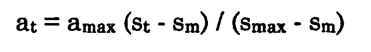
where a
max is the maximum acceleration possible, and s
max is the maximum speed possible on flat ground. For any combination of vehicle speed
and gear ratio, a
max and s
max are fixed, so a
t varies linearly with (s
t-s
m). In any gear ratio, as the instantaneous speed s
m increases towards s
max the target acceleration rate at will decrease for any given value of (s
t - s
m). The characteristics of target acceleration rate as a function of (s
t - s
m) are therefore a series of straight lines, the gradient of which increases with vehicle
speed as shown in Figure 3.
[0017] As shown in Figure 2 there is for each gear a minimum target speed which is set at
such a level that the engine will be running at idle speed, or slightly faster, when
the vehicle is travelling at the minimum target speed. However this has the disadvantage
that the speed control system cannot control the vehicle speed down to very low speeds
or to a standstill. In order to overcome this problem, use can be made of known technology
which provides automatic control of a vehicle clutch to provide controlled gear changes
in a manual-type transmission. Basically this technology controls the engagement of
the clutch automatically in response to movement of the manual gear select lever by
the driver so as to provide a smooth gear change without the need for clutch control
by the driver. The control system for this type of system could be modified so as
to co-operate with the speed control system of the present invention by disengaging
the clutch if the vehicle speed falls below that corresponding to engine idle speed.
This would enable the vehicle speed to be controlled down to zero on a hill descent.
For speed control on flat ground or on ascent of a hill, the system could also be
modified so as to control the engagement of the clutch so as to maintain the target
vehicle speed, whilst keeping the engine speed constant. This again would allow control
for speeds down to zero.
[0018] Referring to Figure 4 in the hill descent mode the speed control unit 22 interprets
the position of the brake pedal 32 as a demand for deceleration. A target deceleration
is defined for each position of the brake pedal, and the rate of deceleration increases
with increasing depression of the brake pedal 32. It then determines the best manner
in which to provide the demanded level of deceleration. Generally engine braking will
be used in preference to use of the disc brakes if it can produce the required level
of braking. However the proportion of braking produced by the power train and the
disc brakes may depend on the speed at which braking is required. In the event of
a demand for sudden braking the disc brakes produce substantially all of the braking
initially because they can respond much faster than the braking from the power train,
but then as the engine braking available increases the braking torque from the disc
brakes is reduced so as to keep the total deceleration at the required level.
[0019] Clearly if only one of the brake and accelerator pedals is depressed by the driver,
the speed control unit 22 can control the speed of the vehicle simply as described
above. However, if both of the pedals are depressed the speed control unit 22 needs
to resolve the conflicting demands of the driver. This can be done in various ways.
[0020] The simplest is to use any demand for deceleration from the brake pedal to over-ride
a demand for acceleration or speed from the accelerator pedal. Then if ever both pedals
are depressed the signal from the accelerator pedal is ignored and the vehicle decelerated
as requested by the position of the brake pedal.
[0021] Another way of resolving the conflicting demands is to 'add together' the two demands
to reach a net demand for acceleration or deceleration, and control the power train
and brakes accordingly, as if the net demand were being given by the driver using
only one of the pedals. This has the advantage that it is closer to what the driver
would expect from a conventional vehicle but avoids the waste of energy caused when
the brakes and power train are operated in conflict with each other.
[0022] Referring to Figure 5 in a variant of the first embodiment, in the hill descent mode,
the speed control unit 22 interprets the brake pedal position as a demand for a specific
braking torque. Therefore for each position of the brake pedal a target braking torque
is defined. The speed control unit then controls the engine 34 and brakes 16 so as
to produce the required braking torque.
[0023] Referring to Figure 6, in a second embodiment of the invention a vehicle includes
an engine 100 for producing drive which is input to a continuously variable transmission
(CVT) 102 from which it is transmitted to the vehicle wheels 104, which have brake
discs 106 connected to them arranged to be acted on by hydraulically operated brake
callipers 108. An electric motor / generator 109 which is operable as a starter motor
for the engine, as a source of tractive drive torque, and as a generator to provide
regenerative braking, is also included in the power train. The fuelling, air supply
and spark timing of the engine are controlled by an engine management system (EMS)
110, the motor / generator 109 is controlled by a motor controller 111, and the ratio
of the CVT is controlled by a CVT controller 112. The EMS 110, motor controller 111,
and the CVT controller 112 are all controlled by a power train controller 114. The
brake fluid pressure to the callipers 108 is controlled by a hydraulic brake control
unit 116 which comprises a valve block controlling the fluid pressure received from
a brake master cylinder 118, operated by a brake pedal 120, and from a pump 122. The
power train controller 114 receives an input from an accelerator pedal potentiometer
124. A speed controller 126 also receives inputs from the accelerator pedal potentiometer
124, a brake pedal accelerometer 126 and a set of wheel speed sensors 130 which enable
it to determine the ground speed of the vehicle.
[0024] Under normal operation the accelerator pedal potentiometer signal is interpreted
by the power train controller 114 as a drive torque demand signal, and the power train
controller provides an input to the EMS and to the CVT controller to request a suitable
engine torque and transmission ratio to achieve the requested drive torque. The brakes
are operated hydraulically at a braking pressure which is controlled directly by the
master cylinder 118, subject to an anti-lock function provided by the hydraulic brake
control and a traction control function provided by the speed control unit 126.
[0025] The speed control unit 126 can, however be switched to a speed control mode in which
the signal from the accelerator pedal potentiometer 124 is interpreted as a speed
demand signal and the signal from the brake pedal potentiometer 128 is interpreted
as a deceleration demand signal. In this case the speed control unit 126 monitors
the vehicle speed, compares it with a target speed and target acceleration or deceleration
which are determined by the position of the accelerator pedal 126 and the brake pedal
126, determines the most appropriate source of the required drive or braking torque,
and sends a torque demand signals to the power train controller 114 or the brake control
unit 116 accordingly.
[0026] In many respects the control of this system is the same as that of the first embodiment.
However with a larger number of sources of driving torque, which can be produced by
the engine or the motor / generator and controlled using the transmission, and braking
torque, which can be produced by the engine or the motor / generator or the brakes
and also controlled using the transmission, the control parameters are clearly different.
For example the level of charging of the battery associated with the motor / generator
needs to be taken into consideration when determining levels of drive or braking torque
the motor / generator can be asked to produce.
[0027] In this embodiment the proportion of braking torque from the various sources can
be varied with time as in the first embodiment so as to make use of their various
characteristics. For example if the driver applied the brake pedal 120 suddenly so
as to demand a deceleration of 0.25g the brakes 106, 108 would provide this almost
instantneously before any assistance could be provided by the motor 109. Then as the
level of regenerative braking available from the motor 109 increases this is used
increasingly instead of the brakes, whilst keeping the total level of braking constant
as required by the driver. Finally the regenerative braking can provide the braking
without any assistance from the brakes.
[0028] Whilst the embodiments described above both include hydraulic brake systems it will
be apparent that electrically actuated brakes, as used in so called 'brake by wire'
systems, could easily be controlled so as to form part of a similar system.
1. A vehicle speed control system comprising, driving means (34, 36;100, 109) arranged
to produce drive for the vehicle, braking means (14, 16, 20; 108, 116) arranged to
produce braking of the vehicle, vehicle speed measuring means (24, 26, 130) for measuring
the speed of the vehicle, speed control means (22, 126), driver operated acceleration
demand means (30, 31; 124) and driver operated deceleration demand means (32, 33;
120, 128), the speed control means (22, 126) being arranged to receive signals from
the two demand means (31, 33; 124, 128) and to control the driving means (34, 36;100,
109) and the braking means (14, 16, 20; 108, 116) so as to produce the demanded level
of acceleration or deceleration, characterized in that the speed control means (22, 126) is arranged such that each of a range of positions
of the acceleration demand means (31, 124) has a target speed associated with it such
that when the acceleration demand means (31, 124) is in each said position the braking
means (14, 16, 20; 108, 116) and the driving means (34, 36;100, 109) are controlled
so as to bring the vehicle speed towards the associated target speed, and, at least
over a range of positions of the deceleration demand means (32, 33; 120, 128), the
speed control means (22, 126) is arranged to define for each position of the deceleration
demand means a target deceleration rate and control the driving means (34, 36;100,
109) and the braking means (14, 16, 20; 108, 116) so as to decelerate the vehicle
at the target deceleration rate.
2. A system according to claim 1 wherein the rate at which the vehicle speed is brought
towards the target speed is controlled so as to vary in a predefined manner with the
difference between the measured speed of the vehicle and the target speed.
3. A system according to claim 2 wherein the rate at which the vehicle speed is brought
towards the target speed is controlled so as to increase as the difference between
the target speed and the measured speed of the vehicle increases.
4. A system according to claim 2 or claim 3 wherein the speed control means (22, 126)
is arranged to measure the difference between the target speed and the measured speed
and to control the acceleration of the vehicle towards a target acceleration rate
which is determined by said difference.
5. A system according to any foregoing claim wherein the speed control means (22, 126)
is arranged to define a target braking torque which is dependent on the position of
the deceleration demand means (32, 33; 120, 128) and to control the driving means
(34, 36; 100, 109) and the braking means (14, 16, 20; 108, 116) so as to apply the
demanded torque to the vehicle wheels.
6. A system according to claim 5 wherein, at least over a range of positions of the deceleration
demand means, the speed control means (22, 126) is arranged to define for each position
of the deceleration demand means a target braking torque and to control the driving
means and the braking means so as to produce the demanded braking torque.
7. A system according to any foregoing claim further comprising a drive control means
arranged to control the driving means and wherein the speed control means is arranged
to produce a torque demand signal indicative of the torque required from the driving
means, and the drive control means is arranged to control the driving means so as
to produce the required torque.
8. A system according to any foregoing claim wherein the driving means is operable to
produce a braking torque and the speed control means is arranged to co-ordinate operation
of the driving means and the braking means to provide braking of the vehicle.
9. A system according to claim 8 wherein the driving means includes an engine (34; 100)
and the speed control means (22, 126) is arranged to control the engine (34; 100)
so as to produce engine braking and driving torque as required.
10. A system according to claim 8 wherein the driving means includes an electric motor
(109) and the speed control means (126) is arranged to control the motor (109) so
as to produce regenerative braking and driving torque as required.
11. A system according to any one of claims 8 to 10 wherein the driving means includes
a transmission (102) having a variable drive ratio and the speed control means (126)
is arranged to control the transmission (102) so as to control braking torque and
driving torque as required.
12. A system according to any foregoing claim wherein the speed control means (22) is
operable in a first mode in which each of said positions of the acceleration demand
means (30, 31) has a target speed associated with it, and a second mode in which each
of said positions has a drive torque associated with it and the speed control means
(22) is arranged to control the driving means (34) to produce the demanded torque
substantially independently of the vehicle speed.
13. A system according to claim 12 wherein in the first mode the speed control means (22)
is arranged to control the driving means (34) such that the rate at which the vehicle
speed is brought towards the target speed is controlled so as to vary in a predefined
manner with the difference between the measured speed of the vehicle and the target
speed.
14. A system according to claim 12 or claim 13 wherein the target speed associated with
each of said range of positions of the acceleration demand means (30, 31) in the first
mode corresponds to the speed at which the vehicle would travel on a flat surface
with the speed control input member in that position if the speed control means were
in the second mode.
1. Fahrgeschwindigkeits-Steuersystem, das enthält: Antriebsmittel (34, 36; 100, 109),
die dafür ausgelegt sind, einen Antrieb für das Fahrzeug zu erzeugen, Bremsmittel
(14, 16, 20; 108, 116), die dafür ausgelegt sind, eine Bremsung des Fahrzeugs zu erzeugen,
Fahrgeschwindigkeits-Messmittel (24, 26, 130) zum Messen der Geschwindigkeit des Fahrzeugs,
Geschwindigkeitssteuermittel (22, 126), fahrerbetätigte Beschleunigungsanforderungsmittel
(30, 31; 124) und fahrerbetätigte Verzögerungsanforderungsmittel (32, 33; 120, 128),
wobei die Geschwindigkeitsteuermittel (22, 126) so ausgelegt sind, dass sie Signale
von den zwei Anforderungsmitteln (31, 33; 124, 128) empfangen und die Antriebsmittel
(34, 36; 100, 109) und die Bremsmittel (14, 16, 20; 108, 116) in der Weise steuern,
dass sie den angeforderten Beschleunigungsgrad oder Verzögerungsgrad erzeugen, dadurch gekennzeichnet, dass die Geschwindigkeitssteuermittel (22, 126) so ausgelegt sind, dass jeder aus einem
Bereich von Stellungen der Beschleunigungsanforderungsmittel (31, 124) eine Sollgeschwindigkeit
in der Weise zugeordnet ist, dass dann, wenn die Beschleunigungsanforderungsmittel
(31, 124) in jeder dieser Stellung sind, die Bremsmittel (14, 16, 20; 108, 116) und
die Antriebsmittel (34, 36; 100, 109) in der Weise gesteuert werden, dass die Fahrgeschwindigkeit
auf die zugeordnete Sollgeschwindigkeit gebracht wird, und wobei wenigstens über einen
Bereich von Stellungen der Verzögerungsanforderungsmittel (32, 33; 120, 128) die Geschwindigkeitssteuermittel
(22, 126) so ausgelegt sind, dass sie für jede Stellung der Verzögerungsanforderungsmittel
eine Sollverzögerungsrate definieren und die Antriebsmittel (34, 36; 100, 109) und
die Bremsmittel (14, 16, 20; 108, 116) in der Weise steuern, dass das Fahrzeug mit
einer Sollverzögerungsrate verzögert wird.
2. System nach Anspruch 1, wobei die Rate, mit der die Fahrgeschwindigkeit auf die Sollgeschwindigkeit
gebracht wird, in der Weise gesteuert wird, dass sie sich in einer vordefinierten
Weise mit der Differenz zwischen der gemessenen Geschwindigkeit des Fahrzeugs und
der Sollgeschwindigkeit ändert.
3. System nach Anspruch 2, wobei die Rate, mit der die Fahrgeschwindigkeit auf die Sollgeschwindigkeit
gebracht wird, in der Weise gesteuert wird, dass sie sich erhöht, während sich die
Differenz zwischen der Sollgeschwindigkeit und der gemessenen Geschwindigkeit des
Fahrzeugs erhöht.
4. System nach Anspruch 2 oder Anspruch 3, wobei die Geschwindigkeitssteuermittel (22,
126) so ausgelegt sind, dass sie die Differenz zwischen der Sollgeschwindigkeit und
der gemessenen Geschwindigkeit messen und die Beschleunigung des Fahrzeugs auf eine
Sollbeschleunigungsrate steuern, die durch die Differenz bestimmt ist.
5. System nach einem vorangehenden Anspruch, wobei die Geschwindigkeitssteuermittel (22,
126) so ausgelegt sind, dass sie ein Sollbremsdrehmoment definieren, das von der Stellung
der Verzögerungsanforderungsmittel (32, 33; 120, 128) abhängt, und die Antriebsmittel
(34, 36; 100, 109) und die Bremsmittel (14, 16, 20; 108, 116) in der Weise steuern,
dass auf die Fahrzeugräder das angeforderte Drehmoment angewendet wird.
6. System nach Anspruch 5, wobei die Geschwindigkeitssteuermittel (22, 126) so ausgelegt
sind, dass sie wenigstens über einen Bereich von Stellungen der Verzögerungsanforderungsmittel
für jede Stellung der Verzögerungsanforderungsmittel ein Sollbremsdrehmoment definieren
und die Antriebsmittel und die Bremsmittel in der Weise steuern, dass das angeforderte
Bremsdrehmoment erzeugt wird.
7. System nach einem vorstehenden Anspruch, das ferner Antriebssteuermittel aufweist,
die so ausgelegt sind, dass sie die Antriebsmittel steuern, und wobei die Geschwindigkeitssteuermittel
so ausgelegt sind, dass sie ein Drehmoment-Anforderungssignal erzeugen, das das von
den Antriebsmitteln angeforderte Drehmoment angibt, und wobei die Antriebssteuermittel
so ausgelegt sind, dass sie die Antriebsmittel in der Weise steuern, dass sie das
geforderte Drehmoment erzeugen.
8. System nach einem vorstehenden Anspruch, wobei die Antriebsmittel so betreibbar sind,
dass sie ein Bremsdrehmoment erzeugen, und wobei die Geschwindigkeitssteuermittel
so ausgelegt sind, dass sie den Betrieb der Antriebsmittel und der Bremsmittel so
koordinieren, dass eine Bremsung des Fahrzeugs bereitgestellt wird.
9. System nach Anspruch 8, wobei die Antriebsmittel eine Maschine (34; 100) umfassen
und wobei die Geschwindigkeitssteuermittel (22, 126) so ausgelegt sind, dass sie die
Maschine (34; 100) in der Weise steuern, dass eine Maschinenbremsung und ein Antriebsdrehmoment
nach Bedarf erzeugt werden.
10. System nach Anspruch 8, wobei die Antriebsmittel einen Elektromotor (109) umfassen
und wobei die Geschwindigkeitssteuermittel (126) so ausgelegt sind, dass sie den Motor
(109) in der Weise steuern, dass eine Rückgewinnungsbremsung und ein Antriebsdrehmoment
nach Bedarf erzeugt werden.
11. System nach einem der Ansprüche 8 bis 10, wobei die Antriebsmittel ein Getriebe (102)
mit einem veränderlichen Antriebsübersetzungsverhältnis umfassen und wobei die Geschwindigkeitssteuermittel
(126) so ausgelegt sind, dass sie das Getriebe (102) in der Weise steuern, dass das
Bremsdrehmoment und das Antriebsdrehmoment nach Bedarf gesteuert werden.
12. System nach einem vorstehenden Anspruch, wobei die Geschwindigkeitssteuermittel (22)
in einer ersten Betriebsart, in der jeder der Stellungen der Beschleunigungsanforderungsmittel
(30, 31) eine Sollgeschwindigkeit zugeordnet ist, und in einer zweiten Betriebsart,
in der jeder der Stellungen ein Antriebsdrehmoment zugeordnet ist, betreibbar sind
und die Geschwindigkeitssteuermittel (22) so ausgelegt sind, dass sie die Antriebsmittel
(34) zum Erzeugen des angeforderten Drehmoments im Wesentlichen unabhängig von der
Fahrgeschwindigkeit steuern.
13. System nach Anspruch 12, wobei die Geschwindigkeitssteuermittel (22) so ausgelegt
sind, dass sie die Antriebsmittel (34) in der ersten Betriebsart in der Weise steuern,
dass die Rate, mit der die Fahrgeschwindigkeit auf die Sollgeschwindigkeit gebracht
wird, so gesteuert wird, dass sie sich in einer vordefinierten Weise mit der Differenz
zwischen der gemessenen Geschwindigkeit des Fahrzeugs und der Sollgeschwindigkeit
ändert.
14. System nach Anspruch 12 oder Anspruch 13, wobei die jedem Bereich von Stellungen der
Beschleunigungsanforderungsmittel (30, 31) zugeordnete Sollgeschwindigkeit in der
ersten Betriebsart der Geschwindigkeit entspricht, mit der sich das Fahrzeug auf einer
flachen Oberfläche mit dem Geschwindigkeitssteuerungs-Eingabeelement in dieser Stellung
bewegen würde, falls die Geschwindigkeitssteuermittel in der zweiten Betriebsart wären.
1. Système de commande de la vitesse d'un véhicule comprenant des moyens d'entraînement
(34, 36 ; 100, 109) prévus pour produire un entraînement du véhicule, des moyens de
freinage (14, 16, 20 ; 108, 116) prévus pour produire un freinage du véhicule, des
moyens de mesure de la vitesse du véhicule (24, 26, 130) prévus pour mesurer la vitesse
du véhicule, des moyens de régulation de la vitesse (22, 126), des moyens de demande
d'accélération (30, 31; 124) actionnés par le conducteur, et des moyens de demande
de décélération (32, 33 ; 120, 128) actionnés par le conducteur, les moyens de régulation
de la vitesse (22, 126) étant prévus pour recevoir des signaux des deux moyens de
demande (31, 33 ; 124, 128) et pour commander les moyens d'entraînement (34, 36 ;
100, 109) et les moyens de freinage (14, 16, 20 ; 108, 116) de manière à produire
le niveau demandé d'accélération ou de décélération, caractérisé en ce que le moyen de régulation de la vitesse (22, 126) est prévu de telle sorte que chacune
des plage de positions du moyen de demande d'accélération (31, 124) soit associée
à une vitesse cible de sorte que lorsque le moyen de demande d'accélération (31, 124)
est dans chaque dite position, les moyens de freinage (14, 16, 20 ; 108, 116) et les
moyens d'entraînement (34, 36; 100, 109) soient commandés de manière à amener la vitesse
du véhicule vers la vitesse cible associée, et, au moins sur une plage de positions
du moyen de demande de décélération (32, 33 ; 120, 128), le moyen de régulation de
la vitesse (22, 126) est prévu pour définir, pour chaque position du moyen de demande
de décélération, un taux de décélération cible et pour commander les moyens d'entraînement
(34, 36; 100, 109) et les moyens de freinage (14, 16, 20; 108, 116) de manière à décélérer
le véhicule au taux de décélération cible.
2. Système selon la revendication 1, dans lequel le taux auquel la vitesse du véhicule
est amenée à la vitesse cible est commandé de manière à varier de façon prédéterminée
en fonction de la différence entre la vitesse mesurée du véhicule et la vitesse cible.
3. Système selon la revendication 2, dans lequel le taux auquel la vitesse du véhicule
est amenée à la vitesse cible est commandé de manière à augmenter à mesure que la
différence entre la vitesse cible et la vitesse mesurée du véhicule augmente.
4. Système selon la revendication 2 ou 3, dans lequel le moyen de régulation de la vitesse
(22, 126) est prévu pour mesurer la différence entre la vitesse cible et la vitesse
mesurée et pour commander l'accélération du véhicule vers un taux d'accélération cible
qui est déterminé par ladite différence.
5. Système selon l'une quelconque des revendications précédentes, dans lequel le moyen
de régulation de la vitesse (22, 126) est prévu pour définir un couple de freinage
cible qui dépend de la position du moyen de demande de décélération (32, 33 ; 120,
128) et pour commander le moyen d'entraînement (34, 36 ; 100, 109) et le moyen de
freinage (14, 16, 20 ; 108, 116) de manière à appliquer le couple demandé aux roues
du véhicule.
6. Système selon la revendication 5, dans lequel, au moins sur une plage de positions
du moyen de demande de décélération, le moyen de régulation de la vitesse (22, 126)
est prévu pour définir pour chaque position du moyen de demande de décélération, un
couple de freinage cible et pour commander le moyen d'entraînement et le moyen de
freinage de manière à produire le couple de freinage demandé.
7. Système selon l'une quelconque des revendications précédentes, comprenant en outre
un moyen de commande d'entraînement prévu pour commander le moyen d'entraînement et
dans lequel le moyen de régulation de la vitesse est prévu pour produire un signal
de demande de couple indiquant le couple requis par le moyen d'entraînement, et le
moyen de commande d'entraînement est prévu pour commander le moyen d'entraînement
de manière à produire le couple requis.
8. Système selon l'une quelconque des revendications précédentes, dans lequel le moyen
d'entraînement peut être actionné pour produire un couple de freinage et le moyen
de régulation de la vitesse est prévu pour coordonner l'actionnement du moyen d'entraînement
et du moyen de freinage pour assurer le freinage du véhicule.
9. Système selon la revendication 8, dans lequel le moyen d'entraînement comporte un
moteur (34 ; 100) et le moyen de régulation de la vitesse (22, 126) est prévu pour
commander le moteur (34 ; 100) de manière à produire un couple de freinage et d'entraînement
moteur comme requis.
10. Système selon la revendication 8, dans lequel le moyen d'entraînement comporte un
moteur électrique (109) et le moyen de régulation de la vitesse (126) est prévu pour
commander le moteur (109) de manière à produire un couple régénératif de freinage
et d'entraînement comme requis.
11. Système selon l'une quelconque des revendications 8 à 10, dans lequel le moyen d'entraînement
comporte une transmission (102) ayant un rapport d'entraînement variable et le moyen
de régulation de la vitesse (126) est prévu pour commander la transmission (102) de
manière à commander le couple de freinage et le couple d'entraînement comme requis.
12. Système selon l'une quelconque des revendications précédentes, dans lequel le moyen
de régulation de la vitesse (22) peut fonctionner dans un premier mode dans lequel
chacune desdites positions du moyen de demande d'accélération (30, 31) est associée
à une vitesse cible, et dans un deuxième mode dans lequel chacune desdites positions
est associée à un couple d'entraînement et le moyen de régulation de la vitesse (22)
est prévu pour commander le moyen d'entraînement (34) pour produire le couple demandé
substantiellement indépendamment de la vitesse du véhicule.
13. Système selon la revendication 12, dans lequel, dans le premier mode, le moyen de
régulation de la vitesse (22) est prévu pour commander le moyen d'entraînement (34)
de telle sorte que le taux auquel la vitesse du véhicule est amenée vers la vitesse
cible soit commandé de manière à varier de façon prédéterminée en fonction de la différence
entre la vitesse mesurée du véhicule et la vitesse cible.
14. Système selon la revendication 12 ou 13, dans lequel la vitesse cible associée à chaque
position dans ladite plage de positions du moyen de demande d'accélération (30, 31)
dans le premier mode correspond à la vitesse à laquelle le véhicule se déplacerait
sur une surface plane avec l'organe d'entrée de régulation de la vitesse dans cette
position si le moyen de régulation de la vitesse était dans le deuxième mode.
REFERENCES CITED IN THE DESCRIPTION
This list of references cited by the applicant is for the reader's convenience only.
It does not form part of the European patent document. Even though great care has
been taken in compiling the references, errors or omissions cannot be excluded and
the EPO disclaims all liability in this regard.
Patent documents cited in the description