| (19) |
 |
|
(11) |
EP 1 281 874 B1 |
| (12) |
EUROPEAN PATENT SPECIFICATION |
| (45) |
Mention of the grant of the patent: |
|
11.07.2007 Bulletin 2007/28 |
| (22) |
Date of filing: 30.05.2002 |
|
| (51) |
International Patent Classification (IPC):
|
|
| (54) |
Threaded fastener
Befestigungselement mit Gewinde
Elément de fixation fileté
|
| (84) |
Designated Contracting States: |
|
DE FR GB |
| (30) |
Priority: |
31.07.2001 US 918656
|
| (43) |
Date of publication of application: |
|
05.02.2003 Bulletin 2003/06 |
| (73) |
Proprietor: ILLINOIS TOOL WORKS INC. |
|
Glenview,
Cook County,
Illinois 60025 (US) |
|
| (72) |
Inventors: |
|
- Kram, Guenther Reinhard
Bartlett,
Illinois 60103 (US)
- Chen, Chin-Tsai
Dan Shuei, Taipei Country 251 (TW)
|
| (74) |
Representative: Bloch, Gérard et al |
|
Cabinet Bloch & Associés
23bis, rue de Turin
75008 Paris
75008 Paris (FR) |
| (56) |
References cited: :
EP-A- 1 001 178
US-A- 1 802 560
|
FR-A- 324 614
US-A- 6 086 302
|
|
| |
|
|
|
|
| |
|
| Note: Within nine months from the publication of the mention of the grant of the European
patent, any person may give notice to the European Patent Office of opposition to
the European patent
granted. Notice of opposition shall be filed in a written reasoned statement. It shall
not be deemed to
have been filed until the opposition fee has been paid. (Art. 99(1) European Patent
Convention).
|
[0001] The present invention relates generally to threaded fasteners, and more particularly
to a new and improved threaded fastener which has uniquely formed or fabricated saw-tooth
or serrated-teeth structure integrally formed upon the peripheral edge regions of
the crest portions of the lead threads of the fastener whereby the cutting performance
or characteristics of the lead threads is enhanced so as to in turn facilitate and
enhance the penetration or insertion rate of the fastener into a substrate, as well
as the pullout resistance of the fastener, and still further, the new and improved
fastener is well-adapted for threaded insertion within a plurality of different substrates,
such as, for example, wood, metal, composite materials, concrete, or the like. In
connection with the fabrication or manufacture of threaded fasteners, a multiplicity
of different fasteners are of course well-known and are accordingly available in the
marketplace: More particularly, or furthermore, the multiplicity or different varieties
of threaded fasteners have been developed in accordance with various objectives, such
as, for example, to enable the fasteners to achieve predetermined desired insertion
and withdrawal torque characteristics, to enable the fasteners to be used in conjunction
with different mounting panels, support surfaces, or substrates comprising different
types of materials, to enable the fasteners to exhibit predetermined desired pull-out
resistance values with respect to such panels, surfaces, or substrates, and the like.
Accordingly, the threads of such fasteners are usually provided with supplemental
or auxiliary structure, which seeks to achieve the aforenoted objectives. For example,
as disclosed within
United States Patent 5,110,245 which issued to Hiroyuki on May 5, 1992, the peripheral edge portions of the threads of the threaded fasteners 1 disclosed
therein are provided with slot recesses 6 in order to render the fasteners 1 suitable
for enhanced stability within thermoplastic resin substrates. In a similar manner,
as disclosed within
United States Patent 5,044,853 which issued to Dicke on September 3, 1991, the peripheral edge portions of the threaded fastener are provided with parabolic
depressions wherein the dispositions of the depressions are effectively skewed such
that the insertion torque is less than the withdrawal torque thereby rendering the
screwing of the fastener into the particular substrate relatively easier than the
unscrewing of the fastener from the substrate. Lastly, as disclosed within
United States Patent 4,637,767 which issued to Yaotani et al. on January 20, 1987, the threads of the fastener are provided with projections 150 so as to optimise
torque levels as well as pull-out resistance values. While the aforenoted exemplary
threaded fasteners have performed satisfactorily and have accordingly been commercially
successful, a need still exists in the art for a new and improved threaded fastener
which will have new and improved structure integrally incorporated within the lead
thread portions thereof whereby such lead threads can effectively cut into a diverse
type of substrates in a relatively faster and smoother manner, such as, for example,
wood, metal, composite materials, concrete, or the like. In addition, the lead threads
can effectively cause the removal of cut material and the dispersal of the same so
as to permit the following or trailing threads to easily traverse the newly formed
threads which have been tapped into the substrates by means of the newly structured
lead threads, and wherein, as a result of such new and improved screw fastener thread
structure, the screw fastener will exhibit enhanced tapping or insertion torque characteristics,
enhanced tapping and insertion speed, and improved pull-out resistance properties.
Accordingly, it is an object of the present invention to provide a new and improved
threaded screw fastener. Another object of the present invention is to provide a new
and improved threaded screw fastener which effectively overcomes the various disadvantages
and drawbacks characteristic of PRIOR ART threaded screw fasteners. An additional
object of the present invention is to provide a new and improved threaded screw fastener
which has new and improved cutting structure integrally incorporated within the peripheral
crest regions of the leading threads such that the new and improved threaded screw
fastener is uniquely adapted for use in conjunction with a multiplicity of different
types of substrates such as, for example, wood, metal, composites, concrete, or the
like. A further object of the present invention is to provide a new and improved threaded
screw fastener which has new and improved cutting structure integrally incorporated
within the peripheral crest regions of the leading threads such that the new and improved
threaded screw fastener is uniquely adapted for actually cutting, removing, and dispersing
material from the particular substrate during the performance of a tapping operation.
A last object of the present invention is to provide a new and improved threaded screw
fastener which has new and improved cutting structure integrally incorporated within
the peripheral crest regions of the leading threads such that the new and improved
threaded screw fastener is uniquely adapted for actually cutting, removing, and dispersing
material from the particular substrate during the performance of a tapping operation
such that torque insertion requirements are diminished, insertion speed is enhanced,
and pull-out resistance properties are improved.
[0002] The foregoing and other objectives are achieved in accordance with the teachings
and principles of the present invention through the provision of a new and improved
threaded screw fastener according to claim 1.
[0003] The serrated teeth thus serve, in effect, as saw-blade type teeth which actually
cut threads into the substrate walls, as opposed to in effect simply moving substrate
material from the tapped regions, and the thread structure also serves to remove and
disperse the cut debris such that the following or trailing thread portions can smoothly
and quickly traverse the previously tapped threads. In this manner, the insertion
torque level and installation time are substantially reduced, and still further, the
fastener exhibits enhanced pull-out resistance values.
[0004] It should be noted that none of the fasteners of
EP-A-1001178,
FR-A-3246 14,
US-A-6086302 and
US-A-1802 560 is capable of cutting and removing material from the side wall portions of a bore
in any one of a plurality of different substrates, with a fast and smooth insertion,
with a reduced insertion torque and with an enhanced pull-out resistance.
[0005] Moreover, in view of the teaching of
EP-A-1001178, the fastener of the instant case can be universally used.
[0006] In view of the teaching of
US-A-5674035, related to a fastener with a relatively complex teeth configuration, the fastener
of the instant case is easy to manufacture and capable to better displace debris.
[0007] Various other objects, features, and attendant advantages of the present invention
will be more fully appreciated from the following detailed description when considered
in connection with the accompanying drawings in which like reference characters designate
like or corresponding parts throughout the several views, and wherein:
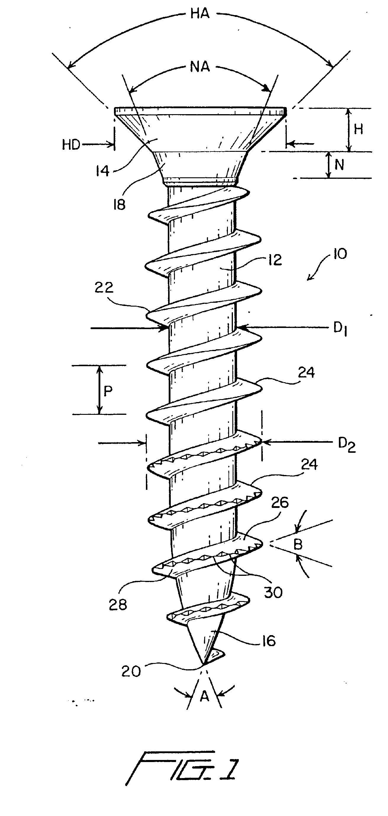
FIGURE 1 is a vertical front elevational view of a new and improved threaded screw
fastener constructed in accordance with the principles and teachings of the present
invention wherein the lead threads of the screw fastener are provided with the plurality
of unique and novel, circumferentially arranged saw-blade type teeth upon the other
peripheral edge regions of the lead thread crest portions; and
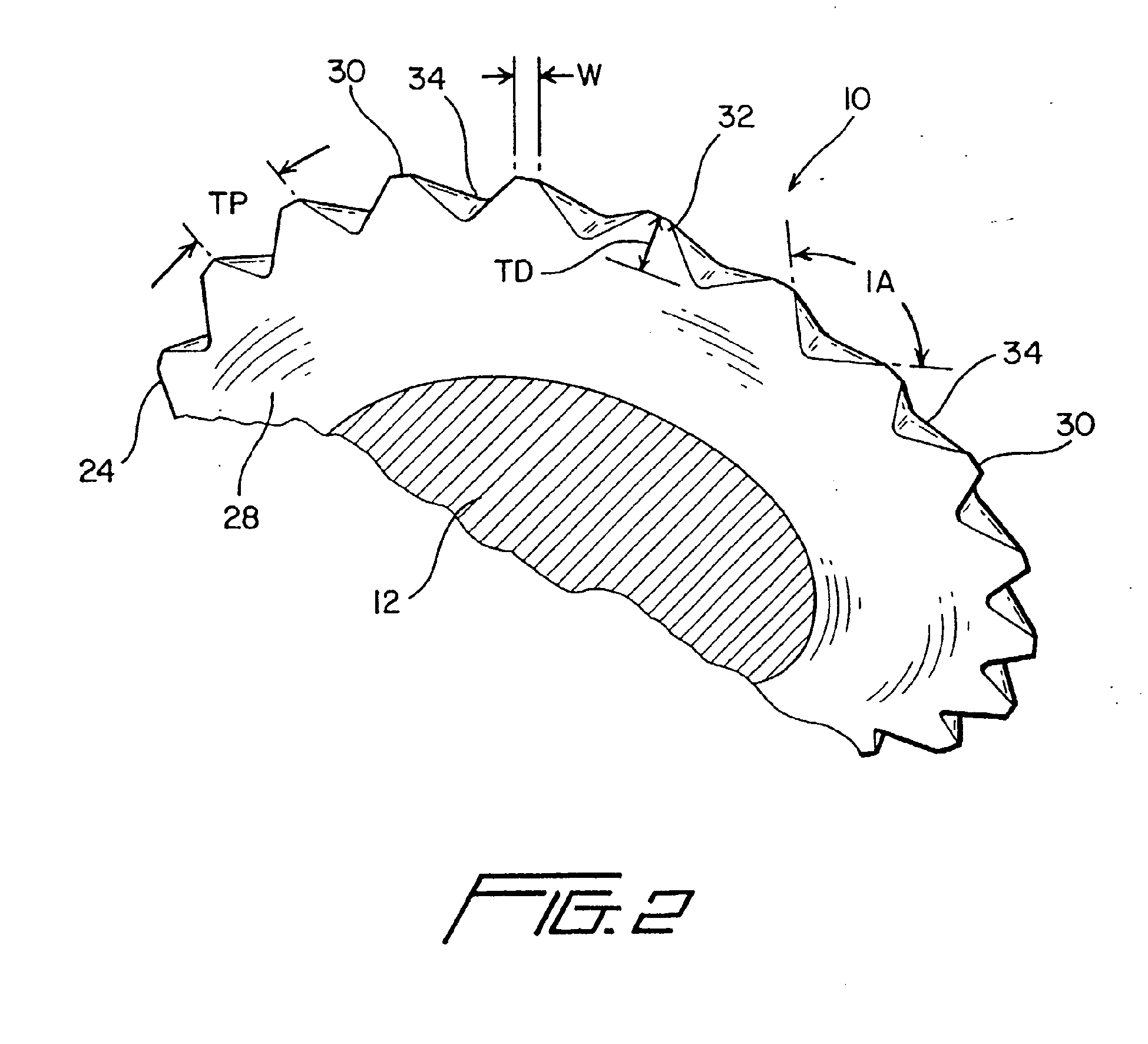
FIGURE 2 is an enlarged, partial cross-sectional, bottom perspective view of a lead
thread portion of the new and improved threaded screw fastener shown in FIGURE 1,
wherein the details of the saw-blade type teeth, integrally formed upon the other
peripheral edge regions of the lead thread crest portions of the single continuous
helical thread formed upon the threaded screw fastener so as to achieve the advantageous
torque, insertion, and pull-out resistance properties characteristic of the present
invention, are particularly illustrated.
[0008] Referring now to the drawings, and more particularly to FIGURE 1 thereof, a new and
improved threaded screw fastener, constructed in accordance with the principles and
teachings of the present invention wherein the lead threads of the screw fastener
are provided with the plurality of unique and novel, circumferentially arranged saw-blade
type teeth upon the outer peripheral edge regions of the lead thread crest portions
so as to achieve reduced insertion torque characteristics rendering the insertion
or installation procedure quicker and faster, as well as enhancing pull-out resistance
values, is disclosed and is generally indicated by the reference character 10. More
particularly, the threaded screw fastener 10 comprises a shank portion 12 of substantially
constant diameter Di, and a tapered head portion 14 formed upon the upper end of the
shank portion 12, wherein the tapered head portion 14 has an axial depth or thickness
H,.a diametrical extent HD, and an included taper angle HA of approximately 85-90°.
A pointed tip portion 16 is formed upon the lower end of the shank portion 12, and
a tapered neck portion 18 integrally interconnects the tapered head portion 14 of
the fastener 10 to the upper end of the shank portion 12. The tapered neck portion
18 has an axial depth or thickness N and an included taper angle NA of approximately
48-52°, and it is noted that the pointed tip portion 16 comprises an end point 20
at which diametrically opposite sides or planes of the pointed tip portion 16 effectively
intersect each other at an angle A which is within the range of 20-25°. A single continuous
helical thread 22 is formed upon the shank and tip portions 12,16 of the fastener
10, and it is noted that the individual threads 24, comprising the overall single
continuous helical thread 22 and which are formed upon the constant diameter portion
D
1 of the shank portion 12 so as to have a pitch P defined there between, have an external
crest diameter dimension D
2. Still further, it is noted that each one of the individual threads 24 comprises
an upper flank or surface 26 and a lower flank or surface 28 wherein planes defined
within the upper and lower flanks or surfaces 26, 28 effectively intersect each other
at an angle B which is within the range of 30-50°, and preferably has a value of 40°.In
accordance with the principles and teachings of the present invention, it is further
seen from FIGURE 1, and as may best be seen from FIGURE 2, that the individual leading
threads 24 of the threaded screw fastener 10 are provided with unique and novel structure
comprising a series of .saw-blade type or serrated teeth 30 which are integrally formed
upon the outer peripheral edge regions of the leading thread crest portions 32 of
the single continuous helical thread 22 formed upon the threaded screw fastener 10
so as to enable or facilitate achievement of the advantageous insertion, torque, and
pull-out resistance properties characteristic of the new and improved threaded screw
fastener 10. It is to be initially noted that, in connection with the provision of
such unique and novel structure comprising the series of saw-blade type teeth 30 integrally
formed upon the outer peripheral edge regions of the leading thread crest portions
32 of the single continuous helical thread 22 formed upon the threaded screw fastener
10, and in view of the additional fact that the threaded screw fastener 10 may have
any suitable longitudinal or axial length dimension, such as, for example, between
0.625 inches and 3.50 inches, the saw-blade type teeth 30 are provided upon those
individual leading threads 24 which are disposed within approximately the leading
one-third or one-half axial extent of the threaded screw fastener 10 as measured from
the pointed tip 20 to the head portion 14. with reference therefore now being specifically
made to FIGURE 2, the detailed structure of the unique and novel series of saw-blade
type teeth 30, as integrally formed upon the outer peripheral edge regions of the
leading thread crest portions 32 of the single continuous helical thread 22 formed
upon the threaded screw fastener 10, will now be described. More particularly, it
is seen that as a result of the use of suitably specific tooling, not shown, but which
may be, for example, a suitable rolling die, the outer peripheral edge regions of
the leading thread crest portions 32 of the single continuous helical thread 22 have
25 the continuous series or set of saw-blade teeth 30 formed therein such that valley
regions 34 interposed between adjacent ones of the saw-blade teeth 30 are defined
by means of an included angle IA of approximately 100°. In addition, it is further
noted that the tooth pitch TP, or in other words, the circumferential distance defined
between adjacent saw-blade teeth 30, will have predetermined values, as will be noted
hereinafter in connection with several fabricated examples of the new and improved
threaded screw fastener 10 of the present invention, depending upon the particular
diametrical size of the fastener 10, and in a similar manner, each one of the saw-blade
teeth 30 will have a predetermined depth dimension TD, that is, the radial distance
defined between the radially outermost tip of each tooth 30 to the base of each tooth
30, which will also accordingly vary depending upon the particular diametrical size
of the fastener 10. It is lastly noted that each saw-blade tooth 30 can have a predeterminedly
dimensioned width W, as measured in the peripheral or circumferential direction, which
can be optimally varied so as to in fact achieve different degrees of cutting efficiency
depending upon the particular substrate material into which the self-tapping fasteners
10 are being inserted.
[0009] As has been noted above, various conventionally sized threaded screw fasteners can
have the unique and novel saw-blade teeth 30, constructed in accordance with the principles
and teachings of the present invention, incorporated therein, and accordingly, the
following examples of fasteners 10, provided with the saw-blade teeth 30 of the present
invention, are set forth wherein the particular structural 25 and size characteristics
of the saw-blade teeth 30, and their interoperative cooperation, will become readily
apparent:
| EXAMPLE 1- A NUMBER 6 |
SIZED SCREW FASTENER |
| Head Diameter - |
HD - |
6.40-6.80 mm |
| Head Thickness - |
H - |
2.20 mm |
| Neck Thickness - |
N - |
1.40 mm |
| Shank Diameter - |
D1 - |
2.20 mm |
| Thread Crest Diameter - |
D2 - |
3.30-3.60 mm |
| Thread Pitch |
p - |
1.80 mm |
| Saw-Blade Teeth Pitch - |
TP - |
0.60 |
| Saw-Blade Teeth Depth - |
TD - |
0.21 mm |
| Saw-Blade Teeth Included Angle - |
IA - |
100 Degrees |
| EXAMPLE 2 A NUMBER 8 |
SIZED SCREW FASTER |
| Head Diameter - |
HD |
7.70-8.10 mm |
| Head Thickness - |
H |
2.50 mm |
| Neck Thickness - |
N |
1.60 mm |
| Shank Diameter - |
D1 |
2.40 mm |
| Thread Crest Diameter - |
D2 |
3.80-4.10 mm |
| Thread Pitch - |
p |
2.00 mm |
| Saw-Blade Teeth.Pitch - |
TP |
0.60 mm |
| Saw-Blade Teeth Depth - |
TD |
0.21 mm |
| Saw-Blade Teeth Included Angle - |
IA |
100 Degrees |
| EXAMPLE 3 - A NUMBER 10 |
SIZED SCREW FASTENER |
| Head Diameter - |
HD - |
9.10-9.50 mm |
| Head Thickness - |
H - |
2.80 mm |
| Neck Thickness - |
N - |
1.80 mm |
| Shank Diameter - |
Di - |
3.03 mm |
| Thread Crest Diameter - |
D2 - |
4.80-5.10 mm |
| Thread Pitch - |
P - |
2.60 mm |
| Saw-Blade Teeth Pitch - |
TP - |
0.70 mm |
| Saw-Blade Teeth Depth - |
TD - |
0.25 mm |
| Saw-Blade Teeth IncludedAngle - |
IA - |
100 Degrees |
| EXAMPLE 4 - A NUMBER 12 |
SIZED SCREW FASTENER |
| Head Diameter - |
HD - |
10.30-10.80 mm |
| Head Thickness - |
H - |
3.10 mm |
| Neck Thickness - |
N - |
2.00 mm |
| Shank Diameter - |
D1 - |
3.30 mm |
| Thread Crest Diameter - |
D2 - |
5.30-5.60 mm |
| Thread Pitch - |
P - |
2.90 mm |
| Saw-Blade Teeth Pitch - |
TP - |
0.70 mm |
| Saw-Blade Teeth*Depth - |
TD - |
0.25 mm |
| Saw-Blade Teeth Included Angle - |
IA - |
100 Degrees |
| EXAMPLE 5 A NUMBER 14 |
SIZED SCREW FASTENER |
| Head Diameter - |
HD- |
11.90-12.40 mm |
| Head Thickness - |
H |
3.40 mm |
| Neck Thickness - |
N - |
2.20 mm |
| Shank Diameter - |
D1 - |
3.60mm |
| Thread Crest Diameter - |
DZ - |
5.80-6.10 mm |
| Thread Pitch - |
P - |
3.10 mm |
| Saw-Blade Teeth Pitch - |
TP - |
0.80 mm |
| Saw-Blade Teeth Depth - |
TD - |
0.29 mm |
| Saw-Blade Teeth Included Angle - |
IA - |
100 Degrees |
[0010] In connection with any one of the aforenoted examples of threaded screw fasteners
10 which may be fabricated in accordance with the principles and teachings of the
present invention, it is to be emphasized that as a result of the provision of the
continuous series of saw-blade teeth 30 upon the outer peripheral edge regions of
the leading thread crest portions 32 of the single continuous helical thread 22, the
saw-blade teeth 30 will effectively cut and remove material forming the side wall
portions of bores defined within any one of a multiplicity of substrates, as opposed
to simply moving or displacing the material forming the side walls of the substrate
bores, as is conventionally achieved by PRIOR ART self-tapping threaded fasteners.
This cutting and removal action accomplished by means of the new and improved threaded
screw fastener 10 of the present invention therefore leads to a faster and smoother
insertion of the fastener 10 into a particular substrate, and the fact that material
is actually cut and removed from the side wall portions of the substrate bores permits
the following or trailing threads to be inserted or installed more easily.
[0011] Accordingly, the overall required insertion torque levels are substantially reduced,
and due to the well-defined cuts within the side walls of the substrate, the pull-out
resistance values characteristic of the fasteners 10 are substantially enhanced. It
is further noted that the severed and removed substrate material or debris does not
present any problems with respect to the operational efficiency of the threaded fasteners
10 in view of the fart that such material or debris will be shifted toward the shank
portion 12 of the fastener 10 and will also drop downwardly and collect within the
bottom regions of the substrate bores. Thus, it may be seen that in accordance with
the principles and teachings of the present invention, there has been provided a new
and improved threaded screw fastener which has, for example, a single continuous helical
thread integrally formed thereon, and wherein there has been provided, upon the outer
peripheral edge regions of the leading thread crest portions of such single continuous
helical thread, a plurality of contiguous saw-blade teeth which will effectively cut
through side wall portions of bores formed within a particular substrate and remove
such severed material, as opposed to simply moving or displacing the material forming
the side walls of the substrate bores as is conventionally achieved by PRIOR ART self-tapping
threaded fasteners. This cutting and removal action accomplished by means of the new
and improved threaded screw fastener of the present invention therefore leads to a
faster and smoother insertion of the fastener into a particular substrate, and the
fact that material is actually cut and removed from the side wall portions of the
substrate bores permits the following or trailing threads to be inserted or installed
more easily. Accordingly, the overall required insertion torque levels are substantially
reduced, and due to the well-defined cuts within the side walls of the substrate,
the pull-out resistance values characteristic of the fasteners are substantially enhanced.
The fasteners of the present invention are also able to be used in connection with
a diversity of substrates comprising different materials, such as, for example, wood,
metal, composites, concrete, and the like. Obviously, many variations and modifications
of the present invention are possible in light of the above teachings. It is therefore
to be understood that within the scope of the appended claims, the present invention
may be practiced otherwise than as specifically described herein.
1. A threaded fastener adapted for insertion with any one of a plurality of different
types of substrate including wood, metal, composite materials, concrete and the like,
comprising: a shank portion (12); a head portion (14) formed upon a first end of said
shank portion, a tapered tip portion (16) formed upon a second opposite end of said
shank portion; a substantially continuous single helical thread (22) formed upon said
shank portion, wherein individual thread portions of said substantially continuous
single helical thread comprise crest portions defining a circumferentially extending
edge which is formed by upper and lower flank surfaces (26, 28) of said substantially
continuous single helical thread intersecting each other at an included angle defined
between said upper flank and lower flank surfaces (26, 28) being within the range
of 30-50° and a plurality of substantially contiguous saw-blade type teeth (30) formed
upon peripheral edge portions of said crest portions of said individual thread portions
of said substantially continuous single helical thread, so as to extend substantially
continuously and contiguously around the circumferential extend of said threaded screw
fastener, each one of said plurality of saw-blade type teeth (30) having a substantially
triangular configuration but with a crest portion having a predetermined dimensioned
width (w); and valleys (34) being defined between successive ones of said plurality
of substantially contiguous saw-blade type teeth ; whereby the threaded fastener can
be used for insertion within diverse types of substrates, each one of said valleys
comprising an included angle of 100°.
2. The threaded fastener as set forth in claim 1, wherein said plurality of substantially
contiguous saw-blade type teeth (30) are only formed upon peripheral edge portions
of said crest portions of leading ones of said individual thread portions of said
substantially continuous single helical thread (22).
3. The threaded fastener as set forth in claim 2, wherein said leading ones of said individual
thread portions of said substantially continuous single helical thread (22) comprises
approximately the leading one-third to one-half of the number of individual thread
portions of said substantially continuous single helical thread formed upon said shank
portion of said threaded fastener.
4. The threaded fastener as set forth in claim 1, wherein said plurality of substantially
contiguous sawblade type teeth (30) have a predetermined pitch defined between adjacent
ones of said plurality of substantially contiguous saw-blade type teeth, and each
one of plurality of substantially contiguous saw-blade type teeth has a predetermined
radial depth dimension.
5. The threaded fastener as set forth in claim 4, wherein said threaded fastener comprises
either one of a number six and a number eight sized threaded fastener; said predetermined
pitch defined between said plurality of substantially contiguous saw-blade type teeth
comprises 0.60 mm; and each one of plurality of substantially contiguous saw-blade
type teeth has a predetermined depth dimension of 0.21 mm.
6. The threaded fastener as set forth in claim 4, wherein said threaded fastener comprises
either one of a number ten and a number twelve sized threaded fastener; said predetermined
pitch defined between said plurality of substantially contiguous saw-blade type teeth
comprises 0,70 mm; and each one of plurality of substantially contiguous saw-blade
type teeth has a predetermined depth dimension of 0,25 mm.
7. The threaded fastener as set forth in claim 4, wherein said threaded fastener comprises
a number fourteen sized threaded fastener; said predetermined pitch defined between
said plurality of substantially contiguous saw-blade type teeth comprises 0,80 mm;
and each one of plurality of substantially contiguous saw-blade type teeth has a predetermined
depth dimension of 0,29 mm.
8. The threaded fastener as set forth in one of claims 1 to 7, wherein said saw-blade
type teeth (30) are serrated teeth.
9. The threaded fastener as set forth in one of claims 1 to 8, arranged for a fast and
smooth insertion into a substrate and for cutting and removing material from the side
wall portion of a substrate bore, with a reduced overall insertion torque and an enhanced
pull-out resistance.
1. Befestigungselement mit Gewinde zum Einführen in irgendeine mehrerer verschiedener
Substratarten, einschließlich Holz, Metall, Verbundmaterialien, Beton und dergleichen,
mit Folgendem: einem Schaftteil (12), einem an einem ersten Ende des Schaftteils ausgebildeten
Kopfteil (14), einem an einem zweiten, gegenüberliegenden Ende des Schaftteils ausgebildeten,
sich verjüngenden Spitzenteil (16), einem am Schaftteil ausgebildeten im Wesentlichen
durchgehenden, eingängigen Schraubgewinde (22), wobei einzelne Gewindeteile des im
Wesentlichen durchgehenden, eingängigen Schraubgewindes Scheitelteile, die einen sich
um den Umfang erstreckenden Rand definieren, der dadurch gebildet wird, dass sich
obere und untere Flankenflächen (26, 28) des im Wesentlichen durchgehenden, eingängigen
Schraubgewindes an einem zwischen den oberen Flankenfläche und unteren Flankenflächen
(26, 28) definierten eingeschlossenen Winkel in einem Bereich von 30 - 50° schneiden,
und mehrere im Wesentlichen aneinander angrenzende sägeblattartigen Zähne (30) umfassen,
die so an Umfangsrandteilen der Scheitelteile der einzelnen Gewindeteile des im Wesentlichen
durchgehenden, eingängigen Schraubgewindes ausgebildet sind, dass sie sich im Wesentlichen
durchgehend und aneinander angrenzend um die Umfangserstreckung des Gewinde-Schraubbefestigungselements
herum erstrecken, wobei jeder der mehreren sägeblattartigen Zähne (30) eine im Wesentlichen
dreieckige Konfiguration aufweist, deren Scheitelteil aber eine vorbestimmt dimensionierte
Breite (W) aufweist, und wobei Täler (34) zwischen aufeinanderfolgenden der mehreren
im Wesentlichen aneinander angrenzenden sägeblattartigen Zähne definiert sind, wobei
das Befestigungselement mit Gewinde zum Einführen in verschiedene Substratarten verwendet
werden kann, wobei jedes der Täler einen eingeschlossenen Winkel von 100° aufweist.
2. Befestigungselement mit Gewinde nach Anspruch 1, bei dem die mehreren im Wesentlichen
aneinander angrenzenden sägeblattartigen Zähne (30) nur an Umfangsrandteilen der Scheitelteile
von vorderen der einzelnen Gewindeteile des im Wesentlichen durchgehenden, eingängigen
Schraubgewindes (22) ausgebildet sind.
3. Befestigungselement mit Gewinde nach Anspruch 2, bei dem die vorderen der einzelnen
Gewindeteile des im Wesentlichen durchgehenden, eingängigen Schraubgewindes (22) ungefähr
das vordere Drittel bis eine Hälfte der mehreren einzelnen Gewindeteile des am Schaftteil
des Befestigungselements mit Gewinde ausgebildeten im Wesentlichen durchgehenden,
eingängigen Schraubgewindes umfasst.
4. Befestigungselement mit Gewinde nach Anspruch 1, bei dem die mehreren im Wesentlichen
aneinander angrenzenden sägeblattartigen Zähne (30) eine zwischen benachbarten der
mehreren im Wesentlichen aneinander angrenzenden sägeblattartigen Zähne definierte
vorbestimmte Teilung aufweisen und jeder der mehreren im Wesentlichen aneinander angrenzenden
sägeblattartigen Zähne eine vorbestimmte radiale Tiefenabmessung aufweist.
5. Befestigungselement mit Gewinde nach Anspruch 4, das entweder ein Befestigungselement
mit Gewinde mit der Größe Nummer sechs oder Nummer acht umfasst, wobei die zwischen
den mehreren im Wesentlichen aneinander angrenzenden sägeblattartigen Zähnen definierte
Teilung 0,60 mm umfasst und jeder der mehreren im Wesentlichen aneinander angrenzenden
sägeblattartigen Zähne eine vorbestimmte Tiefenabmessung von 0,21 mm aufweist.
6. Befestigungselement mit Gewinde nach Anspruch 4, das entweder ein Befestigungselement
mit Gewinde mit der Größe Nummer zehn oder Nummer zwölf umfasst, wobei die zwischen
den mehreren im Wesentlichen aneinander angrenzenden sägeblattartigen Zähnen definierte
Teilung 0,70 mm umfasst und jeder der mehreren im Wesentlichen aneinander angrenzenden
sägeblattartigen Zähne eine vorbestimmte Tiefenabmessung von 0,25 mm aufweist.
7. Befestigungselement mit Gewinde nach Anspruch 4, das ein Befestigungselement mit Gewinde
mit der Größe Nummer vierzehn umfasst, wobei die zwischen den mehreren im Wesentlichen
aneinander angrenzenden sägeblattartigen Zähnen definierte Teilung 0,80 mm umfasst
und jeder der mehreren im Wesentlichen aneinander angrenzenden sägeblattartigen Zähne
eine vorbestimmte Tiefenabmessung von 0,29 mm aufweist.
8. Befestigungselement mit Gewinde nach einem der Ansprüche 1 bis 7, bei dem die sägeblattartigen
Zähne (30) Kerbzähne sind.
9. Befestigungselement mit Gewinde nach einem der Ansprüche 1 bis 8, das für ein schnelles
und gleichmäßiges Einführen in ein Substrat und zum Schneiden und Entfernen von Material
von dem Seitenwandteil einer Substratbohrung bei einem verringerten Gesamteinführdrehmoment
und einem verbesserten Ausziehwiderstand angeordnet ist.
1. Elément de fixation fileté adapté pour être inséré dans l'un quelconque d'une pluralité
de types différents de substrats y compris du bois, du métal, des matériaux composites,
du béton et similaire, comprenant : une portion de tige (12); une portion de tête
(14) formée sur une première extrémité de ladite portion de tige, une portion de pointe
effilée (16) formée sur une deuxième extrémité opposée de ladite portion de tige ;
un filet hélicoïdal unique substantiellement continu (22)- formé sur ladite portion
de tige, des portions de filet individuelles dudit filet hélicoïdal unique substantiellement
continu comprenant des portions de crête définissant un bord s'étendant circonférentiellement
qui est formé par des surfaces de flanc supérieure et inférieure (26, 28) dudit filet
hélicoïdal unique substantiellement continu se coupant au niveau d'un angle inclus
défini entre lesdites surfaces de flanc supérieure et inférieure (26, 28), dans la
plage de 30 à 50°, et une pluralité de dents de type dents de scie substantiellement
contiguës (30) formées sur des portions de bord périphériques desdites portions de
crête desdites portions de filet individuelles dudit filet hélicoïdal unique substantiellement
continu, de manière à s'étendre substantiellement de manière continue et contiguë
autour de l'étendue circonférentielle dudit élément de fixation de vis fileté, chacune
de ladite pluralité de dents de type dents de scie (30) ayant une configuration substantiellement
triangulaire mais avec une portion de crête ayant une largeur (w) de dimension prédéterminée
; et des vallées (34) étant définies entre des dents successives de ladite pluralité
de dents de type dents de scie substantiellement contiguës ; l'élément de fixation
fileté pouvant de ce fait être utilisé pour l'insertion dans divers types de substrats,
chacune desdites vallées comprenant un angle inclus de 100°.
2. Elément de fixation fileté selon la revendication 1, dans lequel ladite pluralité
de dents de type dents de scie substantiellement contiguës (30) est uniquement formée
sur les portions de bord périphériques desdites portions de crête des portions de
filet d'attaque desdites portions de filets individuelles dudit filet hélicoïdal unique
substantiellement continu (22).
3. Elément de fixation fileté selon la revendication 2, dans lequel lesdites portions
de filet d'attaque desdites portions de filet individuelles dudit filet hélicoïdal
unique substantiellement continu (22) constituent approximativement d'un tiers à la
moitié du nombre des portions de filet individuelles d'attaque dudit filet hélicoïdal
unique substantiellement continu formé sur ladite portion de tige dudit élément de
fixation fileté.
4. Elément de fixation fileté selon la revendication 1, dans lequel ladite pluralité
de dents de type dents de scie substantiellement contiguës (30) a un pas prédéterminé
défini entre des dents adjacentes de ladite pluralité de dents de type dents de scie
substantiellement contiguës, et chacune de la pluralité de dents de type dents de
scie substantiellement contiguës a une dimension en profondeur radiale prédéterminée.
5. Elément de fixation fileté selon la revendication 4, dans lequel ledit élément de
fixation fileté comprend soit un élément de fixation fileté de numéro dimensionnel
6 sait un élément de fixation fileté de numéro dimensionnel 8, ledit pas prédéterminé
défini entre ladite pluralité de dents de type dents de scie substantiellement contiguës
étant de 0,60 mm et chacune de ladite pluralité de dents de type dents de scie substantiellement
contiguës a une dimension en profondeur prédéterminée de 0,21 mm.
6. Elément de fixation fileté selon la revendication 4, dans lequel ledit élément de
fixation fileté comprend soit un élément de fixation fileté de numéro dimensionnel
10 soit un élément de fixation fileté de numéro dimensionnel 12, ledit pas prédéterminé
défini entre ladite pluralité de dents de type dents de scie substantiellement contiguës
étant de 0,70 mm et chacune de ladite pluralité de dents de type dents de scie substantiellement
contiguës a une dimension en profondeur prédéterminée de 0,25 mm.
7. Elément de fixation fileté selon la revendication 4, dans lequel ledit élément de
fixation fileté comprend un élément de fixation fileté de numéro dimensionnel 14 ;
ledit pas prédéterminé défini entre ladite pluralité de dents de type dents de scie
substantiellement contiguës étant de 0,80 mm et chacune de ladite pluralité de dents
de type dents de scie substantiellement contiguës a une dimension en profondeur prédéterminée
de 0,29 mm.
8. Elément de fixation fileté selon l'une quelconque des revendications 1 à 7, dans lequel
lesdites dents de type dents de scie (30) sont des dents crénelées.
9. Elément de fixation fileté selon l'une quelconque des revendications 1 à 8, prévu
pour une insertion rapide et aisée dans un substrat et pour couper et enlever du matériau
de la portion de paroi latérale d'un trou de substrat, avec un couple d'insertion
global réduit et une résistance accrue à l'extraction. '
REFERENCES CITED IN THE DESCRIPTION
This list of references cited by the applicant is for the reader's convenience only.
It does not form part of the European patent document. Even though great care has
been taken in compiling the references, errors or omissions cannot be excluded and
the EPO disclaims all liability in this regard.
Patent documents cited in the description