| (19) |
 |
|
(11) |
EP 1 623 092 B1 |
| (12) |
EUROPEAN PATENT SPECIFICATION |
| (45) |
Mention of the grant of the patent: |
|
18.07.2007 Bulletin 2007/29 |
| (22) |
Date of filing: 12.05.2004 |
|
| (51) |
International Patent Classification (IPC):
|
| (86) |
International application number: |
|
PCT/SE2004/000730 |
| (87) |
International publication number: |
|
WO 2004/099568 (18.11.2004 Gazette 2004/47) |
|
| (54) |
DEVICE FOR ROCK BOLTING AND FOR AUTOMIZED ROCK BOLTING AND ROCK BOLTING
VORRICHTUNG ZUM SETZEN VON GEBIRGSANKERN UND ZUM AUTOMATISCHEN SETZEN VON GEBIRGSANKERN
SOWIE SETZEN VON GEBIRGSANKERN
DISPOSITIF DE SOUTENEMENT PAR BOULONS D'ANCRAGE ET DE SOUTENEMENT PAR BOULONS D'ANCRAGE
AUTOMATISE ET PROCEDE DE SOUTENEMENT PAR BOULONS D'ANCRAGE
|
| (84) |
Designated Contracting States: |
|
AT BE BG CH CY CZ DE DK EE ES FI FR GB GR HU IE IT LI LU MC NL PL PT RO SE SI SK TR
|
| (30) |
Priority: |
12.05.2003 SE 0301375
|
| (43) |
Date of publication of application: |
|
08.02.2006 Bulletin 2006/06 |
| (73) |
Proprietor: Atlas Copco Rock Drills AB |
|
701 91 Örebro (SE) |
|
| (72) |
Inventors: |
|
- ÖBERG, Fredrik
S-702 26 Örebro (SE)
- JONSON, Per
S-702 14 Örebro (SE)
|
| (74) |
Representative: Janson, Ronny |
|
Ehrner & Delmar Patentbyra AB,
Box 10316
100 55 Stockholm
100 55 Stockholm (SE) |
| (56) |
References cited: :
WO-A1-00/60215
GB-A- 2 169 050
US-A- 4 744 699
|
DE-A1- 19 607 988
GB-A- 2 206 172
|
|
| |
|
|
|
|
| |
|
| Note: Within nine months from the publication of the mention of the grant of the European
patent, any person may give notice to the European Patent Office of opposition to
the European patent
granted. Notice of opposition shall be filed in a written reasoned statement. It shall
not be deemed to
have been filed until the opposition fee has been paid. (Art. 99(1) European Patent
Convention).
|
FIELD OF THE INVENTION
[0001] The invention concerns a device for rock bolting according to the preamble of claim
1 and a device for automatized rock bolting according to the preamble of claim 4.
The invention also concerns a method for rock bolting.
DESCRIPTION OF BACKGROUND ART
[0002] The use of self-drilling rock bolts provides a rational procedure since the bore
hole, into which the rock bolt is intended to bee inserted, is formed with the rock
bolt itself as a drilling tool. After the drilling step a bolt grouting medium such
as cement is injected into the bore hole for grouting the rock bolt for rock reinforcement
purposes etc.
[0003] During the boring step the drilling area is flushed with pressurized air or with
a flushing fluid which is alternatively flushed during the drilling step as a thin
flowing cement which also serves for grouting purposes.
[0004] Such flushing can be continuous and results in a better penetration of the cement
into the rock surrounding the bore hole and consequently better anchoring of the bolt.
[0005] A previously known device for rock bolting includes a swivel device which is screwed
onto the neck adapter of the drilling machine. The other end of the swivel device
provides a thread for receiving a threaded end of a self drilling rock bolt.
[0006] This previously known device is used for manually controlled rock bolting and requires
monitoring by an operator when loosening the drilled-in rock bolt from the swivel
device.
[0007] DE 196 07 988 discloses a method and a device for rock bolting corresponding to the preambles of
claims 1 and 6.
AIM AND MOST IMPORTANT FEATURES OF THE INVENTION
[0008] It is an aim with this invention to provide an improvement of the device according
to the background art and in particular to provide a device which allows entirely
automatized rock bolting including jointing of a self drilling rock bolt.
[0009] These aims are obtained trough the features of claim 1.
[0010] Hereby is achieved that unfastening of the adapter element will occur in a defined
manner between that element and the rock bolting question or the extension rod. This
is a considerable advantage, since hereby the unfastening procedure is essentially
simplified compared to the background art and since use with automatized rock bolting
is allowed.
[0011] A corresponding device for automatized rock bolting is defined in claim 4, wherein
the corresponding advantages are achieved.
[0012] Also the method according to claim 5 brings about the corresponding advantages.
[0013] Further features and advantages will be evident from the following.
BRIEF DESCRIPTION OF DRAWINGS
[0014] The invention will now be described to the background of an embodiment and with reference
to annexed drawings, wherein:
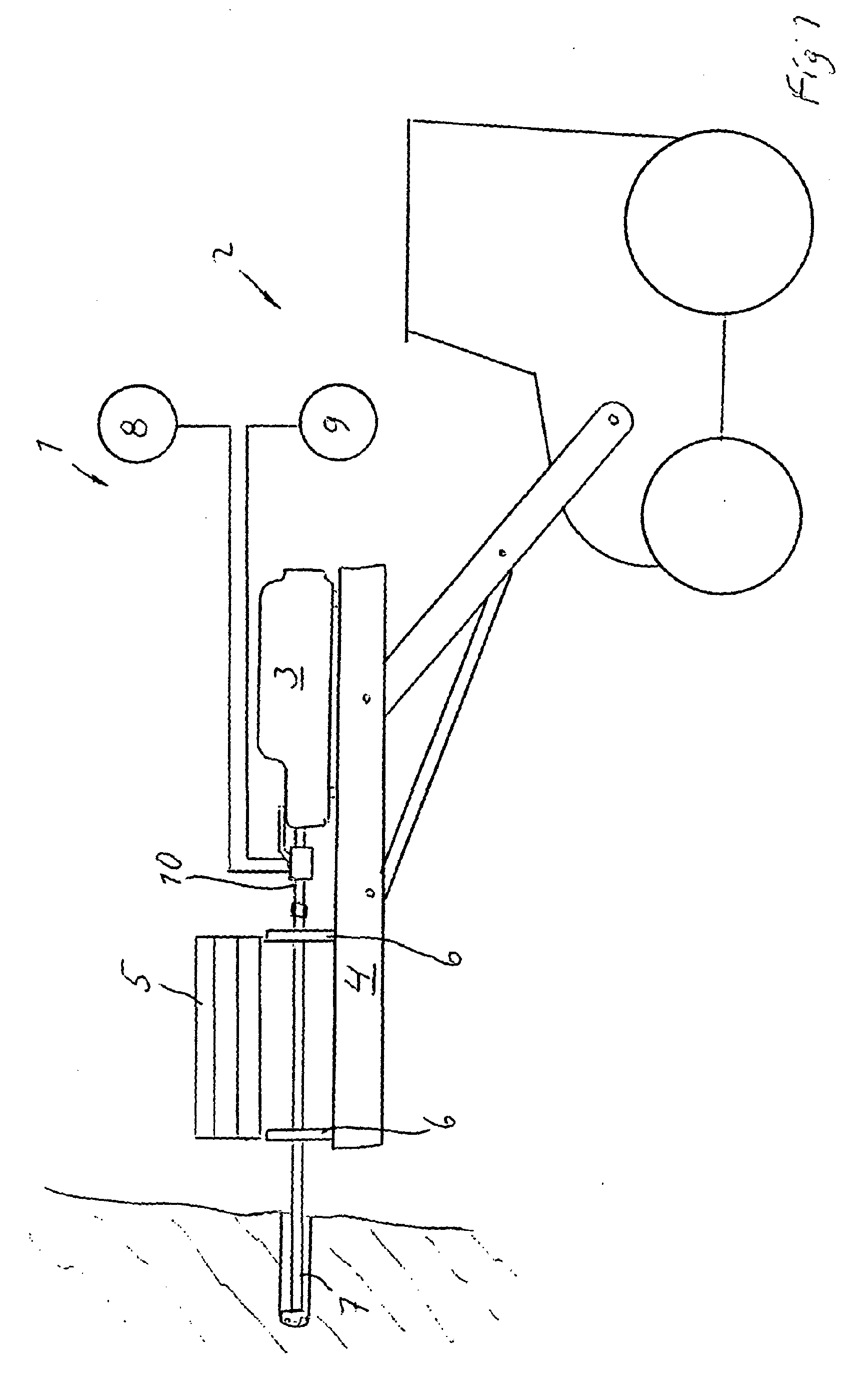
Fig. 1 diagrammatically shows a device for automatized rock bolting including a drill
rig, and
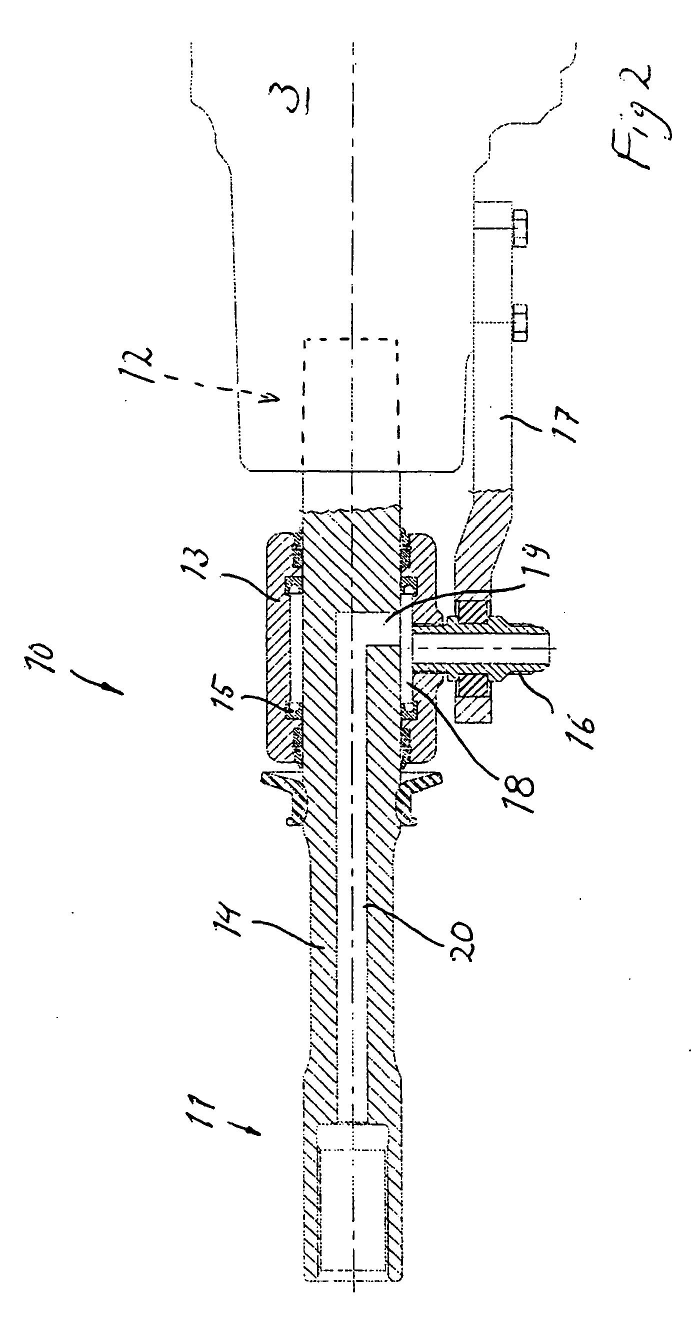
Fig. 2 shows in greater detail a device for rock bolting according to the invention.
DESCRIPTION OF EMBODIMENT
[0015] A device 1 for automatized rock bolting with self drilling rock bolts includes a
drilling rig 2 having means for supporting a conventional drilling machine 3 which
is reciprocally movable on a longitudinal guide 4. A storage facility for rock bolts
and/or jointing rods for rock bolts is indicated with 5.
[0016] Along a guide 4 there are provided drills supports 6 for supporting a self drilling
rock bolt 7 with possible thread joined jointing rod in the drilling process.
[0017] The storage facility and the drill supports functions in general like ones that are
provided in conventional devices for automatized drilling and are therefore not described
more detailed here.
[0018] A source for flushing medium 8 is over conduits and an adapter device 10 arranged
to communicate with the self drilling rock bolt 7 for flushing during drilling a bore
hole for the rock bolt at a determined location into the rock structure to be reinforced.
[0019] A source for bolt grouting medium 9 for injecting cement or corresponding grouting
medium is also arranged to communicate with the rock bolt 7 over the adapter device
10. This can be accomplished by feeding this medium continuously during the drilling
process as flushing medium/injection medium or after termination of the drilling process
as conventional grouting medium.
[0020] The device for rock bolting 10 is shown in more detail on Fig. 2 as an adapter device
10, whereby is evident that the device includes a longitudinal adapter element 14
having a distal end 11 for connection to a self drilling rock bolt and a proximal
end 12 comprising an integral connection portion of the adapter element 14 for cooperation
with a conventional rock drilling machine 3.
[0021] According to the invention is hereby intended that the adapter element including
the connection portion is comprised of one single integral element which is manufactured
in one piece. This results in that this element withstands the loads that the shock
wave causes in percussion drilling. Hereby a real possibility of automatizing the
bolting process is provided.
[0022] A swivel sleeve 13 is arranged surrounding a portion of the adapter element 14, rotationally
fixed, fastened to the drilling machine 3 over a rotation preventing arm 17. This
element is on the one hand fastened to the drilling machine 3 and provides on the
other hand means in form of a ring-shaped end portion for cooperation with a connection
nipple 16 extending radially from the swivel sleeve 13. The swivel sleeve is thereby
arranged non-rotational with respect of the drilling machine.
[0023] The connection nipple 16 is intended to be connected to either of the sources 8 or
9 in Fig. 1 for flushing and injection of grouting medium respectively. As an alternative,
there could of course be arranged two connection nipples, one for communication with
each source.
[0024] The swivel sleeve 13 provides sealings 15 on each side of an annular space 18, surrounding
a portion of the adapter element 14, wherein a radial channel 19 (can be more than
one) debouches. The channel 19 connects the space 18 with an axial channel 20 which
debouches in the inside of a recessed portion for a self drilling rock bolt at the
distal end of the adapter element 14. This way medias from the sources 8 and 9 in
Fig. 1 will be transmitted to a rock bolt which is inserted into the recessed portion.
[0025] A method for rock bolting according to the invention is as follows:
STEP 1
[0026] In a recessed portion in an adapter device which is inserted into a drilling machine
there is connected a self drilling rock bolt to be driven-in and anchored.
STEP 2
[0027] The drilling step proceeds as usual with the difference that flushing of the area
of a drill bit of the self drilling rock bolt is not flushed over the drilling machine
itself but over the adapter device, which is either connected to a flushing medium
source or to a light flowing cement which simultaneously flushes and grouts.
STEP 3
[0028] After having driven-in the self drilling rock bolt passed a front drill support on
the drilling machine guide, the rotational direction of the drilling machine 3 is
reversed for loosening the thread engagement between the female thread on the distal
end of the adapter element and the rock bolt. The rock bolt is now free to be used
as rock reinforcement or to be jointed with a jointing rod and be drilled-in further.
STEP 4
[0029] The drilling machine 3 is reversed in order to alternatively be in a position to
cooperate with a jointing rod if this is necessary for insertion of a sufficiently
long rock bolt, whereby after having been driven-in, cement is injected in a manner
indicated above. This injection step is also applicable in case the rock bolt was
ready to use already after step 2 and cement (or the like) has not been used for flushing.
[0030] The advantages achieved through the invention could be summarised as follows:
[0031] No loose coupling has to be handled since the rock bolt will always become unfastened
from the adapter element because of the presence of only one thread joint.
[0032] Continuous cement injection can be made during drilling.
[0033] The bolt is installed in one single operation since injection of the cement does
not require connecting of a separate pump to the bolt.
[0034] Completely mechanised/automatized installation of self drilling bolts can be realized
according to the invention and with the aid of a bolt storage facility.
1. Device for rock bolting with an adapter device (10) for connection of a drilling machine
(3) to a self drilling rock bolt (7), said adapter device including an adapter element
(14) which is sealingly surrounded by a swivel sleeve (13) that is arranged for connection
of an axial channel through the adapter device (20), which in operation cooperates
with an axial flushing channel in the rock bolt, to one external source or external
sources for flushing medium (8) and bolt grouting medium (9), wherein the adapter
element (14) at a distal end (11) includes a thread for connecting to a corresponding
thread on the rock bolt (7), whereby the adapter element (14) at a proximal end (12)
includes an integral connection portion for connection to the drilling machine (3)
characterized in
- that the adapter element including the connection portion is comprised of one single integral
element in one piece.
2. Device according to claim 1, characterized in that the thread on the adapter element is a female thread and that the thread on the rock
bolt is a male thread.
3. Device according to claim 1 or 2,
characterized in that the swivel sleeve (13) has an essentially radially extending connection nipple (16),
for flushing medium, bolt grouting medium, which is arranged for cooperation with
a rotational preventing arm (17), which is arranged to be fastened to the drilling
machine.
4. Device according to claim 1, 2 or 3, wherein it is arranged to be used in automatized
rock bolting,
characterized in that the adapter element has a length that exceeds a distance between the drilling machine
(3) in its most advanced position and a front drill support (6) for a rock bolt (7)
to be driven in.
5. Device (1) for automatized rock bolting with self drilling rock bolts and including
a drilling machine (3) which is reciprocal on a guide (4), a rock bolt storage facility
(5) for self drilling rock bolts (7), (one) external (source) sources for flushing
medium (8) and bolt grouting medium (9), bore support for a rock bolt which is in
a position to be driven in, including a device (7) for rock bolting according to any
of the claims 1 - 4.
6. Method for rock bolting with self drilling rock bolts, wherein a drilling machine
(3) drives a rock bolt during simultaneous flushing with a flushing medium and injection
with bolt grouting medium respectively over an adapter device (10), which includes
an adapter element (14) that is sealingly surrounded by a swivel sleeve (13), wherein
the adapter device (10) is threaded to the rock bolt to be driven in, wherein the
adapter element (14) is connected to the drilling machine (3) by means of an integral
connection portion at a proximal end (12), wherein the adapter device is unfastened
from its engagement with the rock bolt by rotationally reversing the drilling machine,
characterised in that the adapter element including the connection portion is comprised of one single integral
element in one piece.
1. Vorrichtung zur Gesteinsverankerung mit einer Adaptervorrichtung (10) zur Verbindung
einer Bohrmaschine (3) mit einem selbstbohrenden Gesteinsanker (7), wobei die Adaptervorrichtung
ein Adapterelement (14) beinhaltet, welches dichtend umgeben ist von einer Drehhülse
(13), die zur Verbindung eines axialen Kanals durch die Adaptervorrichtung (20), welcher
im Betrieb zusammenwirkt mit einem axialen Spülkanal im Gesteinsanker, mit einer externen
Quelle oder externen Quellen für Spülmedium (8) und Ankervergußmedium (9) angeordnet
ist, wobei das Adapterelement (14) an einem distalen Ende (11) ein Gewinde zur Verbindung
mit einem entsprechenden Gewinde auf dem Gesteinsanker (7) beinhaltet, wobei das Adapterelement
(14) an einem proximalen Ende (12) einen integrierten Verbindungsabschnitt zur Verbindung
mit der Bohrmaschine (3) beinhaltet, dadurch gekennzeichnet, dass das den Verbindungsabschnitt beinhaltende Adapterelement (14) aus einem einzelnen
integrierten Element in einem Stück besteht.
2. Vorrichtung gemäß Anspruch 1, dadurch gekennzeichnet, dass das Gewinde auf dem Adapterelement ein aufnehmendes Gewinde und dass das Gewinde
auf dem Gesteinsanker ein eingreifendes Gewinde ist.
3. Vorrichtung gemäß Anspruch 1 oder 2, dadurch gekennzeichnet, dass die Drehhülse (13) einen im wesentlichen sich radial erstreckenden Verbindungsstutzen
(16) für Spülmedium, Ankervergussmedium hat, welcher angeordnet ist für das Zusammenwirken
mit einem rotationsverhindernden Ausleger (17), welcher angeordnet ist, um an die
Bohrmaschine befestigt zu sein.
4. Vorrichtung gemäß Anspruch 1, 2 oder 3, wobei sie geeignet ist, um zur automatisierten
Gesteinsverankerung verwendet zu werden, dadurch gekennzeichnet, dass das Adapterelement eine Länge hat, die eine Distanz zwischen der Bohrmaschine (3)
in ihrer vorgerücktesten Position und einer vorderen Bohrstütze (6) für einen einzutreibenden
Gesteinsanker (7), übersteigt.
5. Vorrichtung (1) zur automatisierten Gesteinsverankerung mit selbstbohrenden Gesteinsankern
und beinhaltend eine Bohrmaschine (3), die auf einer Führung (4) hin und her bewegbar
ist, eine Gesteinsankerlagereinrichtung (5) für selbstbohrende Gesteinsanker (7),
(eine) externe (Quelle) Quellen für Spülmedium (8) und Ankervergußmedium (9), Bohrstützen
für einen Gesteinsanker, der in einer einzutreibenden Position ist, beinhaltend eine
Vorrichtung (7) zur Gesteinsverankerung gemäß irgendeinem der Ansprüche 1 bis 4.
6. Verfahren zur Gesteinsverankerung mit selbstbohrenden Gesteinsankern, worin eine Bohrmaschine
(3) einen Gesteinsanker antreibt, während dem jeweils gleichzeitigen Spülen mit einem
Spülmedium und Injizieren mit Ankervergußmedium über eine Adaptervorrichtung (10),
welche ein Adapterelement (14) beinhaltet, das dichtend umgeben ist von einer Drehhülse
(13), wobei die Adaptervorrichtung (10) mit dem einzutreibenden Gesteinsanker verschraubt
ist, wobei das Adapterelement (14) mit der Bohrmaschine (3) mittels eines integrierten
Verbindungsabschnittes an einem proximalen Ende (12) verbunden ist, wobei die Adaptervorrichtung
von ihrer Bindung mit dem Gesteinsanker durch Umkehrung der Drehrichtung der Bohrmaschine
gelöst wird, dadurch gekennzeichnet, dass das Adapterelement beinhaltend den Verbindungsabschnitt aus einem einzelnen integrierten
Element in einem Stück besteht.
1. Dispositif de mise en place de boulons d'ancrage doté d'un dispositif (10) d'adaptateur
permettant de connecter une perforatrice (3) avec un boulon autoforeur (7), ledit
dispositif d'adaptateur incluant un élément (14) d'adaptateur qui est entouré de manière
étanche par un manchon (13) de tourillon agencé pour connexion d'un canal axial via
le dispositif (20) d'adaptateur, lequel, en fonctionnement, coopère avec un canal
axial d'injection réalisé dans le boulon d'ancrage, avec une ou des sources extérieures
d'un milieu (8) de nettoyage et d'un milieu (9) de scellement de boulons, dans lequel
l'élément (14) d'adaptateur situé à une extrémité distale (11) inclut un filetage
pour connexion avec un filetage correspondant réalisé sur le boulon d'ancrage (7),
grâce à quoi l'élément (14) d'adaptateur qui se trouve à une extrémité proximale (12)
inclut une partie de connexion intégrée pour connexion avec la perforatrice (3),
caractérisé en ce que l'élément d'adaptateur incluant la partie de connexion est constitué d'un unique
élément intégré réalisé d'une seule pièce.
2. Dispositif selon la revendication 1, caractérisé en ce que le filetage réalisé sur l'élément d'adaptateur est un filetage femelle, et en ce que le filetage réalisé sur le boulon d'ancrage est un filetage mâle.
3. Dispositif selon la revendication 1 ou 2, caractérisé en ce que le manchon (13) de tourillon comporte un embout (16) de raccordement s'étendant essentiellement
radialement, prévu pour un milieu de nettoyage, un milieu de scellement de boulons,
qui est agencé pour coopération avec un bras (17) empêchant une rotation, qui est
agencé pour fixation à la perforatrice.
4. Dispositif selon la revendication 1, 2 ou 3, étant agencé pour utilisation lors d'une
mise en place automatisée de boulons d'ancrage, caractérisé en ce que l'élément d'adaptateur a une longueur qui dépasse une distance entre la perforatrice
(3), dans sa position la plus avancée, et un support avant (6) de dispositif de perforation
d'un boulon d'ancrage (7) devant y être entraîné.
5. Dispositif (1) de mise en place automatisée de boulons d'ancrage doté de boulons d'ancrage
autoforeurs et incluant une perforatrice (3) qui est mobile à va-et-vient sur un guide
(4), une unité (5) de stockage de boulons d'ancrage destinée à des boulons d'ancrage
autoforeurs (7), une ou des sources extérieures destinées à un milieu (8) de nettoyage
et à un milieu (9) de scellement de boulons, un support de dispositif de perforation
destiné à un boulon d'ancrage qui se trouve dans une position pour y être entraîné,
incluant un dispositif (1) de mise en place de boulons d'ancrage selon l'une quelconque
des revendications 1 à 4.
6. Procédé pour mise en place de boulons d'ancrage doté de boulons d'ancrage autoforeurs,
dans lequel une perforatrice (3) entraîne un boulon d'ancrage pendant, simultanément,
un nettoyage avec un milieu de nettoyage et une injection d'un milieu de scellement
de boulons effectués respectivement sur un dispositif (10) d'adaptateur, qui inclut
un élément (14) d'adaptateur qui est entouré de manière étanche par un manchon (13)
de tourillon, dans lequel le dispositif (10) d'adaptateur est vissé sur le boulon
d'ancrage devant y être entraîné, dans lequel l'élément (14) d'adaptateur est relié
à la perforatrice (3) au moyen d'une partie intégrée de connexion située à une extrémité
proximale (12), dans lequel le dispositif d'adaptateur est désaccouplé de son engagement
avec le boulon d'ancrage par inversion de rotation de la perforatrice, caractérisé en ce que l'élément d'adaptateur incluant la partie de connexion est constitué d'un unique
élément intégré réalisé d'une seule pièce.
REFERENCES CITED IN THE DESCRIPTION
This list of references cited by the applicant is for the reader's convenience only.
It does not form part of the European patent document. Even though great care has
been taken in compiling the references, errors or omissions cannot be excluded and
the EPO disclaims all liability in this regard.
Patent documents cited in the description