| (19) |
 |
|
(11) |
EP 1 808 660 A2 |
| (12) |
EUROPEAN PATENT APPLICATION |
| (43) |
Date of publication: |
|
18.07.2007 Bulletin 2007/29 |
| (22) |
Date of filing: 03.01.2007 |
|
| (51) |
International Patent Classification (IPC):
|
|
| (84) |
Designated Contracting States: |
|
AT BE BG CH CY CZ DE DK EE ES FI FR GB GR HU IE IS IT LI LT LU LV MC NL PL PT RO SE
SI SK TR |
|
Designated Extension States: |
|
AL BA HR MK YU |
| (30) |
Priority: |
16.01.2006 IT VA20060003 U
|
| (71) |
Applicant: WHIRLPOOL CORPORATION |
|
Benton Harbor
Michigan 49022 (US) |
|
| (72) |
Inventors: |
|
- Pieragostini, Fabrizio
21025, Comerio (IT)
- Giangiulio, Andrea
21025, Comerio (IT)
|
| (74) |
Representative: Guerci, Alessandro |
|
Whirlpool Europe S.r.l.
Patent Department
Viale G. Borghi 27
21025 Comerio (VA)
21025 Comerio (VA) (IT) |
|
| |
|
| (54) |
Device for installing a thermal sensor, particularly for evaporators of refrigerators
or freezers |
(57) A device for installing a thermal sensor (12) on a pipe (T'), particularly on a tubular
pipe of an evaporator or condenser of refrigerators and the like, has a sensor provided
with a snap-on portion for coupling to said pipe. The device further comprises a frame-like
structure (14) capable of acting in response to the sensor in order to ensure correct
positioning on the pipe, said structure comprising a snap-on portion (14a) for quick
coupling to a different portion of the pipe.
|
|
[0001] The present invention concerns a device for installing a thermal sensor on a pipe,
particularly on a tubular pipe of an evaporator or condenser of household appliances
such as refrigerators, air conditioners or the like.
[0002] It is well known, in the field of household appliances (with particular reference
to refrigerators or freezers provided with a tubular evaporator) that it is necessary
to determine precisely and accurately the temperature of the evaporator with the aim
of supplying essential data to the control system of the household appliance. This
is true both where electromechanical thermal sensors, for example thermostats, are
used and where more sophisticated temperature sensors, interfaced with the electronic
control system of the household appliance is used. Any sub-optimal positioning of
the sensor on the evaporator can give rise to disadvantages both as concerns the correct
control of disconnecting and reconnecting the compressor at the desired temperatures,
and as concerns control of the air-circulation fan (particularly in the case of so-called
"no-frost" refrigerators) or the defrosting resistor of the evaporator. This incorrect
positioning can take place because of the system for quick-coupling the sensor to
a portion of evaporator pipe, since said coupling system (for example of the semicircular
clip type) does not guarantee a predetermined angular position in that the sensor
can rotate on the pipe. Furthermore, slight differences of angular positioning of
the sensor on the pipe can give rise to malfunctions with the consequent need to resort
to the repair service, with the related costs and disadvantages.
[0003] The aim of the present invention is to provide a device of the type specified at
the beginning of the description, making it possible to overcome the aforesaid disadvantages,
always ensuring correct positioning of the sensor on the evaporator. This aim is achieved
through the characteristics specified in the attached claims.
[0004] According to the invention, the correct positioning of the sensor is guaranteed by
an auxiliary installation device that comprises a peripheral frame-like structure
capable of acting in response to the sensor position, said structure also comprising,
like the sensor, a snap-on portion for quick coupling to a different portion of the
pipe, and preferably to a portion of the pipe that is substantially parallel to the
portion of pipe on which the sensor is mounted.
[0005] Further advantages and characteristics of a device according to the invention will
be apparent from the following detailed description, provided purely by way of non-restrictive
example, with reference to the attached drawings in which:
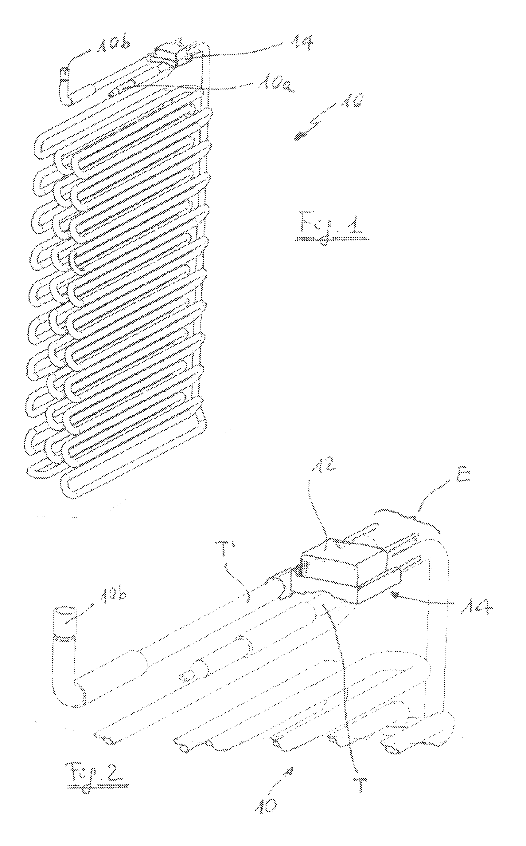
- Figure 1 is a perspective view of an evaporator provided with the device according
to the invention;
- Figure 2 is a larger-scale detail from Figure 1;
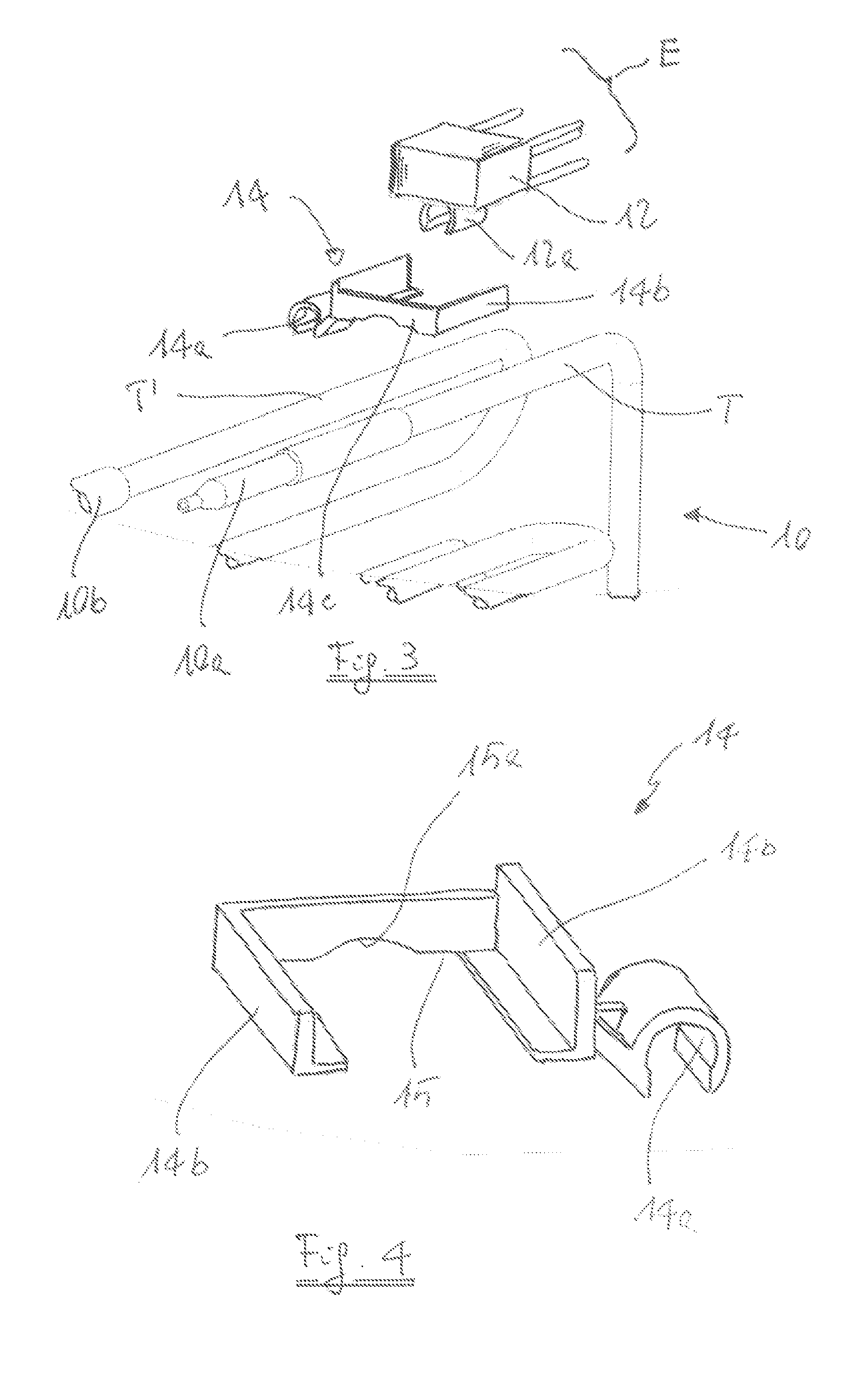
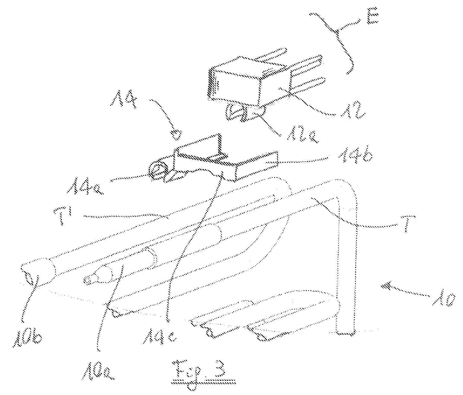
- Figure 3 is an exploded perspective view of the detail from Figure 2; and
- Figure 4 is a perspective view of the device according to the invention.
[0006] With reference to the drawings, the number 10 denotes as a whole an evaporator for
a no-frost type refrigerator/freezer. The evaporator 10 comprises an inlet connector
10a for the cooling fluid downstream from the discharge of a compressor (not illustrated)
and an outlet connector 10b upstream from the intake of the compressor. Adjacent to
the inlet connector 10a, on the tubing T of the evaporator 10, a resilient semicircular
appendix 12a of a thermolimiter device 12 of a type known
per se is mounted by snapping on.
[0007] According to the invention, on a portion of piping T' adjacent to the outlet connector
10b, an installation device 14 shaped like a U-shaped frame, is mounted by snapping
on. The device 14 comprises a resilient semicircular appendix 14a arranged laterally
and similar in shape to the appendix 12a of the thermolimiter 12. The device 14 further
comprises two arms 14b with an L-shaped cross-section and a central connector 14c
having an edge 15 on which a circular incision 15a is made.
[0008] As clearly illustrated in Figures 2 and 3, the installation device 14 is mounted,
by means of its resilient lateral appendix 14a, on the piping T' of the evaporator
10 in such a way that its circular incision 15a is in contact with the parallel piping
T of the evaporator 10. Subsequently, the thermolimiter 12, provided with terminals
E for connection to the electricity supply, the defrosting resistor, the fan and the
control circuit of the refrigerator, is snapped on to the piping T in such way that
its edges abut upon the two arms 14b of the device 14, preventing either the rotation
of the thermolimiter on the piping T or the rotation of the installation device 14
on the parallel piping T'. The shape of the circular incision 15a is such as to ensure
that the arms 14b of the device 14 are positioned in contact with the lower face of
the thermolimiter 12. In contrast with what happens in the known type of refrigerators,
an unambiguous position of the thermolimiter 12 is therefore defined, which is highly
advantageous for its normal operation. Moreover the particular shape of the device
14 makes it possible to avoid any reduction in heat exchange between piping and thermolimiter.
1. Device for installing a thermal sensor (12) on a pipe (T), particularly on a tubular
pipe (T) of an evaporator (10) or condenser of refrigerators and the like, in which
the sensor (12) is provided with a snap-on portion (12a) for coupling to said pipe
(T), characterised by the fact that it comprises a frame-like structure (14) capable of acting in response
(14b) to the sensor (14) in order to ensure correct positioning on the pipe (T), said
structure comprising a portion (14a) for quick-coupling to a different portion of
the pipe (T'),
2. Device according to Claim 1, characterised by the fact that the frame-like structure (14, 14b) is intended, when the sensor (12)
is in the operating configuration, to come into contact with a peripheral portion
of the sensor (12) without preventing direct contact between said sensor (12) and
the pipe (T).
3. Device according to Claim 2, characterised by the fact that the frame-like structure (14) comprises a snap-on portion (14a) for
coupling to a pipe (T') parallel to the pipe (T) on which the sensor (12) is intended
to be installed.
4. Device according to Claim 3, characterised by the fact that the frame-like structure (14) is substantially U-shaped in order to
allow easy insertion of the sensor (12).
5. Device according to Claim 4, characterised by the fact that the snap-on portion (14a) for quick coupling to the pipe (T') is defined
by a lateral appendix (14a) of the frame-like structure (14).