| (19) |
 |
|
(11) |
EP 1 021 788 B1 |
| (12) |
EUROPEAN PATENT SPECIFICATION |
| (45) |
Mention of the grant of the patent: |
|
22.07.2009 Bulletin 2009/30 |
| (22) |
Date of filing: 14.11.1997 |
|
| (51) |
International Patent Classification (IPC):
|
| (86) |
International application number: |
|
PCT/US1997/021790 |
| (87) |
International publication number: |
|
WO 1998/021697 (22.05.1998 Gazette 1998/21) |
|
| (54) |
UNIVERSAL BANK NOTE DENOMINATOR AND VALIDATOR
UNIVERSELLER BANKNOTEN-WERT-FESTSTELLER UND EVALUIERER
DISPOSITIF UNIVERSEL D'ATTRIBUTION DE VALEUR NOMINALE A DES BILLETS DE BANQUES ET
DE VALIDATION DESDITS BILLETS
|
| (84) |
Designated Contracting States: |
|
DE ES FR GB IT |
| (30) |
Priority: |
15.11.1996 US 749260
|
| (43) |
Date of publication of application: |
|
26.07.2000 Bulletin 2000/30 |
| (73) |
Proprietors: |
|
- Diebold SST Holding Company, Inc.
North Canton, Ohio 44720 (US)
- Diebold Holding Company, Inc.
North Canton, Ohio 44720 (US)
|
|
| (72) |
Inventor: |
|
- LASKOWSKI, Edward, L.
Seven Hills, OH 44131 (US)
|
| (74) |
Representative: Boden, Keith McMurray et al |
|
D Young & Co
120 Holborn
London EC1N 2DY
London EC1N 2DY (GB) |
| (56) |
References cited: :
WO-A-93/23824
US-A- 4 255 057
US-A- 4 723 072
US-A- 5 363 949
|
US-A- 3 922 557
US-A- 4 319 137
US-A- 4 930 866
US-A- 5 367 577
|
|
| |
|
|
|
|
| |
|
| Note: Within nine months from the publication of the mention of the grant of the European
patent, any person may give notice to the European Patent Office of opposition to
the European patent
granted. Notice of opposition shall be filed in a written reasoned statement. It shall
not be deemed to
have been filed until the opposition fee has been paid. (Art. 99(1) European Patent
Convention).
|
TECHNICAL FIELD
[0001] This invention relates to devices for identifying the type and validity of documents.
Specifically this invention relates to a device for identifying the denomination and
authenticity of currency notes.
BACKGROUND ART
[0002] Numerous devices have been previously developed for identifying documents and determining
their authenticity. Document
US 3922557,
US 5 367 577 and
WO 93/23824 describe examples of such devices. Likewise, devices have been previously developed
for determining the denomination and authenticity of bank and currency notes. Such
devices commonly test different properties of a presented note and based on the properties
sensed, give an indication of the denomination and/or authenticity of the presented
note. All such prior art devices have limitations.
[0003] Many prior art devices require precise alignment of the note during sensing of its
properties. This requires the device to include a mechanism to align the notes and
often limits the speed at which the notes can be processed. In addition, some devices
require that presented notes be oriented in a particular way as they are sensed. This
limits their usefulness as notes are often not presented in a uniform orientation.
[0004] Many prior art devices for determining note denomination and validity are capable
of processing only a small number of note types. This presents drawbacks as other
note types cannot be processed. Such prior art devices are also generally made to
be used with only one type of currency such as the currency of a particular country.
Often it is difficult or impossible to adapt such devices to handle currencies of
countries which have different physical properties. Furthermore, it may be difficult
to adapt such devices to a new printing series of notes within the same country.
[0005] Many prior art devices are also amenable to compromise by counterfeit notes. It is
becoming easier to produce highly accurate counterfeit reproductions of currency.
By mimicking the properties of a note that are tested by prior art currency denominators
and validaters, it is often possible to have counterfeit notes accepted.
[0006] To minimize the risk of acceptance of counterfeits, the range of the acceptance criteria
in prior art devices can often be set more closely. However, currency notes in circulation
change properties through use fairly quickly. Notes in circulation may change their
properties through handling and wear. Notes may become dirty or marked with ink or
other substances. Notes may also lose their color due to having been mistakenly washed
with clothing or exposed to water or sunlight. Prior art currency denominators and
validaters may reject valid notes which exhibit such properties when the criteria
for acceptance is set too tightly.
[0007] Note denominators and validaters currently available may also be difficult to program
and calibrate. Such devices, particularly if they must have the capability of handling
more than one type of note, may require significant effort to set up and program.
In addition, such devices may require initial calibration and frequent periodic recalibration
and adjustment to maintain a suitable level of accuracy.
[0008] Prior art note denominators and validaters, particularly those having greater capabilities,
often occupy significant physical space. This limits where they may be installed.
In addition, such devices also often have a relatively high cost which limits their
suitability for particular uses and applications.
[0009] Thus, there exists a need for a currency note denominator and validater which is
more accurate, has greater capabilities, is faster, smaller in size, and lower in
cost.
DISCLOSURE OF INVENTION
[0010] Aspects of the invention are defined in the accompanying claims.
[0011] According to an embodiment of the invention, there can be provided an apparatus that
indicates the identity of a note.
[0012] According to an embodiment of the invention, there can be provided an apparatus that
indicates the identity of a note, that operates rapidly.
[0013] According to an embodiment of the invention, there can be provided an apparatus that
indicates the identity of a note, that does not require that the note have a particular
alignment or orientation.
[0014] According to an embodiment of the invention, there can be provided an apparatus that
indicates the identity of a note, that identifies notes exhibiting a variety of wear
and aging conditions.
[0015] According to an embodiment of the invention, there can be provided an apparatus that
indicates the identity of a note, that is capable of handling a wide variety of sizes
and types of currency notes.
[0016] According to an embodiment of the invention, there can be provided an apparatus that
indicates the identity of a note, that may be readily set up for operation.
[0017] According to an embodiment of the invention, there can be provided an apparatus that
indicates the identity of a note, that is compact in size.
[0018] According to an embodiment of the invention, there can be provided an apparatus that
indicates the identity of a note, that is economical to use and manufacture.
[0019] According to an embodiment of the invention, there can be provided an apparatus that
indicates the identity of a note, that is reliable.
[0020] According to an embodiment of the invention, there can be provided a method for identifying
a type associated with a note,
[0021] According to an embodiment of the invention, there can be provided a method for identifying
a type associated with a note, that is accurate.
[0022] According to an embodiment of the invention, there can be provided a method for identifying
a note, that is capable of identifying notes having various wear and aging conditions.
[0023] According to an embodiment of the invention, there can be provided a method for identifying
a note, which can be used with a wide variety of notes of various orientations.
[0024] According to an embodiment of the invention, there can be provided a method for identifying
notes, that can be performed rapidly by a control circuit.
[0025] According to an embodiment of the invention, there can be provided a method for identifying
a note, that can be used to identify notes that are not consistently aligned or in
a particular orientation.
[0026] According to an embodiment of the invention, there can be provided an apparatus and
method for providing an indication of the type of a note. The apparatus can be used
for providing signals indicative of a denomination of a currency note. This apparatus
may also provide an indication of note orientation and/or note authenticity.
[0027] An embodiment of the invention can be used in connection with a transport for moving
notes. A plurality of spaced spot sensing assemblies can be disposed transversely
to a direction of note movement in the transport.
[0028] Three spot sensing assemblies can be used, although other embodiments of the invention
may include other numbers of such assemblies.
[0029] Each assembly can include a radiation source which comprises a plurality of emitters.
Each emitter can generate radiation at a different wavelength. According to an embodiment
of the invention four emitters are used. The emitters can generally span the range
of visible light as well as infrared. According to an embodiment of the invention
the emitters include in each assembly red, green, blue and infrared emitters. Each
of the emitters in an assembly can be aimed to illuminate a spot on a passing note.
[0030] Each spot sensing assembly includes a first detector. The first detector can be positioned
on a first side of the note as it passes in the transport. The first detector can
be positioned in centered relation with respect to the emitters. The first detector
can sense radiation from the emitters reflected from the test spots on the note.
[0031] Each assembly also includes a second detector. The second detector is positioned
on a second side of the note opposite the first detector. The second detector can
detect radiation from each emitter that passes through the test spots on the note.
[0032] The apparatus inlcudes a circuit in operative connection with a data store. The circuit
can be operable to actuate each of the emitters in each spot sensing assembly in a
sequence. In accordance with one form of the invention the sequence all of the emitters
of the same type produce radiation simultaneously while all of the other types of
emitters are off. Alternatively, the sequence may provide for emitters in the spot
sensing assemblies to be turned on at different times. However, in one embodiment,
only one emitter in each spot sensing assembly is , active at any one time while the
sensors are being read. The emitters can be activated in the sequence continuously.
[0033] The emitters can be sequenced numerous times as the note in the transport passes
adjacent to the spot sensing assemblies. As a result, three sets of test spots can
be arranged in a line are sensed on each passing note.
[0034] For each test spot, the first detector which senses reflection can produce a first
signal responsive to each emitter. Each first signal can be representative of the
amount of radiation reflected from the test spot from a corresponding emitter. Likewise,
the second detector can produce second signals responsive to the amount of light transmitted
through the test spot on the note from each emitter.
[0035] The circuit can be operative to receive the first and second signals from the first
and second detectors respectively, and to generate reflectance and transmission values
in response thereto. For each test spot four reflectance and four transmission values
can be generated. Likewise, for each row of three test spots which are checked on
the note simultaneously by the three spot sensing assemblies, twelve reflectance values
and twelve, transmission values can be generated. In accordance with an embodiment
of the invention generally about 29 rows of test spots can be sensed as the note moves
past the spot sensing assemblies. This can result in the circuit generating about
348 reflective values and 348 transmission values per note.
[0036] The values in the data store can correspond to reflectance and transmission values
for a number of note types in various orientations and spatial positions. The circuit
can be operative to generate stored value sets from the values in the data store.
Stored value sets can be generated based on the angle of skew of the note, which is
detected as, it passes the sensing assemblies. Numerous stored value sets can be generated
by the circuit, each corresponding to a particular note, denomination, note orientation,
and note position.
[0037] The circuit can be operative to calculate values representative of the levels of
correlation between the sensed value set of reflectance and transmission values for
the note, and each of the stored value sets. By comparing the level of correlation
between the sensed value set and the stored value sets, a highest correlation value
can be determined. The highest level of correlation will be with a stored value set
that corresponds to the particular denomination and orientation of the note which
passed through the transport to produce the sensed value set. The circuit can be operative
to generate a signal indicative of the note type it identifies.
[0038] In accordance with an embodiment of the invention the circuit can be operative to
compare the highest correlation value with a set threshold value. Even worn notes
and those that have been subject to abuse exhibit a relatively high level of correlation
with a stored value set for the correct note type. If however, the level of correlation
is not above the set threshold, then the note may not be identifiable, or it may he
a counterfeit or it may be identified and determined to be unfit for reuse. The circuit
can generate signals indicative of these conditions.
BRIER DESCRIPTION OF THE DRAWINGS
[0039]
Figure 1 is a schematic of a preferred embodiment of the apparatus for identifying
notes of the present invention.
Figure 2 is an isometric schematic view of three spot sensing assemblies sensing test
spots on a moving note.
Figure 3 is a schematic view of a spot sensing assembly.
Figure 4 is a schematic representation demonstrating how a set of sensed data values
from a test note is correlated with previously stored value sets for a plurality of
note denominations and orientations in the operation of the apparatus of the present
invention.
Figure 5 is a schematic representation demonstrating the calculation of a value representative
of a level of correlation between a set of sensed data values and a stored data value
set for a particular note type.
Figure 6 is a schematic representation of data sensed from three spot sensing assemblies
and the calculation of a value representative of a level of correlation between the
sensed value set and a stored value set.
Figure 7 is a schematic representation of values stored in a data store of the preferred
embodiment of the invention, and how this data is correlated with a sensed value set.
Figure 8 is a schematic view of a note passing through the apparatus of the present
invention in a skewed condition.
Figure 9 is a schematic representation of data generated by the circuit of the invention
responsive to signals from the spot sensing assemblies for the skewed note shown in
Figure 8.
Figure 10 is a tabular representation of the data shown in Figure 9 shifted for purposes
of calculating a value representative of a level of correlation.
Figure 11 is a schematic representation demonstrating how sensed value data from a
skewed note is correlated with data stored in the data store of the invention.
Figure 12 is a schematic representation showing the steps in the correlation sequence
carried out in the preferred embodiment of the present invention.
Figure 13 is a schematic view of the control circuit of the preferred embodiment of
the present invention.
Figure 14 is a graphical representation of reflectance signals obtained from transversely
disposed spot sensing assemblies for a skewed note, which signals are used by the
control circuit to determine an angle of skew.
Figure 15 is a schematic view of a skewed note and three transversely disposed spot
sensing assemblies which correspond to the data graphically shown in Figure 14.
BEST MODES FOR CARRYING OUT INVENTION
[0040] Referring now to the drawings and particularly to Figure 1, there is shown therein
a preferred embodiment of an apparatus of the present invention generally indicated
10. The apparatus includes a note transport 12. Transport 12 is preferably a belt-type
transport that moves sheets such as currency notes one at a time from an entry end
14 to an exit end 16. Sheets such as notes move on the transport 12 in a note direction
indicated by Arrow A.
[0041] The apparatus of the present invention also includes a plurality of spot sensing
assemblies 18. The preferred form of the invention includes three spot sensing assemblies
which are spaced from one another in a direction transverse of the note direction
of note movement (see Figure 3).
[0042] Each of the spot sensing assemblies includes a reflectance detector, schematically
indicated 20. Each spot sensing assembly 18 also includes a transmission detector
schematically indicated 22. As indicated in Figure 1 the reflectance detector 20 is
in operative connection with, and outputs first signals to, a control circuit schematically
indicated 24. The transmission detectors 22 are also in operative connection with
the control circuit 24, and the transmission detectors output second signals thereto.
Control circuit 24 is also in operative connection with a data store schematically
indicated 26 which holds stored values in a manner later explained.
[0043] The apparatus of the present invention may in certain embodiments also include auxiliary
validation sensors schematically indicated 28. The auxiliary sensors 28 preferably
detect properties of passing notes that are not detected by the spot sensing assemblies.
These auxiliary sensors may include, for example, magnetic type sensors or sensors
for sensing identification strips on passing notes or sheets. The auxiliary sensors
28 do not form part of the present invention and are not further discussed herein.
It will be understood however, that many types of auxiliary sensors may be used in
connection with the present invention and the signals output by such sensors are processed
and analyzed in the control circuit 24 through appropriate electronic components.
[0044] The spot sensing assemblies 18 are shown in greater detail in Figures 2 and 3. Each
spot sensing assembly includes a reflectance detector 20, which in the preferred form
of the invention includes a photocell. The reflectance detectors 20 are positioned
on a first side of a passing note 30 which is shown in phantom in Figure 2. The transport
12 moves note 30 past the spot sensing assemblies.
[0045] Each spot sensing assembly 18 includes four emitters 32. The emitters 32 are positioned
generally adjacent to, and in surrounding relation of, each reflectance detector 20.
Each spot sensing assembly includes emitters with wavelengths which generally span
the visible range of light and infrared. In the described embodiment each spot sensing
assembly includes a blue emitter, a green emitter, a red emitter, and an infrared
emitter. In the preferred form of the invention, the emitters are light emitting diodes
(LEDs) which are selectively operable to produce generally monochromatic light at
a particular wavelength. In other embodiments of the invention other types and wavelengths
of emitters may be used.
[0046] Each emitter 32 in a spot sensing assembly is oriented so as to direct and focus
radiation onto a test spot schematically indicated 34, which is shown on the adjacent
surface of a passing note. In the preferred form of the invention, because there are
three spot sensing assemblies, properties of the note are sampled simultaneously at
three test spots 34 which are transversely spaced across the bill. As best shown in
Figure 3, radiation from the emitters 32 is reflected from each test spot 34 to the
reflectance sensor 20 of the spot sensing assembly. The reflected light is passed
through a lens 36 adjacent to each reflectance detector to further focus the reflected
light thereon.
[0047] Radiation from the emitters 32 also passes through each test spot on the test note.
The transmitted radiation passes to the transmission detector 22 of each of the spot
sensing assemblies 18. In the preferred form of the invention each of the transmission
detectors 22 includes a photocell. As a result, when reflectance detector 20 senses
radiation from one of the emitters reflected from the test note, transmission detector
22 simultaneously senses radiation transmitted through the test note from the same
emitter.
[0048] In the preferred form of the invention the control circuit 24 is operable to selectively
actuate each of the emitters 32. The control circuit actuates each type emitter in
each spot sensing assembly individually, so that only one emitter in a spot sensing
assembly is producing radiation at any time.
[0049] In one embodiment, the control circuit 24 is operative to activate the same type
emitter in each of the spot sensing assemblies 18 simultaneously. For example, all
the blue emitters in each of the spot sensing assemblies are activated to produce
radiation at the same time. Thereafter, all the blue emitters go off and all the green
emitters in each of the spot sensing assemblies come on. Thereafter, the green emitters
go off and the red emitters come on. When the red emitters go off the infrared emitters
come on. The infrared emitters go off and the sequence repeats. Alternatively, the
emitters may be activated in a "marquee" style so that the particular type emitter
in each assembly is on for a time before it is read, and emitters of the same type
are read at different times. This approach has the advantage that it enables the emitters
to stabilize before being read by the controller. Of course, the sequence of emitters
may be different in other embodiments.
[0050] The emitters radiate individually and in sequence rapidly such that each emitter
comes on one time for each test spot 34. The test spots preferably are discrete and
each of the emitters direct light onto generally the same spot on the note during
one sequence despite the fact that the note is moving.
[0051] As those skilled in the art will appreciate from the foregoing description, each
reflectance detector 20 produces four first signals for each test spot 34. The four
first signals are produced responsive to radiation from the blue, green, red, and
infrared emitters respectively. Similarly, each transmission detector 22 produces
four second signals for each test spot 34. There is one second signal for the radiation
transmitted through the test spot from each of the four emitters in the spot sensing
assembly.
[0052] The control circuit 24 receives each of these first signals and is operative to generate
a reflectance value responsive to each signal representative of the magnitude of light
reflected by the note 30 from each of the emitters. Likewise, the control circuit
24 is operative to generate transmission values responsive to each of the four second
signals from transmission detector 22. Each of the transmission values are representative
of transmitted light through the test spot from each emitter. Because there are three
spot sensing assemblies 18 spaced transversely across the note, the first circuit
is operative to generate 12 reflectance values and 12 transmission values for each
row of 3 test spots 34 on the note.
[0053] In the preferred form of the invention, the control circuit 24 is operative to actuate
the emitters in the spot sensing assemblies very rapidly. This is done so the test
spots-are maintained discrete and compact. A number of test spots are preferably sensed
as a note moves past the three spot sensing assemblies 18 in the transport. In the
preferred form of the invention, the spot sensing assemblies are actuated so that
each spot sensing assembly senses about 29 test spots on a standard U.S. currency
note. This means that generally (29 x 3 = 87) test spots are sensed on the average
note. Because 4 transmission and 4 reflectance values are generated per test spot
(87 x 8 = 696), about 696 data values per note are gathered.
[0054] The transport 12 is preferably moved in such a speed that 15 standard U.S. currency
notes per second are moved past the spot sensing assemblies. Of course, in other embodiments
different numbers of test spots, data values and note speeds may be used.
[0055] A fundamental advantage of the present invention is that the emitters produce radiation
which spans the visible range of light as well as infrared. This provides signals
which test the validity of the note at a number of different wavelengths in both the
transmission and reflectance modes. This enables the gathering of much more data concerning
the note image and material properties than prior types of note denominators and validaters.
[0056] A further fundamental advantage of the present invention is that it is capable of
identifying many types of notes in different orientations. As later explained, the
preferred form of the present invention does not require that the notes be precisely
aligned either in the note direction, or transversely in the note path.
[0057] As schematically represented in Figure 4, a note which is delivered to the present
invention for identification and validation may be one of many types. The preferred
form of the invention is configured to identify 20 different denominations of notes.
Of course, other embodiments of the invention may analyze different numbers of note
denominations. However, in the preferred form of the present invention, there is no
requirement that the notes delivered be oriented a particular way. Therefore, notes
may be delivered face up, face down, as well as with the top of the note leading,
or with the bottom of the note leading. To identify the note as a particular type,
the present invention must be able to handle notes delivered in all four orientations.
[0058] In Figure 4, a sensed value set 38, representative of a set of data sensed from the
test note is shown. As previously discussed, in the preferred embodiment, this sensed
value set will generally include a set that is 24 by 29. This is because each row
of three test spots generates 24 values (12 reflectance and 12 transmission) and there
are generally 29 rows of test spots on the note.
[0059] The right side of Figure 4 shows stored value sets 40. In the preferred form of the
invention, the stored value sets are produced by the control circuit 24. The sensed
value set 38 generated from the note is compared for correlation with each of the
stored value sets 40. In Figure 4, 80 stored value sets are shown. This is representative
of the 20 note denominations multiplied by four possible orientations for each note
type.
[0060] As will be later explained in detail, in the preferred form of the invention, there
are many more than 80 stored value sets to which the sensed value set is compared.
This is because the apparatus must determine not only the particular note type ( from
among 80 possible note types and orientations), but must also determine the note type
even though the note position may be shifted either in the direction in which the
note is transported or transverse to the note direction, or may be skewed relative
to the direction of transport.
[0061] The process by which the control circuit calculates the values representation of
the level of correlation between the sensed valued set (which is representative of
the reflectance and transmission values from the sensed note) and the stored value
sets, is schematically represented in Figure 5. For purposes of the correlation calculation
carried out by the control circuit 24, the sensed value set 38 is considered to be
(x) data. The data values in the stored value set indicated 42 are considered to be
(y) data. The level of correlation is calculated in accordance with the equation:
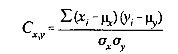
where:
- Cx,y
- is the correlation coefficient.
- xi
- is the sensed value from the sensed value set data.
- yi
- is the corresponding value in the stored value set.
- µx
- is the average of the values in the portion of the sensed value set being correlated.
- µy
- is the average of the values in the corresponding portion of the stored value set
being correlated.
- σx
- is the standard deviation of the sensed values in the portion of the sensed value
set being correlated.
- σy
- is the standard deviation in the corresponding portion of the stored value set.
[0062] As will be appreciated, the greater the correlation coefficient the higher the level
of correlation between the sensed value set and the stored value set being compared.
A high value is indicative that the stored value set corresponds to the particular
type test note that generates the data in the sensed value set.
[0063] Turning now to Figure 6 there is schematically shown a sensed value set 44 from a
note that is moved past spot sensing assemblies 18. As shown in the upper portion
of Figure 6, sensed value set 44 is a matrix that is 24 by 29. The lower portion of
Figure 6 shows a similarly sized stored value set 46 which is generated by circuit
24 from data in the data store 26 in a manner later explained.
[0064] In the preferred form of the invention each set comprising the three columns of "x"
values representing one color and mode in sensed value set 44 is checked for correlation
with corresponding values in the three columns of stored value set 46. A correlation
coefficient is calculated for the values in each triple column set. The correlation
coefficients for each of the 8 triple column sets are then multiplied together by
the control circuit to obtain an overall correlation value indicative of a level of
correlation between the sensed value set and the stored value set.
[0065] In one form of the invention the correlation coefficient values for reflectance mode
values are first multiplied together to obtain an overall correlation value for reflectance.
Thereafter the same is done for all correlation coefficient values for transmission
mode values to obtain an overall value for transmission. These overall values are
then multiplied together to calculate a final value indicative of correlation of the
stored value set and the test note.
[0066] Calculating the transmission and reflectance values separately has the advantage
that the individual values can be analyzed individually by the control circuit in
accordance with its programming. This may be preferred in some embodiments. For example,
high correlation for overall reflectance but not transmission may be indicative of
some quality of the note that may warrant taking it out of circulation.
[0067] Other embodiments may combine correlation values in other ways, such as by wavelength
or radiation. The combination of correlation values for analysis may differ in other
embodiments depending on the notes and properties of interest. The present invention,
because the stored value sets generated are arranged in matrices, can analyze certain
physical areas on notes in detail through programming of the control circuit. Thus
in embodiments of the invention the manner in which sensed and stored value sets are
generated and correlation values calculated may be tailored to note properties and
areas of interest.
[0068] The particular type of note passing through the apparatus of the invention, is generally
indicated by the stored value set having the highest overall level of correlation
with the sensed value set. This stored value set corresponds to one note type, for
example, a particular note denomination in a particular orientation. Once the control
circuit determines the stored value set with the highest level of correlation, it
then indicates the particular type of note that it has determined the passing note
to be by generating a signal indicative thereof.
[0069] In some embodiments it is also desirable to point out situations where the passing
note has a relatively low level of correlation with all of the possible note types.
This may be indicative of a counterfeit note, a foreign note or currency that is unacceptable
for reuse due to tears, dirt, wear, or extraneous markings. The control circuit 24
is operable to provide an indication not only of the identity of the note type which
best correlates with the sensed value set, but also to indicate when the calculated
highest level of correlation is below a set threshold which suggests a counterfeit
or unacceptable note.
[0070] Alternatively, the control circuit of the apparatus of the present invention may
be configured to include several set thresholds for correlation. These may correspond
to notes which are suspect as counterfeit or severely damaged, and notes which merely
exhibit signs of wear, age or abuse which make them unacceptable for return to circulation.
Because the preferred form of the present invention provides data which accurately
identifies notes by denomination despite wear, dirt and extraneous markings, it is
possible to make such judgments concerning the quality of a note as well as to identify
its type.
[0071] The present invention also provides data which may be used advantageously specifically
for counterfeit detection purposes. The ability of the invention to test both transmission
and reflectance across a broad spectrum of radiation, and to compare sensed data to
stored values for proper notes, enables the setting of thresholds for particular wavelengths
of radiation. Some wavelengths of radiation may provide data more indicative than
others of counterfeit or unacceptable notes. This is particularly true in countries
which have currency notes that include different color schemes for different denominations.
The control circuit of the present invention may be programmed to abstract and analyze
particular abstracted correlation data for this purpose.
[0072] While in the embodiment of the invention previously described, correlation coefficients
are calculated for sets which correspond to 3 columns of data and these correlation
coefficients are then combined, other embodiments may use sets comprised of other
portions of the sensed data for purposes of calculating the correlation coefficients.
These correlation coefficients may then be combined to produce a final value indicative
of correlation with the stored value data. For example, correlation values may be
calculated between each column or line of sensed data and stored data. These correlation
values may then be combined. Alternatively, correlation values based on 12 columns
associated with each mode (transmission / reflectance) may be calculated and then
the 2 values combined. Alternatively, a single correlation value for all data in the
sensed and stored value sets may be calculated. The approach of calculating correlation
coefficients for 3 columns of data and then combining them as described has been found
to work well for U.S. currency. However, for other types of notes or documents, or
for other forms of sensing hardware, other approaches to calculating correlation coefficients
and then combining them, may also be found to work well in indicating the identity
of the test note or document.
[0073] Referring again to Figure 6, it should be noted that in the embodiment of the invention
shown that generally the first four rows of sensed data and generally the last three
rows of such data, are not correlated with the stored value sets when the bill is
transversely aligned in the note path. Generally, the calculation of the level of
correlation is made between sensed value sets and stored value sets comprising 22
rows and 24 columns. As later explained, the first four rows of data sensed from the
note and the last at least three rows, are generally used to calculate whether the
note is skewed in the transverse direction of the bill path as well as to confirm
that the note is the proper length. If the note is skewed the control circuit generates
stored value sets by selecting values from the data store which are correspondingly
transposed to correspond to the calculated angle of skew. Further, as can be appreciated
by those skilled in the art, if a note is "longer" than a proper note, such that it
produces data for more test spots than it should, it is identified as a suspect or
counterfeit note by the control circuit and is rejected or treated accordingly.
[0074] In the preferred embodiment of the invention, notes passing the spot sensing assemblies
on the transport need not be aligned either in the note direction or in a transverse
direction to be identified. To achieve this, the data store includes data for all
of the identifiable note types at a much closer spacing than the spacing between test
spots detected by the spot sensing assemblies as a note passes. In the preferred form
of the invention, the data is collected and stored for increments that are one-fourth
the spacing between the test spots on a note passing in the transport. Of course,
in other embodiments of the invention other increments may be used.
[0075] In Figure 7 a sensed value set 38 is schematically represented. A first template
48 is representative of a particular type of note denomination that passes in centered
relation relative to the 3 spot sensing assemblies in the transport. As a result,
it is indicated in Figure 7 as having a "0" offset. The values shown in first template
48 are the 24 transmission and reflectance values for a note of a particular type
at increments one-fourth the distance between the test spots on a passing note. Thus,
in the preferred embodiment, first template 48 would be a matrix of 24 by (29 x 4)
116 values.
[0076] Stored value sets for comparison to a sensed value set are derived from template
48 by the control circuit by taking the values in every fourth line from the template.
In other words, the data in lines 1, 5, 9, 13, and so on, correspond to a note in
a particular position relative to the direction a note moves in the transport. Similarly,
lines 2, 6, 10, 14, and so on correspond to the same type of note in another position
relative to the note direction.
[0077] From the template 48, the control circuit generates stored value sets corresponding
to the particular note type to which template 48 corresponds in varied positions relative
to the note transport direction.
[0078] In Figure 7, second template 50 corresponds to the same note type as note 48. Second
template 50, however, has reflectance and transmission values for test spots on the
note offset a transverse increment from the test spots which produced the values in
first template 48. By taking every fourth line of values from template 50 the control
circuit generates stored value sets for the particular type of note, transversely
offset from the centered position and in various positions relative to the direction
of note transport.
[0079] Third template 52 shown in Figure 7 corresponds to the same type of note as templates
48 and 50. Template 52 contains values corresponding to test spots on the note shifted
transversely from the zero offset position in an opposed direction from template 50.
Third template 52 is also a matrix of 24 by 116 values. Stored value sets are produced
therefrom by the control circuit by abstracting every fourth line of values.
[0080] In the preferred embodiment of the invention, templates are provided for test spots
at several transversely offset positions. This enables notes to be disposed from the
centerline of the note path, as well to have a leading edge that is not aligned with
any reference, and still be identified.
[0081] The process of inputting the data necessary to produce the templates is accomplished
in the preferred embodiment during a set up mode of the apparatus. In the set up mode,
stored value data is generated by positioning a note of each type in the transport.
Data is gathered by each spot sensing assembly from 116 lines of test spots instead
of the 29 lines which is the usual number for a sensed note. This can be accomplished
by static positioning of the note or, alternatively, by moving the note at a speed
which enables the spot sensing assemblies to be sequenced sufficient times to gather
the data for storage in the data store.
[0082] During the set up mode, the notes are sensed while centered in the transport path
as well as disposed transversely from the centered or "zero offset" position, so that
the templates for notes that are transversely offset in increments are generated and
stored. The ability to set up the device by using actual currency and passing it through
the transport enables set up of forms of the apparatus in a rapid and reliable fashion.
This is desirable where this data must be gathered for twenty notes, each of which
has four orientations and several offset positions.
[0083] In one embodiment of the invention, templates are produced for four offset positions
in each transverse direction from the zero offset position. These templates are offset
in increments of one-eighth of an inch. This means that a note passing through the
transport may be positioned within one half inch in either transverse direction of
the zero offset position and still be accurately identified.
[0084] In other embodiments of the invention it is feasible to gather and/or compute the
stored values experimentally and store them in templates in the data store. Alternatively,
such templates may be produced in a separate machine and then loaded into the data
store of the apparatus. Provided the data is accurately gathered, the apparatus will
properly indicate the type of note sensed.
[0085] The process by which the apparatus of the present invention calculates a level of
correlation and determines the identity of a note is schematically represented in
Figure 12. It should be understood that in the operation of apparatus 10 the control
circuit 24 actuates the emitters of each of the spot sensing assemblies 18 in the
sequence on a continuing basis. A note can arrive at any point during the sequence.
As the note moves adjacent to and then passes the three spot sensing assemblies 18,
the control circuit gathers the data at a step 54. The data gathered is arranged in
memory as a matrix of values that is generally 24 by 29. This raw data is represented
by matrix 56. Matrix 56 may actually contain more values if the note is skewed. However,
for purposes of this initial example, a 24 by 29 matrix will be assumed which corresponds
with a non-skewed note.
[0086] As represented by 4 by 24 submatrix 58, the first four rows of data from the note
are used by the control circuit to calculate a skew angle at a step 60 in a manner
hereinafter discussed. Further, as represented by the 4 by 24 submatrix 62, control
circuit 24 is operable to calculate the note length at a step 64. In doing this, the
control circuit considers the skew angle, because the spot sensing assemblies will
sense more than 29 rows of test spots on a note if the note is skewed. At step 64
the length of the note is determined based on the number of test spots from which
data is received, and the skew angle. The note length is compared to a stored value
indicative of the number of test spots for a standard note length, and if the note
is "too long" or "too short" control circuit 24 generates a signal indicative of the
condition sensed.
[0087] Assuming for purposes of this example that the note is the correct length and transversely
aligned with respect to the note path, the control circuit 24 is operative at a step
66 to generate stored value sets. The stored value sets are generated from templates
68. The nine templates 68 shown are each a matrix of 24 columns by 116 rows. The nine
templates 68 comprise a master template 70 which corresponds to a note type (one note
denomination in a particular orientation). Each of the nine templates 68 correspond
to the note type in each of nine transverse positions in the note path. The 116 rows
of data in each template 68 represent the transmission and reflectance values in increments
one-fourth the distance between test spots on a sensed note that is passed through
the transport.
[0088] In the embodiment of the invention described, the nine 24 by 116 templates 68 comprise
the master template 70 which includes all the stored values corresponding to one note
type. Because the preferred form of the invention is configured to identify twenty
notes in four orientations, there are eighty master templates in the data store in
this preferred embodiment. Each of the master templates is comprised of nine templates,
like templates 68. This means that in this preferred embodiment the data store holds
(80 x 9 = 720) templates, each template having (24 x 116 - 2784) data values, for
a total of (720 x 2784 = 2,004,480) stored values in the data store. Of course in
other embodiments other template arrangements may be used.
[0089] The control circuit 24 is operative in the example shown to produce forty-five stored
value sets 72 from the templates 68 in each master template 70. These forty-five stored
value sets are shown in a table in Figure 12. These stored value sets 72 are generated
by the control circuit by taking every fourth line from each of the templates 68.
The control circuit preferably does this starting with the sixteenth line in each
of the templates 68. This is done because, as previously discussed, the first four
rows of data taken from the note are used to calculate skew angle, and are generally
not used in generating the stored value sets 72 if the note is not skewed. Forty-five
stored value sets 72 are generated for each of the eighty templates 70.
[0090] As can be appreciated from the foregoing discussion, with the first four rows of
test spots being discarded, the first row of test spots on the note from which the
data would be used for correlation purposes in this example would be the fifth row
of test spots. This corresponds to the (4 x 5) twentieth line in each template 68.
Thus the control circuit takes the twentieth line and every fourth line thereafter
until 22 rows of data are read to generate a 22 by 24 stored value set 72. Stored
value sets produced in this manner correspond to the "zero vertical position" in the
table in Figure 12.
[0091] However, because the note sensed may be shifted forward in the note path from the
zero position, the control circuit 24 is operative to generate stored value sets 72
that are likewise shifted forward in the note direction. This is done by starting
with the nineteenth line in each template 78 and taking every fourth line thereafter
until 22 values are gathered. This corresponds a shift forward one increment. Stored
value sets generated in this manner are the -1/4 stored value sets 72 shown in Figure
12.
[0092] Likewise, stored value sets shifted two increments forward are generated starting
with the eighteenth line of data in each of the templates 68 and taking every fourth
line thereafter. This corresponds to the -2/4 stored value sets 72 shown in the table
in Figure 12.
[0093] As can be appreciated, stored value sets are also generated starting with the seventeenth
line in each template 68. These correspond to the -3/4 stored value sets 72. Stored
value sets starting with the sixteenth line correspond to the -4/4 stored value sets
72 in the table in Figure 12.
[0094] The note may also be shifted rearwards from the "zero vertical position". As a result,
stored value sets 72 are produced starting with the twenty-first, twenty-second, twenty-third,
and twenty-fourth values in each of the templates 68. These correspond to the +1/4,
+2/4, +3/4, and +4/4 vertical position stored value sets respectively shown in Figure
12.
[0095] Stored value sets 72 are further generated for transverse offset positions. As shown
in Figure 12 stored value sets are produced for transverse offset positions of -1/8",
-218", + 1/8" and +218". (The " symbol is used herein with transverse offsets to represent
approximately .635 cm. It should be noted that both vertical and transverse offsets
are indicated in similarly evenly spaced increments, and that other similarly spaced
increments in English or metric units may be used.) Thus, the 45 stored value sets
72 represent reflectance and transmission values for one note type shifted forward
and backwards in the direction the note moves in the transport, as well as in both
transverse directions.
[0096] While the master templates 70 consist of nine transverse sub-templates 68, in the
preferred form of the invention, stored value sets 72 are only produced for five transverse
positions of the note, rather than nine. This is because the transport of the preferred
embodiment and the manner in which the notes are delivered, generally maintain the
notes within 1/4" of the zero offset position. For this reason in the preferred embodiment,
it is not necessary to produce additional stored value sets. However, in alternative
embodiments where the transverse position of the note may be further disposed from
the zero offset position, additional stored value sets may be generated by the control
circuit and used for correlation with the sensed value sets.
[0097] - Referring again to Figure 12, the matrix of raw values 56 from a test note that
is sensed undergoes a vertical de-skewing step 74 performed by the control circuit
24 when the note is sensed as skewed, as later explained. When the note is not skewed
as in this example, step 74 has no effect on the raw data. In the present example,
a sensed value set 76 which is a 24 by 22 matrix is produced by the control circuit
24 directly from the raw data.
[0098] The control circuit 24 is then operative to calculate the level of correlation between
the sensed value set 76 and each of the stored value sets 72 in the manner discussed
with reference to Figure 6. Each of the correlation values is calculated and temporarily
stored by the control circuit, which storage is represented by table 78. From all
the correlation values calculated for each master template, one value will generally
be the highest. Of course, there are eighty master templates and the control circuit
is operative to find the highest level of correlation among the forty-five values
for each of the 80 master templates. This is represented by a step 80 in Figure 12.
The control circuit is then operative at a step 82 to provide an indication of the
identity of the note type that produced the highest correlation value and therefore
most closely correlates with the sensed value set from the note that passed through
the apparatus.
[0099] As previously discussed, embodiments of the invention also have stored in connection
with the control circuit a threshold value which the highest level of correlation
calculated must exceed before a note is considered genuine. If the highest level of
correlation for all the stored value sets does not exceed this threshold level, then
the note is suspect and potentially a counterfeit. Suspect notes of this type may
be returned to a customer or held within the apparatus in a designated location. This
is done by using a divert mechanism that transports notes to the designated location.
[0100] Alternative embodiments of the invention may also be used to segregate notes that
are considered in good condition from those that exhibit wear, abuse or soiled conditions.
This is accomplished by having stored in connection with the control circuit 24 a
further threshold value for correlation which is above the threshold for note genuineness,
but below that for notes in suitable condition. Such an intermediate threshold may
be used for purposes of segregating bank notes that, while still good, are sufficiently
worn or soiled such that they should be removed from circulation.
[0101] A further advantage of the present invention is that it may provide an indication
of note type that includes note orientation. This enables the present invention to
be coupled with mechanisms which reorient the note and segregate notes of different
denominations. This enables the notes to be collected for bundling or for dispense
to a user of the machine in which the apparatus of the present invention is installed.
[0102] The present invention also provides capabilities for detecting counterfeit notes.
This is achieved because the available data may be selectively processed by the control
circuit in ways that are intended to assist in the detection of counterfeit notes.
If, for example, it is known that counterfeit currency for a particular country tends
to deviate significantly from actual currency either in reflection or transmission
of a particular wavelength of radiation, or in a particular region of a note, the
level of correlation for this particular wavelength or region of the note may be analyzed
by the control circuit individually. Notes which exhibit the properties of a counterfeit
may then be identified as suspect even through the overall level of correlation may
be marginally acceptable. The particular properties which may distinguish a counterfeit
note from a genuine note will depend on a particular currency or other document involved
and its properties.
[0103] A further advantage of the preferred embodiment of the present invention is that
notes passing through the apparatus need not be aligned transversely in the note path.
Rather, the notes may be skewed such that one of the transverse sides is ahead of
the other. An example of a note 84 that is skewed relative to the note path is shown
schematically in Figure 8. Note 84 is shown with its left side leading. Lines 86 which
are superimposed on the note in Figure 8 show the lines or grid of test spots that
would be sampled if the note were aligned in the note path. Lines 88 represent the
lines of test spots on the skewed note that are tested by the spot sensing assemblies.
Superimposed lines 90 represent where the spot sensing assemblies sense data. Therefore,
the intersections of lines 90 and 88 represent a grid of locations where data is gathered
by the spot sensing assemblies as the note 84 passes.
[0104] A sensed value set 92 shown in Figure 9 shows the matrix of raw data that is generated
as note 84 passes the spot sensing assemblies. The spot sensing assembly that is positioned
toward the left in Figure 8 begins sensing data from the note before the spot sensing
assembly in the center. Further, the spot sensing assembly in the center begins sensing
data before the spot sensing assembly on the right. The spot sensing assemblies that
do not sense the note sense a near zero reflectance value and a large transmission
value. Similarly, at the trailing portion of the note which is shown by the bottom
of the raw sensed value set 92, the spot sensing assemblies stop sensing the note
at different times in a manner that is essentially a mirror image of the condition
at the leading edge of the note. As can be appreciated from Figure 8, because of the
skewed character of the note, the spot sensing assemblies sense data for more than
29 of the transverse lines 90. It will be recalled that 29 rows of test spots were
sensed in the prior example for a non-skewed note.
[0105] To analyze this data, the control circuit 24 of the apparatus of the present invention
is operable to modify the raw sensed value set data 92 represented in Figure 9 so
that it is similar to other sensed value sets for transversely aligned notes. The
control circuit 24 of the invention is further operative to produce stored value sets
which account for the angle of skew of the note.
[0106] When a note is skewed, the control circuit 24 is first operative to modify the raw
sensed value set 92 by transposing the data to eliminate the data points near the
leading edge that represent the absence of a note. This involves shifting the values
on the right for each type of emitter as shown in Figure 9, upwardly so that a sensed
value set is created in which the sensed note data is present in each position in
the 29 rows. Such a modified sensed value set is indicated 94 in Figure 10.
[0107] As shown in Figure 10, by shifting the raw values, a sensed value set which is a
matrix of 24 by 29 sensed values is produced. Although the data was gathered from
more than 29 of the transverse lines 90 when the bill was sensed, the modified sensed
value set 94 "squares up" the sensed data so that it is a similar sensed value set
to a transversely aligned note.
[0108] Such "squared up" data is usable by the control circuit for purposes of checking
to see if the note sensed is the proper length. If after "squaring up" the raw data
the data does not correspond to the length of a proper note, an appropriate indication
of a suspect note is given.
[0109] As can be appreciated from Figure 8, the modification of raw sensed value set 92
to create sensed value set 94 does not result in a matrix of values that can be readily
correlated with templates for notes that are aligned in the note path. This is because
the test spots on skewed note 84 progressively move closer to the right edge of the
note as the note passes. The rate at which the test spots on the note migrate toward
the right is a function of the skew angle. To enable correlation of the modified sensed
value set 94 with stored value sets, the control circuit 24 is operable to generate
stored value sets for correlation that account for the angle of skew. This is graphically
represented in Figure 11.
[0110] Figure 11 shows a modified sensed value set schematically indicated 96. This modified
sensed value set 96 for purposes of this example can be envisioned as corresponding
to a note like that in Figure 8 where the note is skewed such that the left side in
the frame of reference leads the right side. The control circuit is operable based
on the calculated angle of skew of the note to take values from different sub-templates
68 in the master template 70 as graphically represented in Figure 12.
[0111] As shown on the right in Figure 11, the values in columns 98, 100, and 102 represent
the templates similar to sub-templates 68 for a 0" horizontal offset, +1/8" horizontal
offset, and 2/8" horizontal offset respectively as shown in Figure 12. To generate
a stored value set for correlation with modified sensed value set 96, the control
circuit 24 is operative to select a series of values from the 0" offset template represented
by column 98. The control circuit is then operative to "jump" so as to begin selecting
values from column 100 which corresponds to the template 68 for the same note type
transposed + 1/8" from the 0" offset position. Further, after taking several values
from column 100 the control circuit is operative to begin selecting values from column
102 which is representative of the template for the same note type disposed +218"
from the 0" offset position.
[0112] The point where the control circuit 24 begins selecting values from the different
templates is determined by the angle of skew. Stored value sets are generated for
all positions of the note disposed within 1/4" of the zero reference in the note path
in a similar manner.
[0113] As can be appreciated from the graphic representation in Figure 11, to generate stored
value sets that encompass the possible positions for a skewed note, the control circuit
must abstract values from templates 68 for notes that are disposed more than 1/4"
away from the zero offset position. As can now be appreciated from Figure 12, this
is why there are additional transverse offset templates 68 in each master template
70, even though the note is generally confined to an area plus or minus 1/4" from
the zero - offset position in the note path.
[0114] The calculation of the skew angle which determines how the control circuit selects
or abstracts values from the various templates to produce the stored value sets, is
explained with reference to Figures 14 and 15. Figure 15 shows a note 104 which is
skewed in a manner similar to note 84 in Figure 8. Note 104 has a left side leading
a right-side in a direction of note travel indicated by Arrow A. A spot sensing assembly
106 is positioned to the left as shown in Figure 15. A spot sensing assembly 108 is
positioned to the right as shown in Figure 16. Both of the spot sensing assemblies
are the same and similar to spot sensing assemblies 18 previously discussed.
[0115] Line 110 in Figure 15 is representative of the reflectance values for a first emitter
type to have produced radiation which is reflected from note 104 in an amount above
a set threshold 112. This threshold is indicated as 20 percent in Figure 14 which
has been found through experimentation to be an acceptable value for this purpose
when using U.S. currency notes. Of course other threshold values may be used. Data
points 114 are representative of the actual reflectance values for the particular
type emitter in spot sensing assembly 106 which was the first of the emitters to produce
a reflectance value above the threshold. Line 110 is produced by a curve fitting process
carried out by control circuit 24 using actual data points 114. This is done through
execution of known curve fitting algorithms.
[0116] Line 116 is fitted by the control circuit to data points 118. Data points 118 are
representative of the actual reflectance values from the emitter type in spot sensing
assembly 108 that corresponds to the emitter that produced data points 114 in spot
sensing assembly 106. By comparing the times at which the lines 110 and 116 each crossed
the threshold 112, the skew angle of the note may be calculated. This difference in
time in which reflectance values for the same emitter type in each of the spot sensing
assemblies crossed the threshold is represented by the quantity Δt in Figure 14.
[0117] The distance between spot sensing assemblies 106 and 108 is a known fixed quantity.
Similarly the speed at which the note moves on the note transport is also known. As
shown in Figure 15 the angle of skew θ can be calculated by the following equation:

where:
- θ
- is the angle of skew;
- v
- is the velocity of the note in the note direction;
- Δt
- is the difference in time between when the first emitter in a first spot sensing assembly
senses the property of the note crossing the threshold, and when the corresponding
emitter in the furthest disposed spot sensing assembly senses the property for that
assembly crossing the threshold;
- x
- is the distance between the spot sensing assemblies 106, 108 for which the time difference
is evaluated.
[0118] As can be appreciated from the foregoing discussion, the angle of skew determines
the points at which the control circuit begins selecting values from the templates
to produce the stored value sets for comparison to the modified sensed value set.
Of course, the angle of skew may be in either direction which necessitates that the
control circuit be enabled to abstract values from templates 68 progressively in either
transverse offset direction.
[0119] Referring again to Figure 12 which shows the correlation sequence, step 74 is the
de-skewing step in which the raw sensed value set from the spot sensing assemblies
like set 92 in Figure 9 is "squared up" to produce a modified sensed value set similar
to set 94 in Figure 10. When the data is skewed this step is done to produce the sensed
value set 76 in Figure 12 for purposes of correlation.
[0120] In step 66 the stored value sets are produced by the control circuit by abstracting
data from the templates 68 in each master template 70, responsive to the skew angle
detected. Thus, in the example represented in Figure 12, values are abstracted from
the 0" offset template 68 and the +1/8 offset template 68 to generate the stored value
set 72 in the table of stored value sets the 0 vertical and 0" horizontal offset position.
[0121] As will be appreciated from the prior discussion, for the stored value sets 72 shown
in the table above the 0 position, shifts between the two adjacent templates 68 occur
one line of data higher with each -1/4 step upward in the table of stored value sets.
Similarly, the shift between the templates would occur one data line downward for
each + 1/4 increment below the 0 vertical offset position in the table of stored value
sets.
[0122] For example, to generate the stored value set 72 shown in the table having a 0 vertical
offset and a horizontal offset position of -1/8", values on the corresponding lines
highlighted in Figure 12 in the 0" horizontal offset template, would instead be taken
from the template having a horizontal offset of -1/8". Likewise, the lines shown highlighted
in Figure 12 in the +1/8" horizontal offset template, would instead be taken from
the 0" horizontal offset template. Similarly, lines of data would be abstracted from
these two templates by the control circuit 24 one data line upward from the values
used to produce the 0, -1/8" stored value set, to generate the stored value set shown
in the table at -1/4", -1/8". Abstracting values from the templates two data lines
upward from the values used to generate the 0, -1/8" stored value set, provides the
-2/4, -1/8 stored value set and so on.
[0123] Similarly abstracting values from the two templates used to produce the 0, -1/8"
stored value set 72, provides the +1/4, -1/8"; +2/4, -1/8"; +3/4, -1/8" and +4/4,
-1/8" stored value sets. This is done by abstracting values successively one data
line lower than those abstracted to produce the prior stored value set.
[0124] Likewise, to produce the stored value set 72 in the 0 vertical offset, -2/8 horizontal
offset position, the control circuit 24 abstracts values from the -2/8" and -1/8"
horizontal offset templates 68, and so on. It can be appreciated that the selection
process executed by the control circuit 24 to generate the stored value sets for comparison
with the sensed value set 76 can be visualized as a matter of shifting left-right
among the templates 68 and up and down within the templates 68 to produce the various
stored value sets 72 shown in the table positions in Figure 12.
[0125] It should be remembered however, that even though values are abstracted or selected
to produce the stored valued sets 72, all the selected values in a stored value set
come from a single master template 70 which corresponds to a single note denomination
having a particular orientation. As a result, when the values indicating levels of
correlation are calculated and the highest one is found, the stored value set which
produced this highest level of correlation will correspond to only one type identity.
[0126] The control circuit 24 of the preferred embodiment is schematically represented in
Figure 13. The control circuit 24 includes an optical sensors and electronics component
120. The optical sensors and electronics component includes the spot sensing assemblies
18 which produce the first and second signals which cause the control circuit 24 to
generate the reflectance and transmission values.
[0127] The control circuit further includes a scanning control subassembly 122 which is
in connection with the optical sensors and electronics component 120. The scanning
control subassembly 122 actuates the emitters in the sequence to produce the synchronized
first and second signals which correspond to each emitter type.
[0128] A multiplexer and analog to digital (A/D) converter component 124 is operative to
receive the first and second signals from the spot sensing assemblies and to produce
the raw reflectance and transmission values and to direct them to generate the sensed
value set for each sensed note.
[0129] The control circuit 24 further includes an auxiliary sensors subassembly 126. The
auxiliary sensors subassembly corresponds to the auxiliary sensors 28 previously discussed.
These auxiliary sensors are preferably a type particularly tailored to the document
or note type being sensed.
[0130] A module controller 128 is operative to receive data from and to control the operation
of the other components of the system. The controller 128 is in connection with an
angle encoder subassembly 130. The angle encoder subassembly 130 is operative to determine
the skew angle of a note from the initial emitter signals as the note is sensed in
the manner previously discussed. The control circuit 24 further includes a communications
subassembly 132 which is operative to transmit signals to and from the controller
128. The communications subassembly transmits information to and from a larger system
of which the apparatus is a part. It also delivers signals to and from input and output
devices.
[0131] The controller 128 is in communication with a plurality of calculator modules 134.
Each calculator module 134 includes a digital signal processor 136. Each digital signal
processor 136 is in operative connection with a static random access memory 138. The
memories 138 hold the stored values which are used to determine the level of correlation
between the sensed value set and the generated stored value sets. Each memory 138
preferably holds a different group of the master templates 70.
[0132] Each calculator module 134 further includes a calculator controller 140. The calculator
controllers are operative to produce the stored value sets from the templates in the
memories 138. This is done based on angle of skew data provided by the controller
128. The calculator controllers are further operative to cause their associated digital
signal processor to calculate the correlation values between the data values in the
sensed value set and the stored value sets. The calculator controllers are further
operative to control the associated digital signal processor to calculate the overall
correlation coefficient for each stored value set, and to indicate the highest correlation
value for the master templates handled by the particular calculator module.
[0133] The architecture of the preferred form of the control circuit 24 enables rapidly
carrying out large numbers of calculations which are necessary to generate the stored
value sets and to determine the correlation values for the sensed value set and all
the stored value sets. The control circuit 24 has the advantage that each of the digital
signal processors operates in parallel on the master templates stored in its associated
memory. In addition, the processing capabilities of control circuit 24 may be increased
by adding additional calculator and modules 134 to generate and correlate additional
stored value sets. This enables correlating selective or additional sensed values
with stored data.
[0134] In operation of the control circuit 24 the controller 128 operates the scanning control
subassembly 122 to sequence the emitters in the spot sensing assemblies, which are
included in the optical sensors and electronics subassembly 120. The first and second
signals corresponding to reflectance and transmission from each emitter are delivered
to the multiplexer and A/D converter 124 which delivers digital reflectance and transmission
values corresponding to each emitter. The multiplexer and A/D converter 124 also receives
signals from the auxiliary sensors and electronics subassembly 126 and delivers appropriate
signals from these to the controller 128 as well.
[0135] The controller 128 is operable to sense a note entering into proximity with the spot
sensing assemblies and to produce the raw sensed value set. The angle encoder subassembly
130 is operative to determine the angle of skew from the raw sensed value set and
to deliver the information to the controller 128. The controller 128 is further operative
to modify the raw sensed value set and to deliver the modified sensed value set and
the angle of skew data to each of the calculator modules 134.
[0136] The controller 128 is operative to determine the note length from the modified sensed
value set and compare it to the length for a standard note based on the number of
test spots obtained. If the sensed note does not have the proper length a signal indicative
thereof is generated, and further processing for that note is not conducted.
[0137] Each calculator module 134 is operative to generate stored value sets from the stored
values in the master templates in memories 138 based on the angle of skew. The calculator
modules are further operative to calculate the correlation coefficient values for
the modified sensed value set and each of the generated stored value sets. Each calculator
module stores and communicates to the controller 128 the calculated overall correlation
coefficient value for each of the generated stored value sets. Each calculator module
provides this information along with the data identifying the master template which
was used to generate the stored value sets, to controller 128, along with other selected
correlation data that the calculator modules may have been programmed to provide.
[0138] The controller is operative to receive the signals from each of the calculator modules
and to determine which master template produced the highest level of correlation with
the sensed value set. The controller module is further operative to determine if the
correlation value which is the highest, is over a first threshold which indicates
that the level of correlation is likely to be indicative of the note type associated
with the particular master template.
[0139] The controller 128 then transmits signals to the communication subassembly 132 indicative
of the note type identified or signals indicative that the note identified is suspect
because its highest correlation level is not above the threshold.
[0140] In alternative embodiments, the controller 128 may test to determine if the correlation
value exceeds other thresholds and transmit signals indicative of the fitness of the
note for further use, or other signals relating to the genuineness or suspect character
of the note. The communication subassembly 132 transmits signals to a communications
bus connected to the apparatus of the present invention and to other devices and systems
which are operative to further process the note or provide information about the note.
[0141] While in the preferred embodiment of the control circuit 24 is adapted to performing
the calculating functions required for identifying the types of notes, in other embodiments
other control circuit configurations may be used. Further, in the preferred form of
the control circuit 24 the memories 38 which make up the data store may be programmed
through the apparatus. This may be done in a setup mode as discussed by selectively
positioning sample notes and moving them in controlled relation adjacent the spot
sensing assemblies to gather the data necessary to produce the master templates.
[0142] This is done by having the module controller 128 control the operation of the note
transport to move the sample notes at a speed which will enable gathering data at
all the desired locations on the note. The controller 128 may also be programmed in
the setup mode to receive signals indicative of the note type, and the transverse
offset positions of the note used to provide template data in the memories 138 which
comprise the data store.
[0143] Alternatively, the stored data may be produced in a different apparatus and loaded
into the memories 138 through the controller 128 or from another source. In this approach
stored values may be gathered from static analysis of sample notes.
[0144] In the preferred embodiment the optical sensors and electronic subassembly 120 further
includes a compensator circuit that facilitates calibration of the spot sensing assemblies.
In the preferred form of the invention the optical sensors and electronic subassembly
is calibrated using a selected standard grade of white paper which is passed through
the note transport adjacent to the spot sensing assemblies. In the calibration mode
the optical sensors and electronic subassembly 120 is operative to adjust the amount
of radiation generated by each of emitters to produce a preset output. This ensures
that the level of radiation produced by each of the emitters is sufficient to correlate
accurately with the stored value sets that are produced. Of course in other embodiments
of the invention other types or reference material may be used for purposes of calibration.
[0145] Periodic calibration of the optical sensors and electronic subassembly 120 ensures
that changes in the emitters over time or changes in the optical path due to accumulation
of dust or other contaminants, will not adversely impact the accuracy of the apparatus.
Due to the nature of light emitting diodes (LEDs) used for the emitters and the nature
of the control circuitry which generally responds to relative values rather than absolute
values, in the preferred embodiment calibration is required infrequently.
[0146] As can be appreciated from the foregoing description, the preferred embodiment of
the apparatus of the present invention presents the advantage that it is capable of
identifying notes that are presented in any orientation. It further operates to identify
notes at high speed and without the need to have the notes precisely aligned or positioned
with respect to a frame of reference.
[0147] The preferred embodiment of the present invention further has the advantage that
it is readily adaptable to different types of currency notes or other document types,
and can be used to detect suspect or counterfeit notes. The preferred form of the
present invention is also readily adaptable to different types of notes, and may be
programmed to simultaneously identify notes from different countries which have different
properties and which are different sizes. Further, due to the data available, the
preferred form of the present invention may be programmed to analyze certain sensed
values in greater detail to point out characteristics that may be associated with
unsuitably worn or counterfeit notes.
[0148] The preferred embodiment of the present invention further presents the advantage
that it is rapidly configured, programmed, readily calibrated and does not require
frequent adjustment.
[0149] Thus, the new universal bank note denominator and validater apparatus of the present
invention achieves the above stated objectives, eliminates difficulties encountered
in the use of prior devices and systems, solves problems, and attains the desirable
results described herein.
[0150] In the foregoing description, certain terms have been used for brevity, clarity,
and understanding. However, no unnecessary limitations are to be implied therefrom
because such terms are for descriptive purposes and are intended to be broadly construed.
Moreover, the descriptions and illustrations given herein are by way of examples and
the invention is not limited to the exact details shown or described.
[0151] In the following claims, any feature described as a means for performing a function
shall be construed as encompassing any means capable of performing the recited function
and shall not be deemed limited to the particular means shown as performing the recited
function in the foregoing description, or mere equivalents.
[0152] Having described the features, discoveries, and principles of the invention, the
manner in which it is constructed and operated and the advantages and useful results
attained; the new and useful elements, arrangements, parts, combinations, systems,
equipment, operations, methods, processes, and relationships are set forth in the
appended claims.
1. Apparatus for providing an indication of a note type associated with a note sensed
by said apparatus, comprising:
a radiation source on first side of said note (30), wherein said radiation source
directs radiation at a test spot (34) on said note,;
a first detector (20) on the first side of said note, wherein said first
- detector outputs a first signal responsive to radiation reflected from said test
spot to said first detector;
a second detector (22) on a second opposed side of said note, wherein said second
detector outputs a second signal responsive to radiation transmitted through said
test spot to said second detector;
a circuit (24) in operative connection with a data store (26), wherein said circuit
is operative to activate said radiation source and to generate reflectance and transmission
values responsive to said first and second signals respectively, wherein said circuit
is operative to calculate at least one value representative of a level of correlation
between said reflectance and transmission values and stored values in said data store
corresponding to transmission and reflection properties adjacent said test spot for
each of a plurality of known note types.
2. The apparatus according to claim 1 wherein said radiation source comprises a second
plurality of radiation emitters (32), wherein each of said emitters generates radiation
at a different wavelength, and wherein said circuit is operative to generate transmission
and reflectance values corresponding to said first and second signals responsive to
radiation produced by each emitter.
3. The apparatus according to claim 2 wherein said circuit is operative to actuate each
emitter separately.
4. The apparatus according to claim 2 wherein said emitters are arranged in generally
surrounding relation of said first detector.
5. The apparatus according to claim 2 wherein said emitters emit radiation that generally
spans the range of visible light.
6. The apparatus according to claim 2 wherein said emitters include emitters that emit
visible and nonvisible radiation.
7. The apparatus according to claim 6 wherein said emitters include a generally red emitter,a
generally blue emitter, a generally green emitter, and a generally infrared emitter.
8. The apparatus according to claim 1 wherein a sensed value set comprises said reflectance
and transmission values, and wherein said stored values are arranged in stored value
sets, and wherein said circuit is operative to calculate said level of correlation
for the sensed value set and each stored value set.
9. The apparatus according to claim 8 wherein said radiation source comprises a plurality
of radiation emitters, wherein each of said radiation emitters generates radiation
at-a generally different wavelength, and wherein said circuit is operative to generate
transmission values responsive to said second signals produced responsive to radiation
from each emitter, and wherein a transmission value corresponding to radiation from
one emitter is included in a first portion of a sensed value set and a transmission
value set corresponding to another emitter is included in a second portion of a sensed
value set, and wherein said stored value sets includes first and second portions,
and wherein a level of correlation is calculated between the first portions of the
sensed and stored value sets and the second portions of the sensed and stored value
sets respectively.
10. The apparatus according to claim 8 wherein said radiation source comprises radiation
emitters, wherein each of said radiation emitters generates radiation at a generally
different wavelength, and wherein said circuit is operative to generate reflectance
values responsive to said first signals produced responsive to radiation from each
emitter, and wherein a reflectance value corresponding to radiation from one emitter
is included in a first portion of the sensed value set and a reflectance value corresponding
to another emitter is included in a second portion of the sensed value set, and wherein
each of said stored value sets include first and second portions, and wherein a level
of correlation is calculated by the circuit between said first portions of said sensed
and stored value sets and said second portions of said sensed and stored value sets
respectively.
11. The apparatus according to claim 8 wherein said radiation source comprises a plurality
of radiation emitters, and wherein each of said emitters produces radiation at a generally
different wavelength, and wherein said circuit is operative to generate a reflectance
value and a transmission value responsive to radiation produced by each emitter, and
wherein each of said reflectance and transmission values is included in a sensed data
set.
12. The apparatus according to claim 11 wherein said circuit is operative to activate
each emitter separately from the others, wherein reflectance and transmission values
for each emitter are generated simultaneously.
13. The apparatus according to claim 1 and further comprising a note transport, and wherein
said note transport relatively-moves said note and said first and second detectors,
whereby as a result of said relative movement said note includes a second plurality
of discrete test spots, and wherein said circuit generates reflectance and transmission
values for each of said test spots, and wherein said stored values correspond to transmission
and reflectance properties adjacent each of said test spots for each of said plurality
of known note types.
14. The apparatus according to claim 13 wherein said radiation source comprises a third
plurality of radiation emitter types, each emitter type generating radiation at a
generally different wavelength, and wherein said circuit is operative to activate
each emitter type separately and in a sequence adjacent to each of said second plurality
of test spots.
15. The apparatus according to claim 14 wherein said second plurality of transmission
values corresponding to one first emitter is included in a first portion of a sensed
data set, and wherein said data store includes a fourth plurality of first stored
value sets each having a first portion corresponding to transmission properties adjacent
each of said test spots for each of said plurality of known note types, and wherein
said circuit is operative to calculate the value representative of the level of correlation
between said first portion of said sensed value set and the first portions of each
of said fourth plurality of stored value sets.
16. The apparatus according to claim 14 wherein said second plurality of reflectance values-corresponding
to one first emitter is included in a first portion of a sensed data set, and wherein
said data store includes a fourth plurality of first stored value sets each having
a first portion corresponding to reflectance properties adjacent each of said test
spots for each of said plurality of known note types, and wherein said circuit is
operative to calculate the value representative of the level of correlation between
the first portion of said sensed value set and the first portions of each said fourth
plurality of stored value sets.
17. The apparatus according to claim 15 wherein said note transport moves said note in
a note direction, and wherein said first and second detectors and third plurality
of emitters comprise a spot sensing assembly (18), and wherein said apparatus comprises
a fifth plurality of spot sensing assemblies generally spaced transversely of said
note direction, and wherein said first portion of said sensed data set includes transmission
values corresponding to said one first emitter in one of said fifth plurality of spot
sensing assemblies, said transmission values corresponding to radiation transmitted
through said note at each of the test spots adjacent one of said fifth plurality spot
sensing assemblies during relative movement of said note by said note transport.
18. The apparatus according to claim 15 wherein said note transport moves said note in
a note direction, and wherein said first and second detectors and said third plurality
of emitters comprise a spot sensing assembly, and wherein said apparatus further comprises
a fifth plurality of spot sensing assemblies generally spaced transversely of said
note direction, and wherein said first portion of said sensed data set includes reflectance
values corresponding to said one first emitter and one of said fifth plurality of
spot sensing assemblies, said reflectance values corresponding to radiation reflected
from said note at each of the test spots adjacent one of said fifth plurality of spot
sensing assemblies during relative movement of said note by said note transport.
19. The apparatus according to claim 15 wherein said circuit is operative to generate
stored value sets, wherein said stored value sets comprise data values from said data
store, wherein said stored value sets comprise transmission values for each of said
plurality of known note types from each of said emitters adjacent each of said second
plurality of test spots.
20. The apparatus according to claim 16 wherein said circuit is operative to generate
stored value sets, wherein said stored value sets comprise stored values from said
data store, and wherein said stored value sets comprise reflectance values for each
of said plurality of known note types from each of said emitters adjacent each of
said second plurality of test spots.
21. The apparatus according to claim 19 wherein said second plurality of test spots are
each generally equally spaced from one another, and wherein said data store includes
data values corresponding with transmission values for each of said plurality of known
note types spaced intermediate of each of said test spots on said note, whereby a
location of an edge of said note need not be determined to identify said note type.
22. The apparatus according to claim 20 wherein said second plurality of test spots are
generally equally spaced from one another, and wherein said data store includes data
values corresponding with reflectance values for each of said plurality of known note
types spaced intermediate of each of said test spots on said note, whereby a location
of an edge of said note need not be detected to identify said note type.
23. The apparatus according to claim 19 wherein said note transport moves said note relative
to said detectors in a note direction, and wherein said data store includes data values
corresponding to transmission values for each of said plurality of known note types
displaced from said note at least one increment in a direction transverse to said
note direction, whereby said note need not be aligned transversely in said transport
for said note type to be identified.
24. The apparatus according to claim 20 wherein said note transport moves said note relative
to said detectors in a note direction, and wherein said data store includes data values
corresponding with reflectance values for each of said plurality of known note types
displaced from said note at least one increment in a direction transverse to said
note direction, whereby said note need not be aligned transversely in said note transport
for said note type to be identified.
25. The apparatus according to claim 21 wherein said note transport moves said note relative
to said detectors in a note direction, and wherein said data store includes data values
corresponding with transmission values for each of said plurality of known note types
displaced from said note at least one increment in a direction transverse to said
note direction, whereby notes need not be aligned in said transport to have their
types identified.
26. The apparatus according to claim 22 wherein said note transport moves said note relative
to said detectors in a note direction, and wherein said data store includes data values
corresponding with reflectance values for each of said plurality of known note types
displaced from said note at least one increment in a direction transverse to said
note direction, whereby notes need not be aligned in said transport to have their
note types identified.
27. The apparatus according to claim 2 wherein said first detector, second detector, and
said second plurality of radiation emitters comprise a spot sensing assembly, and
wherein said apparatus comprises a note transport, and wherein said note transport
moves said note relative to said spot sensing assembly in a note direction, and wherein
said apparatus comprises a fifth plurality of spot sensing assemblies, and wherein
said spot sensing assemblies are spaced apart transversely relative to said note direction.
28. The apparatus according to claim 27 wherein said circuit activates each of said emitters
in each of said spot sensing assemblies a sixth plurality of times as said note relatively
moves in adjacent relation to said spot sensing assemblies.
29. The apparatus according to claim 28 wherein said circuit activates said emitters in
accordance with a timed sequence.
30. The apparatus according to claim 29 wherein said circuit activates said emitters to
cause generation of said transmission and reflectance values for radiation emitted
by each emitter in each of the spot sensing assemblies at a grid of test spots on
said note.
31. The apparatus according to claim 30 wherein emitters of a type generate radiation
at generally the same wavelength, and wherein said transmission or reflectance values
corresponding to radiation from one type of emitter at each of said test spots in
a portion of said grid comprise a first portion of a sensed data set, and wherein
said data store includes stored values wherein said circuit generates a stored value
set having a first portion corresponding with said transmission or reflectance values
at said test spots in said grid corresponding to said one type emitter for each of
said plurality of known note types.
32. The apparatus according to claim 31 wherein said first portion of said sensed value
set comprises values designated (x) and wherein said first portion of said stored
value sets comprises stored values designated (y), and wherein said circuit is operative
to calculate the value representative of the level of correlation between said first
portion of said sensed value set and said first portion of said second value sets
in accordance with the following formula:
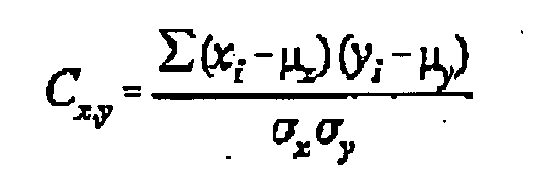
where:
Cx,y is a correlation coefficient;
Xi is a value in the first portion of the sensed value set; the values ranging from
one to n, n being the total number of values in the first portion of the sensed value
set;
yl is the value corresponding to the position of xi in the first portion of the stored value set;
µx is the average of the values in the first portion of the sensed value set.
µy is the average of the values in the first portion of the stored value set;
σx is the standard deviation of the values in the first portion of the sensed value
set; and
σy is the standard deviation of the values in the first portion of the stored value
set.
33. The apparatus according to claim 32 wherein said circuit is operative to generate
a sensed value set having a first portion including reflectance values generated responsive
to radiation from each of said types of emitter, and to calculate a value representative
of a level of correlation with the first portion of each of a seventh plurality of
stored value sets corresponding to reflectance values from each of said types of emitters.
34. The apparatus according to claim 32 wherein said circuit is operative to generate
a sensed value set having a first portion including transmission values generated
responsive to radiation from each of said types of emitter, and to calculate a value
representative of a level of correlation with the first portion of each of a seventh
plurality of stored value sets corresponding to transmission values from each of said
types of emitter.
35. The apparatus according to claim 34 wherein said stored value sets include reflectance
or transmission values corresponding to each of said plurality of known note types
shifted in the note direction from said note.
36. The apparatus according to claim 34 wherein said stored value sets include transmission
or reflectance values corresponding to each of said plurality of known note types
shifted in a direction transverse of said note direction from said note.
37. The apparatus according to claim 1 wherein said radiation source comprises a second
plurality of radiation emitters, said emitters including a third plurality of emitter
types, wherein each type of emitter generates radiation at a wavelength different
from the other types, and wherein all of said emitters direct radiation at one test
spot on said note, and wherein at least one of said first or second detectors is positioned
adjacent said test spot.
38. The apparatus according to claim 37 wherein said circuit is operative to generate
a sensed value set including a first portion corresponding to either transmission
or reflectance values for one of said emitter types, and wherein said circuit is operative
to generate stored value sets including said stored values, and wherein said stored
value sets each include a first corresponding portion wherein said each said first
corresponding portion of a stored value set corresponds to said transmission or reflectance
values for said one type emitter and a known note type, and wherein said circuit is
operative to calculate said value representative of level of correlation between said
first portion of said sensed value set and said first corresponding portion of each
stored value set.
39. The apparatus according to claim 38 wherein said circuit is operative to produce a
sensed value set including a fourth plurality of portions, each portion corresponding
to reflectance or transmission values from each of said third plurality of emitter
types, and wherein said circuit is operative to generate stored value sets, each said
stored value set including said fourth plurality of corresponding portions corresponding
to said transmission or reflectance values for each of said emitter types and a known
note type, and wherein said circuit calculates said value representative of a level
of correlation for each portion of the sensed value set and each corresponding portion
of each stored value set.
40. The apparatus according to claim 39 wherein the circuit is operative to calculate
said value representative of the level of correlation between the sensed value set
and each stored value set, by combining values representative of the level of correlation
between the corresponding portions of the sensed value set and each stored value set.
41. The apparatus according to claim 39 wherein said circuit is operative to calculate
a value representative of the overall level of correlation between the sensed value
set and a stored value set by multiplying together values representative of a level
of correlation of reflectance values in corresponding portions of the sensed value
set and the stored value set to obtain a reflectance product which corresponds to
an overall level of correlation for reflectance between the sensed value set and the
stored value set, wherein said circuit is further operative to multiply together values
representative of the level of correlation of the transmission values in corresponding
portions of the sensed value set and the stored value set to obtain a transmission
product which corresponds to an overall level of correlation for transmission between
the sensed value set and the stored value set, and wherein said circuit is further
operative to produce the value representative of the overall level of correlation
between the sensed value set and the stored value set by multiplying the transmission
product and the reflectance product together.
42. The apparatus according to claim 1 wherein said note has a position and wherein said
stored values include data representative of templates of stored values corresponding
to reflectance and transmission values for each of said plurality of known note types
in said note position and in positions disposed from said note position.
43. The apparatus according to claim 42 wherein said note extends generally in a plane
and wherein said templates correspond to said known note types shifted from said note
position in a first direction in said plane.
44. The apparatus according to claim 43 wherein said templates correspond to said known
note types shifted from said note position in a direction transverse of said first
direction.
45. The apparatus according to claim 40 wherein said circuit is operative to generate
a signal corresponding to a stored value set providing the value representative of
the highest level of correlation with said sensed value set, whereby said signal is
indicative of a particular note type.
46. The apparatus according to claim 45 wherein said circuit is operative to compare said
value representative of said highest level of correlation to a stored threshold value,
and wherein said circuit is operative to provide a second signal when said value representative
of the highest level correlation does not exceed said stored threshold value.
47. The apparatus according to claim 1 wherein said stored values correspond to each of
said plurality of note types in a second plurality of angular positions.
48. The apparatus according to claim 44 wherein said stored value sets correspond to each
of said known note types shifted from said note position in a second plurality angular
directions.
49. The apparatus according to claim 1 wherein said apparatus comprises means for sensing
an angle of skew of said note, and wherein said circuit is operative to select said
stored values used for calculating said value representative of the level of correlation
from said data store responsive to said sensed angle of skew.
50. The apparatus according to claim 27 wherein said circuit is operative to determine
a skew angle of said note responsive to said spot sensing assemblies first sensing
a transmission or reflectance property of said note at different times, and wherein
said stored values used for calculating said value representative of a level of correlation
are selected by said circuit responsive to said skew angle.
51. The apparatus according to claim 50 wherein said skew angle is calculated by said
circuit responsive to a transmission or reflectance value from a first emitter type
in a first spot sensing assembly reaching a threshold value, and said transmission
or reflectance value for said first emitter type in a second spot sensing assembly
transversely spaced from said first spot sensing assembly reaching said threshold
value a time thereafter.
52. The apparatus according to claim 51 wherein said circuit calculates said skew angle
as a function of said time, a distance separating said first and second spot sensing
assemblies, or a speed at which said transport moves said note.
53. The apparatus according to claim 47 wherein said circuit is operative to generate
stored value sets, wherein said value representative of a_level of correlation is
calculated between said reflectance and said transmission values and said stored value
sets, and wherein said circuit is operative to selectively include stored values from
said data store in said stored value sets responsive to said skew angle.
54. The apparatus according to claim 53 wherein said data store includes data representative
of at least one template corresponding to each one of said plurality of known note
types, and wherein said template includes values corresponding to transmission and
reflectance values for said corresponding note type at a generally zero skew angle,
and wherein said circuit generates said stored value set from said template responsive
to said skew angle.
55. The apparatus according to claim 54 wherein said data store includes at least one
said template for each of one of said plurality known note types, wherein said template
includes stored values corresponding to said reflection and transmission values for
said note type at a third plurality of transverse positions.
56. The apparatus according to claim 55 wherein said apparatus further comprises a transport
for relatively moving said note in a note direction relative to said radiation source
and said detectors, and wherein said relatively moving note includes a fourth plurality
of test spots, and wherein each of said test spots is separated from each adjacent
test spot in said note direction by a spot spacing distance, and wherein each said
template includes stored values corresponding to said reflectance and transmission
values for each one of said known note types in uniform increments smaller than said
spot spacing distance.
57. The apparatus according to claim 56 wherein said increments are generally one-fourth
of said spot spacing distance.
58. The apparatus according to claim 56 wherein said data store includes for each one
of said plurality of note types a master template (70), and wherein each said master
template comprises a fifth plurality of sub-templates corresponding to one note type,
and wherein each of said master templates corresponds to said note type at a zero
skew angle, and wherein each of said sub-templates in one of the master templates
corresponds to transmission and reflectance values for said one note type disposed
from an adjacent sub-template in a direction transverse of said note direction, and
wherein said circuit is operative to include values in said stored value sets for
said one note type from said sub-templates in the one master template responsive to
said skew angle.
59. The apparatus according to claim 1 wherein said circuit comprises a digital signal
processor (136), and wherein said data store includes data representative of at least
one template corresponding to a known note type and having said stored values therein
corresponding to said note type in a second plurality of note positions, and wherein
said stored values comprising said template are accessed by said digital processor
of said circuit.
60. The apparatus according to claim 59 wherein said circuit includes a third plurality
of digital signal processors, and wherein each of said digital signal processors accesses
stored values in templates associated with one particular digital signal processor.
61. The apparatus according to claim 60 wherein said circuit is operative to calculate
a correlation value corresponding to a highest level of correlation between said sensed
reflectance and transmission values for said note and the stored values in each one
of said templates.
62. The apparatus according to claim 61 wherein said circuit is further operative to generate
a signal representative of said highest of said correlation values among all of said
templates, whereby said signal is indicative that the sensed note has a highest level
of correlation with stored values for a particular note type.
63. The apparatus according to claim 61 wherein said correlation value is a function of
a transmission correlation value and a reflectance correlation value, wherein said
function is calculated by said circuit, and wherein said transmission correlation
value is calculated by said circuit and is indicative of a level of correlation between
said sensed transmission values and stored values in said template corresponding to
transmission values, and wherein said reflectance correlation value is calculated
by said circuit and is indicative of a level of correlation between said sensed reflectance
values and said stored values in said template corresponding to reflectance values.
64. The apparatus according to claim 63 wherein said radiation source comprises a fourth
plurality of emitter types, wherein each emitter type emits radiation at a generally
different wavelength from other emitter types, and wherein said circuit is operative
to calculate said transmission correlation value as a combination of calculated emitter
type correlation values representative of levels of correlation between transmission
values from said note for each one of said emitter types, and stored values in said
templates corresponding to each one of said emitter types.
65. The apparatus according to claim 63 wherein said radiation source comprises a fourth
plurality of emitter types and wherein said circuit is operative to calculate said
reflectance correlation value responsive to a level of correlation between said reflectance
values from said note for each one of said emitter types, and stored values in said
templates corresponding to each one of said emitter types.
66. The apparatus according to claim 64 wherein said circuit is operative to generate
reflectance and transmission values for a fifth plurality of generally linearly aligned
test spots, whereby said test spots extend in a line on said note, and wherein said
note reflectance and transmission correlation values are calculated by said circuit
for all test spots in said line for each one of said emitter types by calculating
a value representative of a level of correlation with stored values in each of said
templates corresponding to said line and emitter type.
67. The apparatus according to claim 66 wherein said circuit is operative to generate
reflectance and transmission values corresponding to a sixth plurality of lines of
test spots, and wherein said transmission and reflectance correlation values are calculated
by said circuit from stored values in each said template corresponding to each said
line of test spots and emitter type.
68. A method for determining a type associated with a note, comprising the steps of:
illuminating a test spot (34) on said note (30) with a radiation source;
sensing with a first detector (20) radiation reflected from said test spot and generating
a first signal responsive to said reflected radiation sensed;
sensing with a second detector (22) radiation transmitted through said test spot and
generating a second signal responsive to said transmitted radiation sensed;
calculating with a circuit (24) a value representative of a level of correlation between
said first and second signals and stored values in a data store (26) corresponding
to transmission and reflectance properties adjacent said test spot for a plurality
of known note types.
69. The method according to claim 68 wherein said stored values are arranged in stored
value sets, each said stored value set corresponding to one of said known note types,
and further comprising the step of providing a signal indicative of the known note
type having the highest value representative of the level of correlation with said
first and second signals.
70. The method according to claim 68 wherein said illuminating step comprises illuminating
said test spot sequentially with a second plurality of types of radiation emitters
(32) each emitter type emitting radiation at a generally different wavelength than
other emitter types.
71. The method according to claim 70 wherein in said first sensing step said second plurality
of first signals are generated each corresponding to an emitter type, and wherein
in said calculating step a first correlation value is calculated representative of
a level of correlation between each of said first signals for said note and-first
stored values corresponding to reflectance from said emitter type for each of said
plurality of known note types.
72. The method according to claim 71 wherein in said second sensing step said second plurality
of second signals are generated each corresponding to an emitter type, and wherein
in said calculating step a second correlation value is calculated representative of
a level of correlation between each of said second signals for said note and second
stored values corresponding to transmission from said corresponding emitter type through
each of said plurality of known note types.
73. The method according to claim 72 wherein said calculating step comprises calculating
said first and second correlation values for said note and each of said plurality
of known note types, which said value representative of a level of correlation is
calculated as a function of said first and second correlation values.
74. The method according to claim 72 and further comprising the step of conducting said
first and second sensing steps adjacent a third plurality of test spots on said note,
said test spots arranged in a grid, and wherein said first and second stored values
are representative of transmission and reflectance properties adjacent each of said
test spots in said grid for each of said known note types, and said values are stored
as data representative of a template in said data store, and wherein said calculating
step comprises generating with said circuit a stored value set including values from
each template, and calculating said value representative of a level of correlation
as a function of values corresponding to said first and second signals for each of
said test spots on said note and said first and second values in each of said stored
value sets.
75. The method according to claim 68 wherein said illuminating step comprises illuminating
a second plurality of test spots on a grid on said note, each test spot being sequentially
illuminated by a third plurality of types of radiation emitters, each type of radiation
emitter producing radiation at a generally different wavelength from other types of
emitters, and wherein said first and second sensing steps comprise generating first
and second signals at each of said second plurality of test spots for each of said
third plurality of emitters, and wherein said calculating step comprises generating
with said circuit reflectance and transmission values responsive to each of said first
signals and second signals respectively, and wherein said reflectance and transmission
values are placed in a sensed value set, and wherein said calculating step further
comprises generating with said circuit stored value sets comprising stored values
from said data store, and wherein said stored value sets correspond to transmission
and reflectance values for each of said plurality of known note tyres, and wherein
said value representative of a level of correlation is calculated for said sensed
value set and each of said stored value sets.
76. The method according to claim 75 and prior to said illuminating step further comprising
the step of storing in said data store stored values corresponding to said transmission
and reflectance values for each emitter type adjacent each test spot for each of said
known note types disposed in a fourth plurality of spatial positions.
77. The method according to claim 68 and prior to said calculating step further comprising
the step of determining a skew angle of said note from said first and second signals,
and wherein in said calculating step said stored values are selected from said data
store responsive to said skew angle, and wherein said value representative of a level
of correlation is calculated by said circuit using said selected values.
1. Vorrichtung zum Bereitstellen einer Anzeige eines Notentyps, der zu einer durch die
Vorrichtung erfaßten Note gehört, wobei die Vorrichtung aufweist:
eine Strahlungsquelle auf einer ersten Seite der Note (30), welche Strahlung auf einen
Testpunkt (34) auf der Note richtet,
einen ersten Detektor (20) auf der ersten Seite der Note, welcher in Reaktion auf
Strahlung, die von dem Testpunkt zu dem ersten Detektor reflektiert wird, ein erstes
Signal ausgibt,
einen zweiten Detektor (22) auf einer zweiten, gegenüberliegenden Seite der Note,
welcher in Reaktion auf Strahlung, die durch den Testpunkt zu dem zweiten Detektor
transmittiert wird, ein zweites Signal ausgibt,
einen Schaltkreis (24), der mit einem Datenspeicher (26) funktionsfähig verbunden
ist und so betreibbar ist, daß er die Strahlungsquelle aktiviert und daß er in Reaktion
auf das erste bzw. das zweite Signal Reflexions- und Transmissionswerte erzeugt, und
wobei der Schaltkreis so betreibbar ist, daß er wenigstens einen Wert, der ein Korrelationsniveau
zwischen den Reflexions- und Transmissionswerten und gespeicherten Werten in dem Datenspeicher,
die Transmissions- und Reflexionseigenschaften neben dem Testpunkt entsprechen, repräsentiert,
für jeden aus einer Mehrzahl von bekannten Notentypen berechnet.
2. Vorrichtung nach Anspruch 1, wobei die Strahlungsquelle eine zweite Mehrzahl von Strahlungsemittern
(32) aufweist, von denen jeder Strahlung bei einer anderen Wellenlänge erzeugt, und
der Schaltkreis so betreibbar ist, daß er in Reaktion auf von jedem Emitter erzeugte
Strahlung Transmissions- und Reflexionswerte erzeugt, die den ersten und zweiten Signalen
entsprechen.
3. Vorrichtung nach Anspruch 2, wobei der Schaltkreis so betreibbar ist, daß er jeden
Emitter separat betätigt.
4. Vorrichtung nach Anspruch 2, wobei die Emitter im allgemeinen den ersten Detektor
umgebend angeordnet sind.
5. Vorrichtung nach Anspruch 2, wobei die Emitter Strahlung emittieren, die sich im allgemeinen
über den sichtbaren Bereich des Lichts erstreckt.
6. Vorrichtung nach Anspruch 2, wobei die Emitter Emitter beinhalten, die sichtbare und
nicht sichtbare Strahlung emittieren.
7. Vorrichtung nach Anspruch 6, wobei die Emitter einen im allgemeinen roten Emitter,
einen im allgemeinen blauen Emitter, einen im allgemeinen grünen Emitter und einen
Emitter, der im allgemeinen ein Infrarot-Emitter ist, beinhalten.
8. Vorrichtung nach Anspruch 1, wobei ein Satz von erfaßten Werten die Reflexions- und
Transmissionswerte beinhaltet und die gespeicherten Werte in Sätzen von gespeicherten
Werten angeordnet sind und der Schaltkreis so betreibbar ist, daß er das Korrelationsniveau
für den Satz von erfaßten Werten und jeden Satz von gespeicherten Werten berechnet.
9. Vorrichtung nach Anspruch 8, wobei die Strahlungsquelle eine Mehrzahl von Strahlungsemittern
aufweist, von denen jeder Strahlung bei einer im allgemeinen unterschiedlichen Wellenlänge
erzeugt, und der Schaltkreis so betreibbar ist, daß er in Reaktion auf die zweiten
Signale, die in Reaktion auf Strahlung von jedem Emitter erzeugt wurden, Transmissionswerte
erzeugt, und wobei ein Transmissionswert, der Strahlung von einem Emitter entspricht,
in einem ersten Teil eines Satzes von erfaßten Werten enthalten ist, und ein Satz
von Transmissionswerten, die einem weiteren Emitter entsprechen, in einem zweiten
Teil eines Satzes von erfaßten Werten enthalten ist, und wobei die Sätze von gespeicherten
Werten erste und zweite Teile beinhalten und ein Korrelationsniveau zwischen den ersten
Teilen der Sätze von erfaßten und gespeicherten Werten bzw. den zweiten Teilen der
Sätze von erfaßten und gespeicherten Werten berechnet wird.
10. Vorrichtung nach Anspruch 8, wobei die Strahlungsquelle Strahlungsemitter aufweist,
von denen jeder Strahlung bei einer im allgemeinen unterschiedlichen Wellenlänge erzeugt,
und der Schaltkreis so betreibbar ist, daß er in Reaktion auf die ersten Signale,
die in Reaktion auf Strahlung von jedem Emitter erzeugt wurden, Reflexionswerte erzeugt,
und wobei ein Reflexionswert, der Strahlung von einem Emitter entspricht, in einem
ersten Teil des Satzes von erfaßten Werten enthalten ist, und ein Reflexionswert,
der einem weiteren Emitter entspricht, in einem zweiten Teil des Satzes von erfaßten
Werten enthalten ist, und jeder der Sätze von gespeicherten Werten erste und zweite
Teile beinhaltet, und wobei durch den Schaltkreis ein Korrelationsniveau zwischen
den ersten Teilen der Sätze von erfaßten und gespeicherten Werten bzw. den zweiten
Teilen der Sätze von erfaßten und gespeicherten Werten berechnet wird.
11. Vorrichtung nach Anspruch 8, wobei die Strahlungsquelle eine Mehrzahl von Strahlungsemittern
aufweist und jeder der Emitter Strahlung bei einer im allgemeinen unterschiedlichen
Wellenlänge erzeugt und der Schaltkreis so betreibbar ist, daß er in Reaktion auf
die von jedem Emitter erzeugte Strahlung einen Reflexionswert und einen Transmissionswert
erzeugt, und jeder der Reflexions- und Transmissionswerte in einem Satz von erfaßten
Daten enthalten ist.
12. Vorrichtung nach Anspruch 11, wobei der Schaltkreis so betreibbar ist, daß er jeden
Emitter getrennt von den anderen aktiviert, wobei Reflexions- und Transmissionswerte
für jeden Emitter gleichzeitig erzeugt werden.
13. Vorrichtung nach Anspruch 1, die weiterhin eine Notentransporteinrichtung aufweist,
welche die Note und die ersten und zweiten Detektoren relativ zueinander bewegt, wobei
aufgrund der relativen Bewegung die Note eine zweite Mehrzahl von diskreten Testpunkten
aufweist und der Schaltkreis für jeden der Testpunkte Reflexions- und Transmissionswerte
erzeugt und die gespeicherten Werte Transmissions- und Reflexionseigenschaften neben
jedem der Testpunkte für jeden aus der Mehrzahl von bekannten Notentypen entsprechen.
14. Vorrichtung nach Anspruch 13, wobei die Strahlungsquelle eine dritte Mehrzahl von
Strahlungsemittertypen aufweist, von denen jeder Strahlung bei einer im allgemeinen
unterschiedlichen Wellenlänge erzeugt, und der Schaltkreis so betreibbar ist, daß
er jeden Emittertyp separat und in einer Abfolge benachbart zu jedem aus der zweiten
Mehrzahl von Testpunkten aktiviert.
15. Vorrichtung nach Anspruch 14, wobei die zweite Mehrzahl von Transmissionswerten, die
einem ersten Emitter entsprechen, in einem ersten Teil eines Satzes von erfaßten Daten
enthalten ist, und der Datenspeicher eine vierte Mehrzahl von ersten Sätzen von gespeicherten
Werten enthält, die jeweils einen ersten Teil haben, der Transmissionseigenschaften
neben jedem der Testpunkte für jeden aus der Mehrzahl von bekannten Notentypen entspricht,
und der Schaltkreis so betreibbar ist, daß er den Wert berechnet, der das Korrelationsniveau
zwischen dem ersten Teil des Satzes von erfaßten Werten und den ersten Teilen eines
jeden aus der vierten Mehrzahl von Sätzen von gespeicherten Werten repräsentiert.
16. Vorrichtung nach Anspruch 14, wobei die zweite Mehrzahl von Reflexionswerten, die
einem ersten Emitter entsprechen, in einem ersten Teil eines Satzes von erfaßten Daten
enthalten ist, und der Datenspeicher eine vierte Mehrzahl von ersten Sätzen von gespeicherten
Werten enthält, die jeweils einen ersten Teil haben, der Reflexionseigenschaften neben
jedem der Testpunkte für jeden aus der Mehrzahl von bekannten Notentypen entspricht,
und der Schaltkreis so betreibbar ist, daß er den Wert berechnet, der das Korrelationsniveau
zwischen dem ersten Teil des Satzes von erfaßten Werten und den ersten Teilen eines
jeden aus der vierten Mehrzahl von Sätzen von gespeicherten Werten repräsentiert.
17. Vorrichtung nach Anspruch 15, wobei die Notentransporteinrichtung die Note in einer
Notenrichtung bewegt und die ersten und zweiten Detektoren und die dritte Mehrzahl
von Emittern einen Punktabtastaufbau (18) aufweisen und die Vorrichtung eine fünfte
Mehrzahl von Punktabtastaufbauten aufweist, die im allgemeinen schräg bzw. quer zur
Notenrichtung in einem Abstand angeordnet sind, und der erste Teil des Satzes von
erfaßten Daten Transmissionswerte enthält, die dem einen ersten Emitter in einem aus
der fünften Mehrzahl von Punktabtastaufbauten entsprechen, wobei die Transmissionswerte
Strahlung entsprechen, die während der relativen Bewegung der Note durch die Notentransporteinrichtung
an jedem der Testpunkte neben einem aus der fünften Mehrzahl von Punktabtastaufbauten
durch die Note transmittiert wird.
18. Vorrichtung nach Anspruch 15, wobei die Notentransporteinrichtung die Note in einer
Notenrichtung bewegt und die ersten und zweiten Detektoren und die dritte Mehrzahl
von Emittern einen Punktabtastaufbau aufweisen und die Vorrichtung weiterhin eine
fünfte Mehrzahl von Punktabtastaufbauten aufweist, die im allgemeinen quer zur Notenrichtung
im Abstand angeordnet sind, und der erste Teil des Satzes von erfaßten Daten Reflexionswerte
enthält, die dem einen ersten Emitter und einem aus der fünften Mehrzahl von Punktabtastaufbauten
entsprechen, wobei die Reflexionswerte Strahlung entsprechen, die während der relativen
Bewegung der Note durch die Notentransporteinrichtung von der Note an jedem der Testpunkte
neben einem aus der fünften Mehrzahl von Punktabtastaufbauten reflektiert wird.
19. Vorrichtung nach Anspruch 15, wobei der Schaltkreis so betreibbar ist, daß er Sätze
von gespeicherten Werten erzeugt, wobei die Sätze von gespeicherten Werten Datenwerte
aus dem Datenspeicher aufweisen und die Sätze von gespeicherten Werten Transmissionswerte
für jeden aus der Mehrzahl von bekannten Notentypen von jedem der Emitter neben jedem
aus der zweiten Mehrzahl von Testpunkten aufweisen.
20. Vorrichtung nach Anspruch 16, wobei der Schaltkreis so betreibbar ist, daß er Sätze
von gespeicherten Werten erzeugt, welche gespeicherte Werte aus dem Datenspeicher
aufweisen, und die Sätze von gespeicherten Werten Reflexionswerte für jeden aus der
Mehrzahl von bekannten Notentypen von jedem der Emitter neben jedem aus der zweiten
Mehrzahl von Testpunkten aufweisen.
21. Vorrichtung nach Anspruch 19, wobei die zweite Mehrzahl von Testpunkten im allgemeinen
im gleichen Abstand voneinander angeordnet ist und der Datenspeicher Datenwerte enthält,
die Transmissionswerten für jeden aus der Mehrzahl von bekannten Notentypen, die im
Abstand voneinander zwischen jedem der Testpunkte auf der Note liegen, entsprechen,
wodurch eine Position einer Kante der Note nicht festgestellt werden muß, um den Notentyp
zu identifizieren.
22. Vorrichtung nach Anspruch 20, wobei die zweite Mehrzahl von Testpunkten im allgemeinen
im gleichen Abstand voneinander angeordnet sind und der Datenspeicher Datenwerte enthält,
die Reflexionswerten für jeden aus der Mehrzahl von bekannten Notentypen entsprechen,
die zwischen jedem der Testpunkte auf der Note im Abstand angeordnet sind, wodurch
eine Position einer Kante der Note nicht erfaßt werden muß, um den Notentyp zu identifizieren.
23. Vorrichtung nach Anspruch 19, wobei die Notentransporteinrichtung die Note relativ
zu den Detektoren in einer Notenrichtung bewegt und der Datenspeicher Datenwerte enthält,
die Transmissionswerten für jeden aus der Mehrzahl von bekannten Notentypen entsprechen,
die um wenigstens ein Inkrement in einer Richtung quer zu der Notenrichtung zu der
Note versetzt sind, so daß die Note in der Transporteinrichtung nicht in Querrichtung
ausgerichtet werden muß, um den Notentyp zu identifizieren.
24. Vorrichtung nach Anspruch 20, wobei die Notentransporteinrichtung die Note relativ
zu den Detektoren in einer Notenrichtung bewegt und der Datenspeicher Datenwerte enthält,
die Reflexionswerten für jeden aus der Mehrzahl von bekannten Notentypen entsprechen,
die um wenigstens ein Inkrement in einer Richtung quer zu der Notenrichtung zu der
Note versetzt sind, so daß die Note in der Notentransporteinrichtung nicht in Querrichtung
ausgerichtet werden muß, um den Notentyp zu identifizieren.
25. Vorrichtung nach Anspruch 21, wobei die Notentransporteinrichtung die Note relativ
zu den Detektoren in einer Notenrichtung bewegt und der Datenspeicher Datenwerte enthält,
die Transmissionswerten für jeden aus der Mehrzahl von bekannten Notentypen entsprechen,
die um wenigstens ein Inkrement in einer Richtung quer zu der Notenrichtung zu der
Note versetzt sind, so daß die Noten in der Transporteinrichtung nicht ausgerichtet
werden müssen, um ihre Typen zu identifizieren.
26. Vorrichtung nach Anspruch 22, wobei die Notentransporteinrichtung die Note relativ
zu den Detektoren in einer Notenrichtung bewegt und der Datenspeicher Datenwerte enthält,
die Reflexionswerten für jeden aus der Mehrzahl von bekannten Notentypen entsprechen,
die um wenigstens ein Inkrement in einer Richtung quer zu der Notenrichtung zu der
Note versetzt sind, so daß Noten in der Transporteinrichtung nicht ausgerichtet werden
müssen, um ihre Typen zu identifizieren.
27. Vorrichtung nach Anspruch 2, wobei der erste Detektor, der zweite Detektor und die
zweite Mehrzahl von Strahlungsemittern einen Punktabtastaufbau aufweisen und die Vorrichtung
eine Notentransporteinrichtung aufweist und die Notentransporteinrichtung die Note
relativ zu dem Punktabtastaufbau in einer Notenrichtung bewegt und die Vorrichtung
eine fünfte Mehrzahl von Punktabtastaufbauten aufweist und die Punktabtastaufbauten
in Querrichtung relativ zu der Notenrichtung voneinander beabstandet sind.
28. Vorrichtung nach Anspruch 27, wobei der Schaltkreis jeden der Emitter in jedem der
Punktabtastaufbauten eine sechste Mehrzahl von Malen aktiviert, wenn sich die Note
in relativer Richtung in eine benachbarte Beziehung zu den Punktabtastaufbauten bewegt.
29. Vorrichtung nach Anspruch 28, wobei der Schaltkreis die Emitter gemäß einer zeitlich
abgestimmten Abfolge aktiviert.
30. Vorrichtung nach Anspruch 29, wobei der Schaltkreis die Emitter so aktiviert, daß
die Erzeugung der Transmissions- und Reflexionswerte für die von jedem Emitter emittierte
Strahlung in jedem der Punktabtastaufbauten an einem Gitter aus Testpunkten auf der
Note bewirkt wird.
31. Vorrichtung nach Anspruch 30, wobei Emitter eines Typs Strahlung bei im allgemeinen
der gleichen Wellenlänge erzeugen und die Transmissions- oder Reflexionswerte, die
Strahlung von einem Emittertyp an jedem der Testpunkte in einem Teil des Gitters entsprechen,
einen ersten Teil eines Satzes von erfaßten Daten aufweisen und der Datenspeicher
gespeicherte Werte enthält, wobei der Schaltkreis einen Satz von gespeicherten Werten
erzeugt, die einen ersten Teil haben, der den Transmissions- oder Reflexionswerten
an den Testpunkten in dem Gitter, die dem einen Emittertyp für jeden aus der Mehrzahl
von bekannten Notentypen entsprechen, entspricht.
32. Vorrichtung nach Anspruch 31, wobei der erste Teil des Satzes von erfaßten Werten
mit (x) bezeichnete Werte aufweist und der erste Teil der Sätze von gespeicherten
Werten mit (y) bezeichnete gespeicherte Werte aufweist und der Schaltkreis so betreibbar
ist, daß er den Wert, der das Korrelationsniveau zwischen dem ersten Teil des Satzes
von erfaßten Werten und dem ersten Teil der Sätze von zweiten Werten repräsentiert,
gemäß der folgenden Formel berechnet:
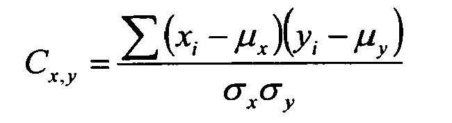
worin:
Cx,y ein Korrelationskoeffizient ist,
Xi ein Wert in dem ersten Teil des Satzes von erfaßten Werten ist, wobei die Werte im
Bereich von eins bis n liegen und n die Gesamtzahl an Werten in dem ersten Teil des
Satzes von erfaßten Werten ist,
yi der Wert ist, welcher der Position von xi in dem ersten Teil des Satzes von gespeicherten Werten entspricht,
µx der Mittelwert der Werte in dem ersten Teil des Satzes von erfaßten Werten ist,
µy der Mittelwert der Werte in dem ersten Teil des Satzes von gespei- cherten Werten
ist,
σx die Standardabweichung der Werte in dem ersten Teil des Satzes von erfaßten Werten
ist und
σy die Standardabweichung der Werte in dem ersten Teil des Satzes von gespeicherten
Werten ist.
33. Vorrichtung nach Anspruch 32, wobei der Schaltkreis so betreibbar ist, daß er einen
Satz von erfaßten Werten mit einem ersten Teil, der Reflexionswerte enthält, die in
Reaktion auf Strahlung von jedem der Emittertypen erzeugt wurden, erzeugt und einen
Wert berechnet, der ein Korrelationsniveau mit dem ersten Teil eines jeden aus einer
siebten Mehrzahl von Sätzen von gespeicherten Werten, die Reflexionswerten von jedem
der Emittertypen entsprechen, repräsentiert.
34. Vorrichtung nach Anspruch 32, wobei der Schaltkreis so betreibbar ist, daß er einen
Satz von erfaßten Werten mit einem ersten Teil, der Transmissionswerte enthält, die
in Reaktion auf Strahlung von jedem der Emittertypen erzeugt wurden, erzeugt und einen
Wert berechnet, der das Korrelationsniveau mit dem ersten Teil eines jeden aus einer
siebten Mehrzahl von Sätzen von gespeicherten Werten, die Transmissionswerten von
jedem der Emittertypen entsprechen, repräsentiert.
35. Vorrichtung nach Anspruch 34, wobei die Sätze von gespeicherten Werten Reflexions-
oder Transmissionswerte aufweisen, die jedem aus der Mehrzahl von bekannten Notentypen
entsprechen und in der Notenrichtung zu der Note versetzt sind.
36. Vorrichtung nach Anspruch 34, wobei die Sätze von gespeicherten Werten Transmissions-
oder Reflexionswerte aufweisen, die jedem aus der Mehrzahl von bekannten Notentypen
entsprechen und in einer Richtung quer zu der Notenrichtung zu der Note versetzt sind.
37. Vorrichtung nach Anspruch 1, wobei die Strahlungsquelle eine zweite Mehrzahl von Strahlungsemittern
aufweist, die eine dritte Mehrzahl von Emittertypen aufweisen, wobei jeder Emittertyp
Strahlung bei einer Wellenlänge erzeugt, die sich von denjenigen der anderen Typen
unterscheidet, und alle Emitter Strahlung auf einen Testpunkt auf der Note richten
und wenigstens der erste und/oder der zweite Detektor neben dem Testpunkt angeordnet
ist.
38. Vorrichtung nach Anspruch 37, wobei der Schaltkreis so betreibbar ist, daß er einen
Satz von erfaßten Werten mit einem ersten Teil, der entweder Transmissions- oder Reflexionswerten
für einen der Emittertypen entspricht, erzeugt, und der Schaltkreis so betreibbar
ist, daß er Sätze von gespeicherten Werten erzeugt, welche die gespeicherten Werte
enthalten, und wobei die Sätze von gespeicherten Werten jeweils einen ersten korrespondierenden
Teil aufweisen, wobei der erste korrespondierende Teil eines Satzes von gespeicherten
Werten den Transmissions- oder Reflexionswerten für den einen Emittertyp und einen
bekannten Notentyp entspricht und der Schaltkreis so betreibbar ist, daß er den Wert
berechnet, der das Korrelationsniveau zwischen dem ersten Teil des Satzes von erfaßten
Werten und dem ersten korrespondierenden Teil jedes Satzes von gespeicherten Werten
repräsentiert.
39. Vorrichtung nach Anspruch 38, wobei der Schaltkreis so betreibbar ist, daß er einen
Satz von erfaßten Werten mit einer vierten Mehrzahl von Teilen erzeugt, wobei jeder
Teil Reflexions- oder Transmissionswerten eines jeden aus der dritten Mehrzahl von
Emittertypen entspricht, und wobei der Schaltkreis so betreibbar ist, daß er Sätze
von gespeicherten Werten erzeugt, wobei jeder Satz von gespeicherten Werten die vierte
Mehrzahl von korrespondierenden Teilen aufweist, die den Transmissions- oder Reflexionswerten
für jeden der Emittertypen und einen bekannten Notentyp entsprechen, und wobei der
Schaltkreis den Wert berechnet, der ein Korrelationsniveau für jeden Teil des Satzes
von erfaßten Werten und jeden korrespondierenden Teil jedes Satzes von gespeicherten
Werten repräsentiert.
40. Vorrichtung nach Anspruch 39, wobei der Schaltkreis so betreibbar ist, daß er den
Wert, der das Korrelationsniveau zwischen dem Satz von erfaßten Werten und jedem Satz
von gespeicherten Werten repräsentiert, berechnet, indem er Werte kombiniert, die
das Korrelationsniveau zwischen den korrespondierenden Teilen des Satzes von erfaßten
Daten und jedem Satz von gespeicherten Daten repräsentieren.
41. Vorrichtung nach Anspruch 39, wobei der Schaltkreis so betreibbar ist, daß er einen
Wert, der das gesamte Korrelationsniveau zwischen dem Satz von erfaßten Werten und
einem Satz von gespeicherten Werten repräsentiert, berechnet, indem er Werte miteinander
multipliziert, die ein Korrelationsniveau von Reflexionswerten in korrespondierenden
Teilen des Satzes von erfaßten Werten und dem Satz von gespeicherten Werten repräsentieren,
unter Erhalt eines Reflexionsprodukts, welches einem gesamten Korrelationsniveau für
die Reflexion zwischen dem Satz von erfaßten Werten und dem Satz von gespeicherten
Werten entspricht, wobei der Schaltkreis weiterhin so betreibbar ist, daß er Werte
miteinander multipliziert, die das Korrelationsniveau der Transmissionswerte in korrespondierenden
Teilen des Satzes von erfaßten Werten und dem Satz von gespeicherten Werten repräsentieren,
unter Erhalt eines Transmissionsprodukts, welches einem gesamten Korrelationsniveau
für die Transmission zwischen dem Satz von erfaßten Werten und dem Satz von gespeicherten
Werten entspricht, und wobei der Schaltkreis weiterhin so betreibbar ist, daß er den
Wert, der das gesamte Korrelationsniveau zwischen dem Satz von erfaßten Werten und
dem Satz von gespeicherten Werten repräsentiert, erzeugt, indem er das Transmissionsprodukt
und das Reflexionsprodukt miteinander multipliziert.
42. Vorrichtung nach Anspruch 1, wobei die Note eine Position hat und die gespeicherten
Werte Daten aufweisen, die Matrizen von gespeicherten Werten repräsentieren, welche
Reflexions- und Transmissionswerten für jeden aus der Mehrzahl von bekannten Notentypen
in der Notenposition und in zu der Notenposition versetzten Positionen entsprechen.
43. Vorrichtung nach Anspruch 42, wobei sich die Note im allgemeinen in einer Ebene erstreckt
und wobei die Matrizen den bekannten Notentypen entsprechen und zu der Notenposition
in einer ersten Richtung in der Ebene versetzt sind.
44. Vorrichtung nach Anspruch 43, wobei die Matrizen den bekannten Notentypen entsprechen
und in einer Richtung quer zu der ersten Richtung zu der Notenposition versetzt sind.
45. Vorrichtung nach Anspruch 40, wobei der Schaltkreis so betreibbar ist, daß er ein
Signal erzeugt, welches einem Satz von gespeicherten Werten entspricht, die den Wert
liefern, welcher dem höchsten Niveau der Korrelation mit dem Satz von erfaßten Werten
entspricht, so daß das Signal einen bestimmten Notentyp anzeigt.
46. Vorrichtung nach Anspruch 45, wobei der Schaltkreis so betreibbar ist, daß er den
Wert, der das höchste Korrelationsniveau repräsentiert, mit einem gespeicherten Schwellwert
vergleicht, und der Schaltkreis so betreibbar ist, daß er ein zweites Signal liefert,
wenn der Wert, der das höchste Korrelationsniveau repräsentiert, den gespeicherten
Schwellwert nicht überschreitet.
47. Vorrichtung nach Anspruch 1, wobei die gespeicherten Werte einem jeden aus der Mehrzahl
von Notentypen in einer zweiten Mehrzahl von abgewinkelten Positionen entsprechen.
48. Vorrichtung nach Anspruch 44, wobei die Sätze von gespeicherten Werten einem jeden
der bekannten Notentypen entsprechen und in einer zweiten Mehrzahl von abgewinkelten
Richtungen zu der Notenposition versetzt sind.
49. Vorrichtung nach Anspruch 1, wobei die Vorrichtung Mittel zum Erfassen eines Schrägungswinkels
der Note aufweist und der Schaltkreis so betreibbar ist, daß er die gespeicherten
Werte, die zum Berechnen des Wertes verwendet werden, welcher das Korrelationsniveau
repräsentiert, in Reaktion auf den erfaßten Schrägungswinkel aus dem Datenspeicher
auswählt.
50. Vorrichtung nach Anspruch 27, wobei der Schaltkreis so betreibbar ist, daß er einen
Schrägungswinkel der Note in Reaktion darauf bestimmt, daß die Punktabtastaufbauten
zuerst eine Transmissions- oder Reflexionseigenschaft der Note zu verschiedenen Zeitpunkten
erfassen, und wobei die gespeicherten Werte, die zum Berechnen des Wertes, der ein
Korrelationsniveau repräsentiert, verwendet werden, von dem Schaltkreis in Reaktion
auf den Schrägungswinkel ausgewählt werden.
51. Vorrichtung nach Anspruch 50, wobei der Schrägungswinkel von dem Schaltkreis in Reaktion
darauf berechnet wird, daß ein Transmissions- oder Reflexionswert von einem ersten
Emittertyp in einem ersten Punktabtastaufbau einen Schwellwert erreicht und danach
der Transmissions- oder Reflexionswert des ersten Emittertyps in einem zweiten Punktabtastaufbau,
der in Querrichtung von dem ersten Punktabtastaufbau beabstandet ist, den Schwellwert
eine Zeit später erreicht.
52. Vorrichtung nach Anspruch 51, wobei der Schaltkreis den Schrägungswinkel als eine
Funktion der Zeit, eines Abstands, um den die ersten und zweiten Punktabtastaufbauten
voneinander getrennt sind, oder einer Geschwindigkeit, mit der die Transporteinrichtung
die Note bewegt, berechnet.
53. Vorrichtung nach Anspruch 47, wobei der Schaltkreis so betreibbar ist, daß er Sätze
von gespeicherten Werten erzeugt, wobei der ein Korrelationsniveau repräsentierende
Wert zwischen den Reflexions- und Transmissionswerten und den Sätzen von gespeicherten
Werten berechnet wird und der Schaltkreis so betreibbar ist, daß er in Reaktion auf
den Schrägungswinkel wahlweise gespeicherte Werte aus dem Datenspeicher in den Sätzen
von gespeicherten Werten aufnimmt.
54. Vorrichtung nach Anspruch 53, wobei der Datenspeicher Daten aufweist, die wenigstens
eine Matrize repräsentieren, die einem jeden aus der Mehrzahl von bekannten Notentypen
entspricht, und die Matrize Werte aufweist, die Transmissions- und Reflexionswerten
für den korrespondierenden Notentyp bei einem Schrägungswinkel von im allgemeinen
null entsprechen, und wobei der Schaltkreis in Reaktion auf den Schrägungswinkel aus
der Matrize einen Satz von gespeicherten Werten erzeugt.
55. Vorrichtung nach Anspruch 54, wobei der Datenspeicher wenigstens eine Matrize für
jeden aus der Mehrzahl von bekannten Notentypen aufweist, wobei die Matrize gespeicherte
Werte enthält, die den Reflexions- und Transmissionswerten für den Notentyp an einer
dritten Mehrzahl von Positionen in Querrichtung entsprechen.
56. Vorrichtung nach Anspruch 55, wobei die Vorrichtung weiterhin eine Transporteinrichtung
für das relative Bewegen der Note in einer Notenrichtung relativ zu der Strahlungsquelle
und den Detektoren aufweist und die sich in relativer Richtung bewegende Note eine
vierte Mehrzahl von Testpunkten aufweist und jeder der Testpunkte von jedem benachbarten
Testpunkt in der Notenrichtung um eine Punktabstandsdistanz getrennt ist und die Matrize
gespeicherte Werte enthält, die Reflexions- und Transmissionswerten für einen jeden
der bekannten Notentypen in einheitlichen Inkrementen, die kleiner sind als die Punktabstandsdistanz,
entsprechen.
57. Vorrichtung nach Anspruch 56, wobei die Inkremente im allgemeinen ein Viertel der
Punktabstandsdistanz betragen.
58. Vorrichtung nach Anspruch 56, wobei der Datenspeicher für einen jeden aus der Mehrzahl
von Notentypen eine Master-Matrize (70) aufweist und jede Master-Matrize eine fünfte
Mehrzahl von Untermatrizen aufweist, die einem Notentyp entsprechen, und jede der
Master-Matrizen dem Notentyp unter einem Schrägungswinkel von null entspricht und
jede der Untermatrizen in einer der Master-Matrizen Transmissions- und Reflexionswerten
für den einen Notentyp entspricht, die von einer benachbarten Untermatrize in einer
Richtung quer zu der Notenrichtung versetzt sind, und wobei der Schaltkreis so betreibbar
ist, daß er in Reaktion auf den Schrägungswinkel Werte in den Sätzen von gespeicherten
Werten für den einen Notentyp aus den Untermatrizen in der einen Master-Matrize aufnimmt.
59. Vorrichtung nach Anspruch 1, wobei der Schaltkreis einen digitalen Signalprozessor
(136) aufweist und der Datenspeicher Daten enthält, die wenigstens eine Matrize repräsentieren,
die einem bekannten Notentyp entspricht und worin Werte gespeichert sind, die dem
Notentyp in einer zweiten Mehrzahl von Notenpositionen entsprechen, und wobei auf
die gespeicherten Werte, die die Matrize bilden, durch den digitalen Prozessor des
Schaltkreises zugegriffen wird.
60. Vorrichtung nach Anspruch 59, wobei der Schaltkreis eine dritte Mehrzahl von digitalen
Signalprozessoren aufweist und jeder der digitalen Signalprozessoren auf gespeicherte
Werte in Matrizen zugreift, die zu einem bestimmten digitalen Signalprozessor gehören.
61. Vorrichtung nach Anspruch 60, wobei der Schaltkreis so betreibbar ist, daß er einen
Korrelationswert berechnet, der einem höchsten Korrelationsniveau zwischen den erfaßten
Reflexions- und Transmissionswerten für die Note und den gespeicherten Werten in jeder
der Matrizen entspricht.
62. Vorrichtung nach Anspruch 61, wobei der Schaltkreis weiterhin so betreibbar ist, daß
er ein Signal erzeugt, welches den höchsten der Korrelationswerte unter allen Matrizen
repräsentiert, so daß das Signal anzeigt, daß die erfaßte Note ein höchstes Korrelationsniveau
mit gespeicherten Werten für einen bestimmten Notentyp hat.
63. Vorrichtung nach Anspruch 61, wobei der Korrelationswert eine Funktion eines Transmissionskorrelationswerts
und eines Reflexionskorrelationswerts ist, wobei die Funktion von dem Schaltkreis
berechnet wird und der Transmissionskorrelationswert von dem Schaltkreis berechnet
wird und ein Korrelationsniveau zwischen den erfaßten Transmissionswerten und gespeicherten
Werten in der Matrize, die Transmissionswerten entsprechen, anzeigt, und der Reflexionskorrelationswert
von dem Schaltkreis berechnet wird und ein Korrelationsniveau zwischen den erfaßten
Reflexionswerten und den gespeicherten Werten in der Matrize, die Reflexionswerten
entsprechen, anzeigt.
64. Vorrichtung nach Anspruch 63, wobei die Strahlungsquelle eine vierte Mehrzahl von
Emittertypen aufweist, wobei jeder Emittertyp Strahlung bei einer Wellenlänge emittiert,
die sich im allgemeinen von derjenigen anderer Emittertypen unterscheidet, und wobei
der Schaltkreis so betreibbar ist, daß er den Transmissionskorrelationswert als eine
Kombination von berechneten Korrelationswerten von Emittertypen berechnet, die Korrelationsniveaus
zwischen Transmissionswerten von der Note für jeden der Emittertypen und gespeicherten
Werten in der Matrize, die einem jeden der Emittertypen entsprechen, repräsentieren.
65. Vorrichtung nach Anspruch 63, wobei die Strahlungsquelle eine vierte Mehrzahl von
Emittertypen aufweist und der Schaltkreis so betreibbar ist, daß er den Reflexionskorrelationswert
in Reaktion auf ein Korrelationsniveau zwischen den Reflexionswerten von der Note
für einen jeden der Emittertypen und gespeicherten Werten in den Matrizen, die einem
jeden der Emittertypen entsprechen, berechnet.
66. Vorrichtung nach Anspruch 64, wobei der Schaltkreis so betreibbar ist, daß er Reflexions-
und Transmissionswerte für eine fünfte Mehrzahl von im allgemeinen linear ausgerichteten
Testpunkten erzeugt, wobei sich die Testpunkte in einer Linie auf der Note erstrecken
und die Reflexions- und Transmissionskorrelationswerte der Note von dem Schaltkreis
für alle Testpunkte in der Linie für jeden der Emittertypen berechnet werden, indem
ein Wert berechnet wird, der ein Korrelationsniveau mit gespeicherten Werten in jeder
der Matrizen entsprechend der Linie und dem Emittertyp repräsentiert.
67. Vorrichtung nach Anspruch 66, wobei der Schaltkreis so betreibbar ist, daß er Reflexions-
und Transmissionswerte erzeugt, die einer sechsten Mehrzahl von Linien von Testpunkten
entsprechen, und die Transmissions- und Reflexionskorrelationswerte von dem Schaltkreis
aus gespeicherten Werten in jeder Matrize entsprechend jeder der Linien von Testpunkten
und Emittertyp berechnet werden.
68. Verfahren zum Bestimmen eines zu einer Note gehörenden Typs, welches die folgenden
Schritte umfaßt:
Beleuchten eines Testpunkts (34) auf der Note (30) mit einer Strahlungsquelle,
Erfassen von von dem Testpunkt reflektierter Strahlung mit einem ersten Detektor (20)
und Erzeugen eines ersten Signals in Reaktion auf die erfaßte reflektierte Strahlung,
Erfassen von durch den Testpunkt transmittierter Strahlung mit einem zweiten Detektor
(22) und Erzeugen eines zweiten Signals in Reaktion auf die erfaßte transmittierte
Strahlung,
Berechnen eines Wertes, der ein Korrelationsniveau zwischen den ersten und zweiten
Signalen und gespeicherten Werten in einem Datenspeicher (26), die Transmissions-
und Reflexionseigenschaften neben dem Testpunkt für eine Mehrzahl von bekannten Notentypen
entsprechen, repräsentiert, mit einem Schaltkreis (24).
69. Verfahren nach Anspruch 68, wobei die gespeicherten Werte in Sätzen von gespeicherten
Werten angeordnet sind, wobei jeder Satz von gespeicherten Werten einem der bekannten
Notentypen entspricht, und wobei das Verfahren weiterhin den Schritt umfaßt, bei dem
ein Signal bereitgestellt wird, welches den bekannten Notentyp mit dem höchsten Wert
anzeigt, welcher das Korrelationsniveau mit den ersten und zweiten Signalen repräsentiert.
70. Verfahren nach Anspruch 68, wobei der Schritt des Beleuchtens das Beleuchten des Testpunkts
nacheinander mit einer zweiten Mehrzahl von Typen von Strahlungsemittem (32) umfaßt,
von denen jeder Strahlung bei einer Wellenlänge emittiert, die sich im allgemeinen
von derjenigen anderer Emittertypen unterscheidet.
71. Verfahren nach Anspruch 70, wobei bei dem Schritt des ersten Erfassens die zweite
Mehrzahl von ersten Signalen erzeugt wird, die jeweils einem Emittertyp entsprechen,
und wobei bei dem Schritt des Berechnens ein erster Korrelationswert berechnet wird,
der ein Korrelationsniveau zwischen jedem der ersten Signale der Note und ersten gespeicherten
Werten, die Reflexionen von dem Emittertyp für jeden aus der Mehrzahl von bekannten
Notentypen entsprechen, repräsentiert.
72. Verfahren nach Anspruch 71, wobei bei dem Schritt des zweiten Erfassens die zweite
Mehrzahl von zweiten Signalen erzeugt wird, die jeweils einem Emittertyp entsprechen,
und wobei bei dem Schritt des Berechnens ein zweiter Korrelationswert berechnet wird,
der ein Korrelationsniveau zwischen jedem der zweiten Signalen für die Note und zweiten
gespeicherten Werten, die der Transmission von dem entsprechenden Emittertyp durch
jeden aus der Mehrzahl von bekannten Notentypen entsprechen, repräsentiert.
73. Verfahren nach Anspruch 72, wobei der Schritt des Berechnens das Berechnen der ersten
und zweiten Korrelationswerte für die Note und einen jeden aus der Mehrzahl von bekannten
Notentypen umfaßt, wobei der Wert, der ein Korrelationsniveau repräsentiert, als eine
Funktion der ersten und zweiten Korrelationswerte berechnet wird.
74. Verfahren nach Anspruch 72, welches weiterhin den Schritt umfaßt, bei dem man die
ersten und zweiten Erfassungsschritte neben einer dritten Mehrzahl von Testpunkten
auf der Note durchführt, wobei die Testpunkte in einem Gitter angeordnet sind und
die ersten und zweiten gespeicherten Werte Transmissions- und Reflexionseigenschaften
neben jedem der Testpunkte in dem Gitter für jeden der bekannten Notentypen repräsentieren
und die Werte als Daten gespeichert werden, die eine Matrize in dem Datenspeicher
repräsentieren, und wobei der Schritt des Berechnens das Erzeugen eines Satzes von
gespeicherten Werten, einschließlich Werten von jeder Matrize, mit dem Schaltkreis
und das Berechnen des Werts, der ein Korrelationsniveau repräsentiert, als eine Funktion
von Werten, die den ersten und zweiten Signalen für jeden der Testpunkte auf der Note
und den ersten und zweiten Werten in jedem der Sätze von gespeicherten Werten entsprechen,
umfaßt.
75. Verfahren nach Anspruch 68, wobei der Schritt des Beleuchtens umfaßt, daß eine zweite
Mehrzahl von Testpunkten in einem Gitter auf der Note beleuchtet wird, jeder Testpunkt
nacheinander von einer dritten Mehrzahl von Typen von Strahlungsemittern beleuchtet
wird, jeder Typ von Strahlungsemittern Strahlung bei einer Wellenlänge erzeugt, die
sich im allgemeinen von derjenigen anderer Emittertypen unterscheidet, und wobei die
ersten und zweiten Erfassungsschritte das Erzeugen erster und zweiter Signale an jedem
aus der zweiten Mehrzahl von Testpunkten für jeden aus der dritten Mehrzahl von Emittern
umfassen, und wobei der Schritt des Berechnens das Erzeugen von Reflexions- und Transmissionswerten
in Reaktion auf jedes der ersten bzw. zweiten Signale mit dem Schaltkreis umfaßt,
und wobei die Reflexions- und Transmissionswerte in einem Satz von erfaßten Daten
angeordnet werden und der Schritt des Berechnens weiterhin das Erzeugen von Sätzen
von gespeicherten Werten aus dem Datenspeicher mit dem Schaltkreis umfaßt und wobei
die Sätze von gespeicherten Werten Transmissions- und Reflexionswerten für jeden aus
der Mehrzahl von bekannten Notentypen entsprechen und wobei der Wert, der ein Korrelationsniveau
repräsentiert, für den Satz von erfaßten Werten und jeden der Sätze von gespeicherten
Werten berechnet wird.
76. Verfahren nach Anspruch 75, welches vor dem Schritt des Beleuchtens weiterhin den
Schritt umfaßt, bei dem in dem Datenspeicher gespeicherte Werte gespeichert werden,
die den Transmissions- und Reflexionswerten für jeden Emittertyp neben jedem Testpunkt
für jeden der bekannten Notentypen, die in einer vierten Mehrzahl von räumlichen Positionen
angeordnet sind, entsprechen.
77. Verfahren nach Anspruch 68, welches vor dem Schritt des Berechnens weiterhin den Schritt
umfaßt, bei dem ein Schrägungswinkel der Note aus den ersten und zweiten Signalen
bestimmt wird, und wobei bei dem Schritt des Berechnens die gespeicherten Werte in
Reaktion auf den Schrägungswinkel aus dem Datenspeicher ausgewählt werden und wobei
der Wert, der ein Korrelationsniveau repräsentiert, von dem Schaltkreis unter Verwendung
der ausgewählten Werte berechnet wird.
1. Appareil pour fournir une indication d'un type de billets de banque associé à un billet
de banque détecté par ledit appareil, comprenant :
une source de rayonnement sur un premier côté dudit billet (30), dans lequel ladite
source de rayonnement dirige un rayonnement vers une zone de test (34) sur ledit billet
;
un premier détecteur (20) sur le premier côté dudit billet, dans lequel ledit premier
détecteur délivre un premier signal en réponse au rayonnement réfléchi de ladite zone
de test vers ledit premier détecteur ;
un deuxième détecteur (22) sur un deuxième côté opposé dudit billet, dans lequel ledit
deuxième détecteur délivre un deuxième signal en réponse au rayonnement transmis à
travers ladite zone de test au dit deuxième détecteur ;
un circuit (24) en connexion opérationnelle avec un magasin de données (26), dans
lequel ledit circuit est opérationnel pour activer ladite source de rayonnement et
pour générer des valeurs de réflectance et de transmission en réponse respectivement
aux dits premier et deuxième signaux, dans lequel ledit circuit est opérationnel pour
calculer au moins une valeur représentative d'un niveau de corrélation entre lesdites
valeurs de réflectance et de transmission et les valeurs stockées dans ledit magasin
de données correspondant aux propriétés de transmission et de réflexion adjacentes
à ladite zone de test pour chacun d'une pluralité de types de billets connus.
2. Appareil selon la revendication 1, dans lequel ladite source de rayonnement comprend
une deuxième pluralité d'émetteurs de rayonnement (32), dans lequel chacun desdits
émetteurs génère un rayonnement à une longueur d'onde différente, et dans lequel ledit
circuit est opérationnel pour générer des valeurs de transmission et de réflectance
correspondant aux dits premier et deuxième signaux en réponse au rayonnement produit
par chaque émetteur.
3. Appareil selon la revendication 2, dans lequel ledit circuit est opérationnel pour
actionner chaque émetteur séparément.
4. Appareil selon la revendication 2, dans lequel lesdits émetteurs sont agencés dans
une relation entourant généralement ledit premier détecteur.
5. Appareil selon la revendication 2, dans lequel lesdits émetteurs émettent un rayonnement
qui couvre généralement la plage de lumière visible.
6. Appareil selon la revendication 2, dans lequel lesdits émetteurs comprennent des émetteurs
qui émettent un rayonnement visible et non visible.
7. Appareil selon la revendication 6, dans lequel lesdits émetteurs comprennent un émetteur
généralement rouge, un émetteur généralement bleu, un émetteur généralement vert,
et un émetteur généralement infrarouge.
8. Appareil selon la revendication 1, dans lequel un ensemble de valeurs détectées comprend
lesdites valeurs de réflectance et de transmission, et dans lequel lesdites valeurs
stockées sont agencées dans des ensembles de valeurs stockées, et dans lequel ledit
circuit est opérationnel pour calculer ledit niveau de corrélation pour l'ensemble
de valeurs détectées et chaque ensemble de valeurs stockées.
9. Appareil selon la revendication 8, dans lequel ladite source de rayonnement comprend
une pluralité d'émetteurs de rayonnement, dans lequel chacun desdits émetteurs de
rayonnement génère un rayonnement à une longueur d'onde généralement différente, et
dans lequel ledit circuit est opérationnel pour générer des valeurs de transmission
en réponse aux dits deuxième signaux produits en réponse au rayonnement de chaque
émetteur, et dans lequel une valeur de transmission correspondant au rayonnement d'un
émetteur est incluse dans une première partie d'un ensemble de valeurs détectées et
un ensemble de valeurs de transmission correspondant à un autre émetteur est inclus
dans une deuxième partie d'un ensemble de valeurs détectées, et dans lequel lesdits
ensembles de valeurs stockées comprennent des premières et deuxièmes parties, et dans
lequel un niveau de corrélation est calculé entre les premières parties des ensembles
de valeurs détectées et stockées et respectivement les deuxièmes parties des ensembles
de valeurs détectées et stockées.
10. Appareil selon la revendication 8, dans lequel ladite source de rayonnement comprend
des émetteurs de rayonnement, dans lequel chacun desdits émetteurs de rayonnement
génère un rayonnement à une longueur d'onde généralement différente, et dans lequel
ledit circuit est opérationnel pour générer des valeurs de réflectance en réponse
aux dits premiers signaux produits en réponse au rayonnement de chaque émetteur, et
dans lequel une valeur de réflectance correspondant au rayonnement d'un émetteur est
incluse dans une première partie de l'ensemble de valeurs détectées et une valeur
de réflectance correspondant à un autre émetteur est incluse dans une deuxième partie
de l'ensemble de valeurs détectées, et dans lequel chacun desdits ensembles de valeurs
stockées comprend des premières et deuxièmes parties, et dans lequel un niveau de
corrélation est calculé par le circuit entre lesdites premières parties desdits ensembles
de valeurs détectées et stockées et respectivement lesdites deuxièmes parties desdits
ensembles de valeurs détectées et stockées.
11. Appareil selon la revendication 8, dans lequel ladite source de rayonnement comprend
une pluralité d'émetteurs de rayonnement, et dans lequel chacun desdits émetteurs
produit un rayonnement à une longueur d'onde généralement différente, et dans lequel
ledit circuit est opérationnel pour générer une valeur de réflectance et une valeur
de transmission en réponse au rayonnement produit par chaque émetteur, et dans lequel
chacune desdites valeurs de réflectance et de transmission est incluse dans un ensemble
de données détectées.
12. Appareil selon la revendication 11, dans lequel ledit circuit est opérationnel pour
activer chaque émetteur séparément des autres, dans lequel les valeurs de réflectance
et de transmission pour chaque émetteur sont générées simultanément.
13. Appareil selon la revendication 1 et comprenant en outre un transport de billets de
banque, et dans lequel ledit transport de billets déplace relativement ledit billet
et lesdits premier et deuxième détecteurs, de telle manière qu'en conséquence dudit
déplacement relatif, ledit billet comprend une deuxième pluralité de zones de test
discrètes, et dans lequel ledit circuit génère des valeurs de réflectance et de transmission
pour chacune desdites zones de test, et dans lequel lesdites valeurs stockées correspondent
à des propriétés de transmission et de réflectance adjacentes à chacune desdites zones
de test pour chacun de ladite pluralité de types de billets connus.
14. Appareil selon la revendication 13, dans lequel ladite source de rayonnement comprend
une troisième pluralité de types d'émetteurs de rayonnement, chaque type d'émetteur
générant un rayonnement à une longueur d'onde généralement différente, et dans lequel
ledit circuit est opérationnel pour activer chaque type d'émetteur séparément et dans
une séquence adjacente à chacune de ladite deuxième pluralité de zones de test.
15. Appareil selon la revendication 14, dans lequel ladite deuxième pluralité de valeurs
de transmission correspondant à un premier émetteur est incluse dans une première
partie d'un ensemble de données détectées, et dans lequel ledit magasin de données
comprend une quatrième pluralité de premiers ensembles de valeurs stockées ayant chacun
une première partie correspondant à des propriétés de transmission adjacentes de chacune
desdites zones de test pour chacun de ladite pluralité de types de billets connus,
et dans lequel ledit circuit est opérationnel pour calculer la valeur représentative
du niveau de corrélation entre ladite première partie dudit ensemble de valeurs détectées
et les premières parties de chacun de ladite quatrième pluralité d'ensembles de valeurs
stockées.
16. Appareil selon la revendication 14, dans lequel ladite deuxième pluralité de valeurs
de réflectance correspondant à un premier émetteur est incluse dans une première partie
d'un ensemble de données détectées, et dans lequel ledit magasin de données comprend
une quatrième pluralité de premiers ensembles de valeurs stockées ayant chacun une
première partie correspondant à des propriétés de réflectance adjacentes à chacune
desdites zones de test pour chacun de ladite pluralité de types de billets connus,
et dans lequel ledit circuit est opérationnel pour calculer la valeur représentative
du niveau de corrélation entre la première partie dudit ensemble de valeurs détectées
et les premières parties de chacun de ladite quatrième pluralité d'ensembles de valeurs
stockées.
17. Appareil selon la revendication 15, dans lequel ledit transport de billets déplace
ledit billet dans une direction de billets, et dans lequel lesdits premier et deuxième
détecteurs et ladite troisième pluralité d'émetteurs comprennent un ensemble de détection
de zones (18), et dans lequel ledit appareil comprend une cinquième pluralité d'ensembles
de détection de zones généralement espacés transversalement par rapport à ladite direction
de billets, et dans lequel ladite première partie dudit ensemble de données détectées
comprend des valeurs de transmission correspondant au dit premier émetteur dans l'un
de ladite cinquième pluralité d'ensembles de détection de zones, lesdites valeurs
de transmission correspondant au rayonnement transmis à travers ledit billet à chacune
desdites zones de test adjacentes à l'un de ladite cinquième pluralité d'ensembles
de détection de zones pendant le déplacement relatif dudit billet par ledit transport
de billets.
18. Appareil selon la revendication 15, dans lequel ledit transport de billets déplace
ledit billet dans une direction de billets, et dans lequel lesdits premier et deuxième
détecteurs et ladite troisième pluralité d'émetteurs comprennent un ensemble de détection
de zones, et dans lequel ledit appareil comprend en outre une cinquième pluralité
d'ensembles de détection de zones généralement espacés transversalement par rapport
à ladite direction de billets, et dans lequel ladite première partie dudit ensemble
de données détectées comprend des valeurs de réflectance correspondant au dit premier
émetteur et à l'un de ladite cinquième pluralité d'ensembles de détection de zones,
lesdites valeurs de réflectance correspondant au rayonnement réfléchi dudit billet
à chacune des zones de test adjacentes à l'un de ladite cinquième pluralité d'ensembles
de détection de zones pendant le déplacement relatif dudit billet par ledit transport
de billets.
19. Appareil selon la revendication 15, dans lequel ledit circuit est opérationnel pour
générer des ensembles de valeurs stockées, dans lequel lesdits ensembles de valeurs
stockées comprennent des valeurs de données dudit magasin de données, dans lequel
lesdits ensembles de valeurs stockées comprennent des valeurs de transmission pour
chacun de ladite pluralité de types de billets connus de chacun desdits émetteurs
adjacents à chacun de ladite deuxième pluralité de zones de test.
20. Appareil selon la revendication 16, dans lequel ledit circuit est opérationnel pour
générer des ensembles de valeurs stockées, dans lequel lesdits ensembles de valeurs
stockées comprennent des valeurs stockées dudit magasin de données, et dans lequel
lesdits ensembles de valeurs stockées comprennent des valeurs de réflectance pour
chacun de ladite pluralité de types de billets connus de chacun desdits émetteurs
adjacents à chacun de ladite deuxième pluralité de zones de test.
21. Appareil selon la revendication 19, dans lequel ladite deuxième pluralité de zones
de test sont généralement espacées uniformément l'une de l'autre, et dans lequel ledit
magasin de données comprend des valeurs de données correspondant aux valeurs de transmission
pour chacun de ladite pluralité de types de billets connus espacé de manière intermédiaire
par rapport à chacune desdites zones de test sur ledit billet, de telle manière qu'il
ne soit pas nécessaire de déterminer un emplacement d'un bord dudit billet pour identifier
ledit type de billets.
22. Appareil selon la revendication 20, dans lequel ladite deuxième pluralité de zones
de test sont généralement espacées uniformément l'une de l'autre, et dans lequel ledit
magasin de données comprend des valeurs de données correspondant à des valeurs de
réflectance pour chacun de ladite pluralité de types de billets connus espacé de manière
intermédiaire par rapport à chacune desdites zones de test sur ledit billet, de telle
manière qu'il ne soit pas nécessaire de détecter un emplacement d'un bord dudit billet
pour identifier ledit type de billets.
23. Appareil selon la revendication 19, dans lequel ledit transport de billets déplace
ledit billet par rapport aux dits détecteurs dans une direction de billets, et dans
lequel ledit magasin de données comprend des valeurs de données correspondant à des
valeurs de transmission pour chacun de ladite pluralité de types de billets connus
déplacés par rapport au dit billet d'au moins un incrément dans une direction transversale
à ladite direction de billets, de telle manière qu'il ne soit pas nécessaire d'aligner
ledit billet transversalement dans ledit transport pour identifier ledit type de billets.
24. Appareil selon la revendication 20, dans lequel ledit transport de billets déplace
ledit billet par rapport aux dits détecteurs dans une direction de billets, et dans
lequel ledit magasin de données comprend des valeurs de données correspondant à des
valeurs de réflectance pour chacun de ladite pluralité de types de billets connus
déplacés par rapport au dit billet d'au moins un incrément dans une direction transversale
à ladite direction de billets, de telle manière qu'il ne soit pas nécessaire d'aligner
ledit billet transversalement dans ledit transport de billets pour identifier ledit
type de billets.
25. Appareil selon la revendication 21, dans lequel ledit transport de billets déplace
ledit billet par rapport aux dits détecteurs dans une direction de billets, et dans
lequel ledit magasin de données comprend des valeurs de données correspondant à des
valeurs de transmission pour chacun de ladite pluralité de types de billets connus
déplacés par rapport au dit billet d'au moins un incrément dans une direction transversale
à ladite direction de billets, de telle manière qu'il ne soit pas nécessaire d'aligner
les billets dans ledit transport pour identifier leurs types de billets.
26. Appareil selon la revendication 22, dans lequel ledit transport de billets déplace
ledit billet par rapport aux dits détecteurs dans une direction de billets, et dans
lequel ledit magasin de données comprend des valeurs de données correspondant à des
valeurs de réflectance pour chacun de ladite pluralité de types de billets connus
déplacés par rapport au dit billet d'au moins un incrément dans une direction transversale
à ladite direction de billets, de telle manière qu'il ne soit pas nécessaire d'aligner
les billets dans ledit transport pour identifier leurs types de billets.
27. Appareil selon la revendication 2, dans lequel ledit premier détecteur, ledit deuxième
détecteur et ladite deuxième pluralité d'émetteurs de rayonnement comprennent un ensemble
de détection de zones, et dans lequel ledit appareil comprend un transport de billets,
et dans lequel ledit transport de billets déplace ledit billet par rapport au dit
ensemble de détection de zones dans une direction de billets, et dans lequel ledit
appareil comprend une cinquième pluralité d'ensembles de détection de zones, et dans
lequel lesdits ensembles de détection de zones sont espacés transversalement par rapport
à ladite direction de billets.
28. Appareil selon la revendication 27, dans lequel ledit circuit active chacun desdits
émetteurs dans chacun desdits ensembles de détection de zones une sixième pluralité
de fois au fur et à mesure que ledit billet se déplace relativement dans une relation
adjacente aux dits ensembles de détection de zones.
29. Appareil selon la revendication 28, dans lequel ledit circuit active lesdits émetteurs
en fonction d'une séquence synchronisée.
30. Appareil selon la revendication 29, dans lequel ledit circuit active lesdits émetteurs
pour provoquer la génération desdites valeurs de transmission et de réflectance pour
le rayonnement émis par chaque émetteur dans chacun des ensembles de détection de
zones à une grille de zones de test sur ledit billet.
31. Appareil selon la revendication 30, dans lequel des émetteurs d'un type génèrent un
rayonnement généralement à la même longueur d'onde, et dans lequel lesdites valeurs
de transmission ou de réflectance correspondant au rayonnement d'un type d'émetteurs
à chacune desdites zones de test dans une partie de ladite grille comprennent une
première partie d'un ensemble de données détectées, et dans lequel ledit magasin de
données comprend des valeurs stockées, dans lequel ledit circuit génère un ensemble
de valeurs stockées ayant une première partie correspondant aux dites valeurs de transmission
ou de réflectance aux dites zones de test dans ladite grille correspondant au dit
un émetteur de type pour chacun de ladite pluralité de types de billets connus.
32. Appareil selon la revendication 31, dans lequel ladite première partie dudit ensemble
de valeurs détectées comprend des valeurs désignées (x) et dans lequel ladite première
partie desdits ensembles de valeurs stockées comprend des valeurs stockées désignées
(y), et dans lequel ledit circuit est opérationnel pour calculer la valeur représentative
du niveau de corrélation entre ladite première partie dudit ensemble de valeurs détectées
et ladite première partie desdits deuxièmes ensembles de valeurs selon la formule
suivante :
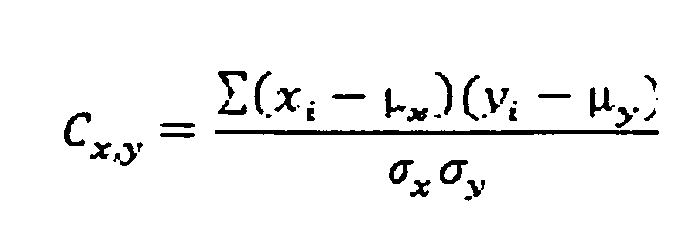
où :
Cx,yest un coefficient de corrélation ;
xiest une valeur dans la première partie de l'ensemble de valeurs détectées ; les valeurs
allant de 1 à n, n étant le nombre total de valeurs dans la première partie de l'ensemble
de valeurs détectées ;
yiest la valeur correspondant à la position de xi dans la première partie de l'ensemble de valeurs stockées ;
µxest la moyenne des valeurs dans la première partie de l'ensemble de valeurs détectées
;
µyest la moyenne des valeurs dans la première partie de l'ensemble de valeurs stockées
;
σxest l'écart-type des valeurs dans la première partie de l'ensemble de valeurs détectées
; et
σyest l'écart-type des valeurs dans la première partie de l'ensemble de valeurs stockées.
33. Appareil selon la revendication 32, dans lequel ledit circuit est opérationnel pour
générer un ensemble de valeurs détectées ayant une première partie comprenant des
valeurs de réflectance générées en réponse au rayonnement de chacun desdits types
d'émetteurs, et pour calculer une valeur représentative d'un niveau de corrélation
avec la première partie de chacun d'une septième pluralité d'ensembles de valeurs
stockées correspondant aux valeurs de réflectance de chacun desdits types d'émetteurs.
34. Appareil selon la revendication 32, dans lequel ledit circuit est opérationnel pour
générer un ensemble de valeurs détectées ayant une première partie comprenant des
valeurs de transmission générées en réponse au rayonnement de chacun desdits types
d'émetteurs et pour calculer une valeur représentative d'un niveau de corrélation
avec la première partie de chacun d'une septième pluralité d'ensembles de valeurs
stockées correspondant à des valeurs de transmission de chacun desdits types d'émetteurs.
35. Appareil selon la revendication 34, dans lequel lesdits ensembles de valeurs stockées
comprennent des valeurs de réflectance ou de transmission correspondant à chacun de
ladite pluralité de types de billets connus décalé dans la direction de billets à
partir dudit billet.
36. Appareil selon la revendication 34, dans lequel lesdits ensembles de valeurs stockées
comprennent des valeurs de transmission ou de réflectance correspondant à chacun de
ladite pluralité de types de billets connus décalé dans une direction transversale
à la direction de billets à partir dudit billet.
37. Appareil selon la revendication 1, dans lequel ladite source de rayonnement comprend
une deuxième pluralité d'émetteurs de rayonnement, lesdits émetteurs comprenant une
troisième pluralité de types d'émetteurs, dans lequel chaque type d'émetteurs génère
un rayonnement à une longueur d'onde différente de celle des autres types, et dans
lequel tous lesdits émetteurs dirigent le rayonnement vers une zone de test sur ledit
billet, et dans lequel au moins l'un desdits premier et deuxième détecteurs est positionné
de manière adjacente à ladite zone de test.
38. Appareil selon la revendication 37, dans lequel ledit circuit est opérationnel pour
générer un ensemble de valeurs détectées comprenant une première partie correspondant
à des valeurs de transmission ou de réflectance pour l'un desdits types d'émetteurs,
et dans lequel ledit circuit est opérationnel pour générer des ensembles de valeurs
stockées comprenant lesdites valeurs stockées, et dans lequel lesdits ensembles de
valeurs stockées comprennent chacun une première partie correspondante dans lequel
chaque dite première partie correspondante d'un ensemble de valeurs stockées correspond
aux dites valeurs de transmission ou de réflectance pour ledit type d'émetteurs et
un type de billets connu, et dans lequel ledit circuit est opérationnel pour calculer
ladite valeur représentative du niveau de corrélation entre ladite première partie
dudit ensemble de valeurs détectées et ladite première partie correspondante de chaque
ensemble de valeurs stockées.
39. Appareil selon la revendication 38, dans lequel ledit circuit est opérationnel pour
produire un ensemble de valeurs détectées comprenant une quatrième pluralité de parties,
chaque partie correspondant à des valeurs de réflectance ou de transmission de chacun
de ladite troisième pluralité de types d'émetteurs, et dans lequel ledit circuit est
opérationnel pour générer des ensembles de valeurs stockées, chaque dit ensemble de
valeurs stockées comprenant ladite quatrième pluralité de parties correspondantes
correspondant aux dites valeurs de transmission ou de réflectance pour chacun desdits
types d'émetteurs et un type de billets connu, et dans lequel ledit circuit calcule
ladite valeur représentative d'un niveau de corrélation pour chaque partie de l'ensemble
de valeurs détectées et chaque partie correspondante de chaque ensemble de valeurs
stockées.
40. Appareil selon la revendication 39, dans lequel le circuit est opérationnel pour calculer
ladite valeur représentative du niveau de corrélation entre l'ensemble de valeurs
détectées et chaque ensemble de valeurs stockées, en combinant des valeurs représentatives
du niveau de corrélation entre les parties correspondantes de l'ensemble de valeurs
détectées et de chaque ensemble de valeurs stockées.
41. Appareil selon la revendication 39, dans lequel ledit circuit est opérationnel pour
calculer une valeur représentative du niveau global de corrélation entre l'ensemble
de valeurs détectées et un ensemble de valeurs stockées en multipliant entre elles
des valeurs représentatives d'un niveau de corrélation des valeurs de réflectance
dans des parties correspondantes de l'ensemble de valeurs détectées et de l'ensemble
de valeurs stockées pour obtenir un produit de réflectance qui correspond à un niveau
global de corrélation pour la réflectance entre l'ensemble de valeurs détectées et
l'ensemble de valeurs stockées, dans lequel ledit circuit est en outre opérationnel
pour multiplier entre elles des valeurs représentatives du niveau de corrélation des
valeurs de transmission dans des parties correspondantes de l'ensemble de valeurs
détectées et de l'ensemble de valeurs stockées pour obtenir un produit de transmission
qui correspond à un niveau global de corrélation pour la transmission entre l'ensemble
de valeurs détectées et l'ensemble de valeurs stockées, et dans lequel ledit circuit
est en outre opérationnel pour produire la valeur représentative du niveau global
de corrélation entre l'ensemble de valeurs détectées et l'ensemble de valeurs stockées
en multipliant le produit de transmission par le produit de réflectance.
42. Appareil selon la revendication 1, dans lequel ledit billet a une position et dans
lequel lesdites valeurs stockées comprennent des données représentatives de modèles
de valeurs stockées correspondant à des valeurs de réflectance et de transmission
pour chacun de ladite pluralité de types de billets connus à ladite position de billet
et à des positions disposées à partir de ladite position de billet.
43. Appareil selon la revendication 42, dans lequel ledit billet s'étend généralement
dans un plan et dans lequel lesdits modèles correspondent aux dits types de billets
connus à partir de ladite position de billet dans une première direction dans ledit
plan.
44. Appareil selon la revendication 43, dans lequel lesdits modèles correspondent aux
dits types de billets connus décalés à partir de ladite position de billet dans une
direction transversale à ladite première direction.
45. Appareil selon la revendication 40, dans lequel ledit circuit est opérationnel pour
générer un signal correspondant à un ensemble de valeurs stockées fournissant la valeur
représentative du plus haut niveau de corrélation avec ledit ensemble de valeurs détectées,
de telle manière que ledit signal soit indicatif d'un type de billets particulier.
46. Appareil selon la revendication 45, dans lequel ledit circuit est opérationnel pour
comparer ladite valeur représentative dudit plus haut niveau de corrélation à une
valeur de seuil stockée, et dans lequel ledit circuit est opérationnel pour fournir
un deuxième signal lorsque ladite valeur représentative du plus haut niveau de corrélation
ne dépasse pas ladite valeur de seuil stockée.
47. Appareil selon la revendication 1, dans lequel lesdites valeurs stockées correspondent
à chacun de ladite pluralité de types de billets dans une deuxième pluralité de positions
angulaires.
48. Appareil selon la revendication 44, dans lequel lesdits ensembles de valeurs stockées
correspondent à chacun desdits types de billets connus décalés à partir de ladite
position de billet dans une deuxième pluralité de directions angulaires.
49. Appareil selon la revendication 1, dans lequel ledit appareil comprend des moyens
pour détecter un angle de déphasage dudit billet, et dans lequel ledit circuit est
opérationnel pour sélectionner lesdites valeurs stockées utilisées pour calculer ladite
valeur représentative du niveau de corrélation dans ledit magasin de données en réponse
au dit angle de déphasage détecté.
50. Appareil selon la revendication 27, dans lequel ledit circuit est opérationnel pour
déterminer un angle de déphasage dudit billet en réponse aux dits ensembles de détection
de zones détectant d'abord une propriété de transmission ou de réflectance dudit billet
à différents moments, et dans lequel lesdites valeurs stockées utilisées pour calculer
ladite valeur représentative d'un niveau de corrélation sont sélectionnées par ledit
circuit en réponse au dit angle de déphasage.
51. Appareil selon la revendication 50, dans lequel ledit angle de déphasage est calculé
par ledit circuit en réponse à une valeur de transmission ou de réflectance à partir
d'un premier type d'émetteurs dans un premier ensemble de détection de zones dépassant
une valeur de seuil, et ladite valeur de transmission ou de réflectance pour ledit
premier type d'émetteurs dans un deuxième ensemble de détection de zones transversalement
espacé dudit premier ensemble de détection de zones atteignant ladite valeur de seuil
à un moment ultérieur.
52. Appareil selon la revendication 51, dans lequel ledit circuit calcule ledit angle
de déphasage en fonction dudit moment, d'une distance séparant lesdits premier et
deuxième ensembles de détection de zones, ou d'une vitesse à laquelle ledit transport
déplace ledit billet.
53. Appareil selon la revendication 47, dans lequel ledit circuit est opérationnel pour
générer des ensembles de valeurs stockées, dans lequel ladite valeur représentative
d'un niveau de corrélation est calculée entre lesdites valeurs de réflectance et de
transmission et lesdits ensembles de valeurs stockées, et dans lequel ledit circuit
est opérationnel pour inclure sélectivement des valeurs stockées dudit magasin de
données dans ledit ensemble de valeurs stockées en réponse au dit angle de déphasage.
54. Appareil selon la revendication 53, dans lequel ledit magasin de données comprend
des données représentatives d'au moins un modèle correspondant à chacun de ladite
pluralité de types de billets connus, et dans lequel ledit modèle comprend des valeurs
correspondant à des valeurs de transmission et de réflectance pour ledit type de billets
correspondant à un angle de déphasage généralement nul, et dans lequel ledit circuit
génère ledit ensemble de valeurs stockées à partir dudit modèle en réponse au dit
angle de déphasage.
55. Appareil selon la revendication 54, dans lequel ledit magasin de données comprend
au moins un dit modèle pour chacun de ladite pluralité de types de billets connus,
dans lequel ledit modèle comprend des valeurs stockées correspondant aux dites valeurs
de réflectance et de transmission pour ledit type de billets à une troisième pluralité
de positions transversales.
56. Appareil selon la revendication 55, dans lequel ledit appareil comprend en outre un
transport pour déplacer relativement ledit billet dans une direction de billets par
rapport à ladite source de rayonnement et aux dits détecteurs, et dans lequel ledit
billet en déplacement relatif comprend une quatrième pluralité de zones de test, et
dans lequel chacune desdites zones de test est séparée de chaque zone de test adjacente
dans ladite direction de billets d'une distance d'espacement de zones, et dans lequel
chaque dit modèle comprend des valeurs stockées correspondant aux dites valeurs de
réflectance et de transmission pour chacun desdits types de billets connus par incrément
uniforme inférieur à ladite distance d'espacement de zones.
57. Appareil selon la revendication 56, dans lequel lesdits incréments sont généralement
d'un quart de ladite distance d'espacement de zones.
58. Appareil selon la revendication 56, dans lequel ledit magasin de données comprend
pour chacun de ladite pluralité de types de billets un modèle principal (70), et dans
lequel chaque dit modèle principal comprend une cinquième pluralité de sous-modèles
correspondant à un type de billets, et dans lequel chacun desdits modèles principaux
correspond au dit type de billets à un angle de déphasage nul, et dans lequel chacun
desdits sous-modèles dans l'un des modèles principaux correspond à des valeurs de
transmission et de réflectance pour ledit type de billets disposé à partir d'un sous-modèle
adjacent dans une direction transversale de ladite direction de billets, et dans lequel
ledit circuit est opérationnel pour inclure des valeurs dans lesdits ensembles de
valeurs stockées pour ledit type de billets à partir desdits sous-modèles dans le
modèle principal en réponse au dit angle de déphasage.
59. Appareil selon la revendication 1, dans lequel ledit circuit comprend un processeur
de signal numérique (136), et dans lequel ledit magasin de données comprend des données
représentatives d'au moins un modèle correspondant à un type de billets connu et ayant
lesdites données stockées dans celui-ci correspondant au dit type de billets dans
une deuxième pluralité de positions de billets, et dans lequel ledit processeur de
signal numérique dudit circuit accède aux dites valeurs stockées comprenant ledit
modèle.
60. Appareil selon la revendication 59, dans lequel ledit circuit comprend une troisième
pluralité de processeurs de signaux numériques, et dans lequel chacun desdits processeurs
de signaux numériques accède aux valeurs stockées dans les modèles associés à un processeur
de signal numérique particulier.
61. Appareil selon la revendication 60, dans lequel ledit circuit est opérationnel pour
calculer une valeur de corrélation correspondant au plus haut niveau de corrélation
entre lesdites valeurs de réflectance et de transmission détectées pour ledit billet
et les valeurs stockées dans chacun desdits modèles.
62. Appareil selon la revendication 61, dans lequel ledit circuit est en outre opérationnel
pour générer un signal représentatif de ladite plus haute valeur de corrélation parmi
tous lesdits modèles, de telle manière que ledit signal indique que le billet détecté
a le plus haut niveau de corrélation avec les valeurs stockées pour un type de billets
particulier.
63. Appareil selon la revendication 61, dans lequel ladite valeur de corrélation est une
fonction d'une valeur de corrélation de transmission et d'une valeur de corrélation
de réflectance, dans lequel ladite fonction est calculée par ledit circuit, et dans
lequel ladite valeur de corrélation de transmission est calculée par ledit circuit
et est indicative d'un niveau de corrélation entre lesdites valeurs de transmission
détectées et les valeurs stockées dans ledit modèle correspondant aux valeurs de transmission,
et dans lequel ladite valeur de corrélation de réflectance est calculée par ledit
circuit et est indicative d'un niveau de corrélation entre lesdites valeurs de réflectance
détectées et lesdites valeurs stockées dans ledit modèle correspondant aux valeurs
de réflectance.
64. Appareil selon la revendication 63, dans lequel ladite source de rayonnement comprend
une quatrième pluralité de types d'émetteurs, dans lequel chaque type d'émetteur émet
un rayonnement à une longueur d'onde généralement différente de celle des autres types
d'émetteurs, et dans lequel ledit circuit est opérationnel pour calculer ladite valeur
de corrélation de transmission en tant que combinaison de valeurs de corrélation de
types d'émetteurs calculées représentatives de niveaux de corrélation entre les valeurs
de transmission dudit billet pour chacun desdits types d'émetteurs, et des valeurs
stockées dans lesdits modèles correspondant à chacun desdits types d'émetteurs.
65. Appareil selon la revendication 63, dans lequel ladite source de rayonnement comprend
une quatrième pluralité de types d'émetteurs et dans lequel ledit circuit est opérationnel
pour calculer ladite valeur de corrélation de réflectance en réponse à un niveau de
corrélation entre lesdites valeurs de réflectance dudit billet pour chacun desdits
types d'émetteurs, et les valeurs stockées dans lesdits modèles correspondant à chacun
desdits types d'émetteurs.
66. Appareil selon la revendication 64, dans lequel ledit circuit est opérationnel pour
générer des valeurs de réflectance et de transmission pour une cinquième pluralité
de zones de test généralement alignées linéairement, de telle manière que lesdites
zones de test s'étendent dans une ligne sur ledit billet, et dans lequel lesdites
valeurs de corrélation de réflectance et de transmission de billet sont calculées
par ledit circuit pour toutes les zones de test dans ladite ligne pour chacun desdits
types d'émetteurs en calculant une valeur représentative d'un niveau de corrélation
avec les valeurs stockées dans chacun desdits modèles correspondant à ladite ligne
et au dit type d'émetteurs.
67. Appareil selon la revendication 66, dans lequel ledit circuit est opérationnel pour
générer des valeurs de réflectance et de transmission correspondant à une sixième
pluralité de lignes de zones de test, et dans lequel lesdites valeurs de corrélation
de transmission et de réflectance sont calculées par ledit circuit à partir des valeurs
stockées dans chaque dit modèle correspondant à chaque dite ligne de zones de test
et à chaque type d'émetteurs.
68. Procédé pour déterminer un type associé à un billet, comprenant les étapes consistant
à :
illuminer une zone de test (34) sur ledit billet (30) avec une source de rayonnement
; détecter avec un premier détecteur (20) le rayonnement réfléchi de ladite zone de
test et générer un premier signal en réponse au dit rayonnement réfléchi détecté ;
détecter avec un deuxième détecteur (22) le rayonnement transmis à travers ladite
zone de test et générer un deuxième signal en réponse au dit rayonnement transmis
détecté ;
calculer avec un circuit (24) une valeur représentative d'un niveau de corrélation
entre lesdits premier et deuxième signaux et les valeurs stockées dans un magasin
de données (26) correspondant aux propriétés de transmission et de réflectance adjacentes
à ladite zone de test pour une pluralité de types de billets connus.
69. Procédé selon la revendication 68, dans lequel lesdites valeurs stockées sont agencées
dans des ensembles de valeurs stockées, chaque dit ensemble de valeurs stockées correspondant
à l'un desdits types de billets connus, et comprenant en outre l'étape consistant
à fournir un signal indicatif du type de billets connu ayant la plus grande valeur
représentative du niveau de corrélation avec lesdits premier et deuxième signaux.
70. Procédé selon la revendication 68, dans lequel ladite étape d'illumination comprend
l'illumination de ladite zone de test séquentiellement avec une deuxième pluralité
de types d'émetteurs de rayonnement (32), chaque type d'émetteurs émettant un rayonnement
à une longueur d'onde généralement différente de celle des autres types d'émetteurs.
71. Procédé selon la revendication 70, dans lequel à ladite première étape de détection,
ladite deuxième pluralité de premiers signaux sont générés, chacun correspondant à
un type d'émetteurs, et dans lequel, à ladite étape de calcul, il est calculé une
première valeur de corrélation représentative d'un niveau de corrélation entre chacun
desdits premiers signaux pour ledit billet et les premières valeurs stockées correspondant
à la réflectance à partir dudit type d'émetteurs pour chacun de ladite pluralité de
types de billets connus.
72. Procédé selon la revendication 71, dans lequel, à ladite deuxième étape de détection,
ladite deuxième pluralité de deuxièmes signaux sont générés, chacun correspondant
à un type d'émetteurs, et dans lequel, à ladite étape de calcul, il est calculé une
deuxième valeur de corrélation représentative d'un niveau de corrélation entre chacun
desdits deuxième signaux pour ledit billet et les deuxièmes valeurs stockées correspondant
à la transmission dudit type d'émetteurs correspondant à travers chacun de ladite
pluralité de types de billets connus.
73. Procédé selon la revendication 72, dans lequel ladite étape de calcul comprend le
calcul desdites première et deuxième valeurs de corrélation pour ledit billet et chacun
de ladite pluralité de types de billets connus, ladite valeur représentative d'un
niveau de corrélation étant calculée en fonction desdites première et deuxième valeurs
de corrélation.
74. Procédé selon la revendication 72 et comprenant en outre l'étape consistant à effectuer
lesdites première et deuxième étapes de détection de manière adjacente à une troisième
pluralité de zones de test sur ledit billet, lesdites zones de test étant agencées
dans une grille, et dans lequel lesdites première et deuxième valeurs stockées sont
représentatives des propriétés de transmission et de réflectance adjacentes à chacune
desdites zones de test dans ladite grille pour chacun desdits types de billets connus,
et lesdites valeurs sont stockées sous forme de données représentatives d'un modèle
dans ledit magasin de données, et dans lequel ladite étape de calcul comprend la génération
avec ledit circuit d'un ensemble de valeurs stockées comprenant des valeurs de chaque
modèle, et le calcul de ladite valeur représentative d'un niveau de corrélation en
fonction des valeurs correspondant aux dits premier et deuxième signaux pour chacune
desdites zones de test sur ledit billet et desdites première et deuxième valeurs dans
chacun desdits ensembles de valeurs stockées.
75. Procédé selon la revendication 68, dans lequel ladite étape d'illumination comprend
l'illumination d'une deuxième pluralité de zones de test sur une grille sur ledit
billet, chaque zone de test étant séquentiellement illuminée par une troisième pluralité
de types d'émetteurs de rayonnement, chaque type d'émetteurs de rayonnement produisant
un rayonnement à une longueur d'onde généralement différente de celle des autres types
d'émetteurs, et dans lequel lesdites première et deuxième étapes de détection comprennent
la génération desdits premier et deuxième signaux à chacune de ladite deuxième pluralité
de zones de test pour chacun de ladite troisième pluralité d'émetteurs, et dans lequel
ladite étape de calcul comprend la génération avec ledit circuit des valeurs de réflectance
et de transmission en réponse respectivement à chacun desdits premiers signaux et
desdits deuxièmes signaux, et dans lequel lesdites valeurs de réflectance et de transmission
sont placées dans un ensemble de valeurs détectées, et dans lequel ladite étape de
calcul comprend en outre la génération avec ledit circuit des ensembles de valeurs
stockées comprenant des valeurs stockées dudit magasin de données, et dans lequel
lesdits ensembles de valeurs stockées correspondent à des valeurs de transmission
et de réflectance pour chacun de ladite pluralité de types de billets connus, et dans
lequel ladite valeur représentative d'un niveau de corrélation est calculée pour ledit
ensemble de valeurs détectées et chacun desdits ensembles de valeurs stockées.
76. Procédé selon la revendication 75 et avant ladite étape d'illumination comprenant
en outre l'étape consistant à stocker dans ledit magasin de données les valeurs stockées
correspondant aux dites valeurs de transmission et de réflectance pour chaque type
d'émetteurs adjacent à chaque zone de test pour chacun desdits types de billets connus
disposés dans une quatrième pluralité de positions spatiales.
77. Procédé selon la revendication 68 et avant ladite étape de calcul comprenant en outre
l'étape consistant à déterminer un angle de déphasage dudit billet par rapport aux
dits premier et deuxième signaux, et, à laquelle étape de calcul, lesdites valeurs
stockées sont sélectionnées dans ledit magasin de données en réponse au dit angle
de déphasage, et dans lequel ladite valeur représentative d'un niveau de corrélation
est calculée par ledit circuit en utilisant lesdites valeurs sélectionnées.
REFERENCES CITED IN THE DESCRIPTION
This list of references cited by the applicant is for the reader's convenience only.
It does not form part of the European patent document. Even though great care has
been taken in compiling the references, errors or omissions cannot be excluded and
the EPO disclaims all liability in this regard.
Patent documents cited in the description