(57) The invention concerns a method for splicing ends of a first and second current carrying
cables (50, 52), each cable (50, 52) comprising of a fiber containing reinforced plastic
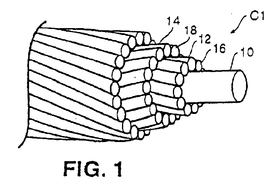
composite core (22) formed from a plurality of sections (20, 20a, 20b, 20c, 20d) and
an outer highly conductive current carrying sheath (64, 66). The ends of the individual
sections of the first cable (50) to be spliced are cut at staggered lengths relative
to one another so that each section (20a, 20c) of the core (22) of the first cable
(50) has a length different from the length of any other section of the first cable
(50). The ends of the individual sections of the second cable (52) to be spliced are
cut at staggered lengths relative to one another so that each section (20b, 20d) of
the core (22) of the second cable (52) has a length different from the length of any
other section of the second cable (52). The ends of the first cable sections (20a,
20c) are matched with corresponding ends of the second cable (52) so that the ends
of the first cable sections (20a, 20c) will abut against corresponding ends of the
second cable sections (20b, 20d) when all of the individual sections (20a, 20b, 20c,
20d) are abutted. Spliced ends of the individual cable sections (20a, 20b, 20c, 20d)
as abutted are heated to cause a resin impregnated in the cables (50, 52) to partially
liquefy and effectively flow around corresponding ends. The resin is allowed to cool
and thereby permanently to bond the core sections (20a, 20c) of the first cable (50)
to the core sections (20b, 20d) of the second cable (52). The invention concerns also
a method for increasing the current carried between two high voltage conductor support
towers. A first high voltage carrying cable suspended between the towers is removed,
wherein said first cable has a steel core and a conductor surrounding the core, and
the conductor comprises an outer surface diameter. Said first high voltage carrying
cable is replaced with a second cable on the towers such that the second cable is
suspended between the towers, wherein the second cable comprises a composite core
surrounded by a conductor wherein the conductor of the second cable has an outer surface
diameter that is not greater than the outer surface diameter of the conductor of the
first cable and wherein the second cable carries more current than the first cable.
|
|
