| (19) |
 |
|
(11) |
EP 1 739 336 B1 |
| (12) |
EUROPEAN PATENT SPECIFICATION |
| (45) |
Mention of the grant of the patent: |
|
29.07.2009 Bulletin 2009/31 |
| (22) |
Date of filing: 27.06.2006 |
|
| (51) |
International Patent Classification (IPC):
|
|
| (54) |
Fluid coupling cap
Kappe für eine Flüssigkeitskupplung
Capuchon pour un raccord de fluide
|
| (84) |
Designated Contracting States: |
|
DE ES FR GB IT |
| (30) |
Priority: |
30.06.2005 US 170810
|
| (43) |
Date of publication of application: |
|
03.01.2007 Bulletin 2007/01 |
| (73) |
Proprietor: Eaton Corporation |
|
Cleveland, Ohio 44114-2584 (US) |
|
| (72) |
Inventor: |
|
- Wells, Michael Paul
Bowling Green
Ohio 43402 (US)
|
| (74) |
Representative: Rüger, Barthelt & Abel
Patentanwälte |
|
Postfach 10 04 61
73704 Esslingen a.N.
73704 Esslingen a.N. (DE) |
| (56) |
References cited: :
EP-A1- 0 621 053
|
DE-U1- 7 634 217
|
|
| |
|
|
|
|
| |
|
| Note: Within nine months from the publication of the mention of the grant of the European
patent, any person may give notice to the European Patent Office of opposition to
the European patent
granted. Notice of opposition shall be filed in a written reasoned statement. It shall
not be deemed to
have been filed until the opposition fee has been paid. (Art. 99(1) European Patent
Convention).
|
BACKGROUND OF THE INVENTION
Field of the Invention
[0001] The present invention relates generally to fluid couplings and to a dust and impact
protection cap for a fluid coupling.
Description of the Related Art
[0002] There are many applications where a fluid power system requires that a connection
be made between a hose assembly and an apparatus, such as a tank, reservoir, pump,
motor or valve. In one arrangement, a male fluid coupling is connected to the apparatus
and functions as a port to which a hose-secured female fluid coupling may be connected.
When disconnected from the female fluid coupling, the male fluid coupling is covered
with a cap to protect it from dust, dirt and other debris. Since male fluid couplings
may protrude from the apparatus, caps also protect the male fluid coupling from damage
due to impacts with other objects.
DE 7634217 U1 discloses a cap for a fluid coupling comprising a stem member adapted for insertion
into the fluid coupling and a cover member connected to the stem member and adapted
to be screwed onto the fluid coupling. The cover member includes an internal cavity
sized to receive the fluid coupling such that the fluid coupling can be positioned
between the stem member and the cover member.
[0003] Among other things, it is improvement of this cap that is the subject of the invention
set forth herein
and defined by the features of claim 1.
SUMMARY OF THE INVENTION
[0004] A cap for a fluid coupling is provided that includes a stem member adapted for insertion
into the fluid coupling and a cover member connected to the stem member. The cover
member includes an internal cavity sized to receive the fluid coupling such that the
fluid coupling is positioned between the stem member and the cover member. The internal
cavity is defined by a wall having at least one of a longitudinally extending groove
and a longitudinally extending protrusion. A fluid coupling assembly that includes
a cap according to an embodiment of the present invention is also provided. Other
aspects of the invention will be apparent to those skilled in the art after review
of the drawings and detailed description provided below.
BRIEF DESCRIPTION OF THE DRAWINGS
[0005] Embodiments of the invention will now be described, by way of example, with reference
to the accompanying drawings, wherein:
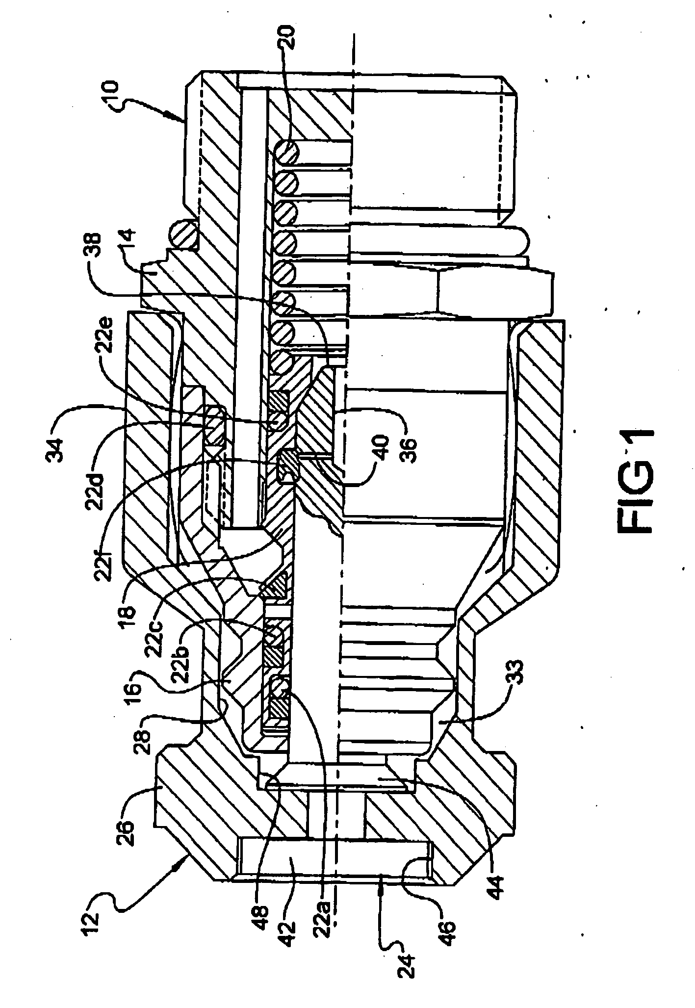
FIG. 1 is a partial cross-sectional view of a fluid coupling and a cap according to
an embodiment of the present invention;
FIG. 2 is bottom view of a cover member for use in the cap of FIG. 1; and
FIG. 3 is a partial cross-sectional view of the cover member shown in FIG. 2.
DETAILED DESCRIPTION
[0006] Referring to FIG. 1, a fluid coupling assembly is shown that includes an exemplary
fluid coupling 10 and a cap 12 according to an embodiment of the present invention.
By way of reference, fluid coupling 10 is a "male" fluid coupling that includes an
adapter 14 for connecting fluid coupling 10 to an apparatus, such as a pump, motor
or valve, and a body member 16 that secures a valve 18 for movement within adapter
14 against the biasing force of a spring 20. Fluid coupling 10 includes various seals
22a-22f that function to inhibit leakage of fluid when fluid coupling 10 is connected
to cap 12 or a separate mating fluid coupling (not shown). Fluid coupling 10 may be
used to provide a port in an apparatus for connecting a fluid conveying component,
such as, for example, a hydraulic hose having a mating fluid coupling. When not connected
to a mating fluid coupling, cap 12 covers fluid coupling 10 to inhibit the ingression
of dust, dirt and other debris into fluid coupling 10, while providing protection
against impacts.
[0007] In the embodiment shown in FIG. 1, cap 12 includes a generally cylindrical stem member
24 adapted for insertion into fluid coupling 10, and a cover member 26 connected to
stem member 24, Cover member 26 includes an internal cavity 28 sized to receive body
16 of fluid coupling 10 such that fluid coupling 10 is positioned between stem member
24 and cover member 26.
[0008] In an embodiment shown in FIGS. 2 and 3, internal cavity 28 of cover member 26 is
defined by a wall 30 having at least one longitudinally extending groove 32. At least
a portion of wall 30 engages an outer surface of fluid coupling 10 to create a pocket
33 (
see, e.g., FIG. 1) between cover member 26 and body 16 of fluid coupling 10. The longitudinally
extending groove 32 defines a fluid flow-path between pocket 33 and an exterior 34
of cap 12 to vent any fluid contained with pocket 32. For example, as cap 12 is placed
on fluid coupling 10, air trapped between cap 12 and fluid coupling 10 may be vented
through grooves 32 to prevent cap 12 from being forced off after assembly due to trapped
air pressure. Additionally, any fluid that leaks past the interface of stem member
24 and fluid coupling 10 during connection may be vented before pressurized fluid
can accumulate in pocket 33 and force cap 12 off of fluid coupling 10. As shown in
FIGS. 2 and 3, wall 30 may include a plurality of longitudinally extending grooves
32 to further vent fluid from pocket 33.
[0009] Alternatively, inner surface of groove 32 may be deemed a wall having at least one
longitudinally extending projection (denoted, for example, by reference numeral 30
in FIG. 2). When so defined, the longitudinally extending projection engages an outer
surface of fluid coupling 10 to create pocket 33 between the wall of cover member
26 and fluid coupling 10. Like groove 32, the longitudinally extending projection
helps define a fluid flow-path between pocket 33 and exterior 34 of cap 12, Cover
member 26 may include a plurality of longitudinally extending projections to further
facilitate the transfer of fluid from pocket 33.
[0010] In addition to defining a fluid flow-path, the longitudinally extending grooves and
projections reduce the surface area of cover member 26 in contact with fluid coupling
10. At relatively low temperatures, cap 12 may shrink around fluid coupling 10 rendering
cap 12 difficult to remove. By reducing the surface area of cover member 26 in contact
with fluid coupling 10, the forces resisting removal of cap 12 are also reduced.
[0011] Referring again to FIG. 1, stem member 24 may include an opening 36 adjacent a distal
end 38. A duct 40 is positioned to provide opening 36 in fluid communication with
an exterior of stem member 24. Duct 40 provides controlled venting of trapped fluid
pressure between seals 22a and 22f when stem member 24 is being removed from fluid
coupling 10. Stem member 24 may also include first and second flanges 42 and 44, which
may be received within corresponding recesses 46 and 48 in cover member 26 to secure
cover member 26 to stem member 24.
[0012] As shown in FIGS. 2 and 3, cover member 26 may include a tethering member 50 adapted
to secure cap 12 to fluid coupling 10 or apparatus structure (not shown) adjacent
cap 12. In an embodiment, tethering member 50 includes a flexible eyelet 52 having
an aperture 54 and an elongated channel 56 that extends from aperture 54 and allows
eyelet 52 to deform around fluid coupling 10 or the adjacent apparatus structure when
fluid coupling 10 or the adjacent apparatus structure is inserted through eyelet 52.
Cover member 26 may be made of the same flexible material as tethering member 50,
including, without limitation, rubber and plastic.
1. A cap (12) for a fluid coupling (10), comprising:
a stem member (24) adapted for insertion into the fluid coupling (10); and
a cover member (26) connected to the stem member (24) and including an internal cavity
(28) sized to receive the fluid coupling (10) such that the fluid coupling (10) is
positioned between the stem member (24) and the cover member (26), characterized in that the internal cavity (28) is defined by a wall (30) having at least one of a longitudinally
extending groove (32) and a longitudinally extending protrusion, extending to an end
face of the cover member.
2. The cap (12) of claim 1, wherein the wall (30) includes a plurality of longitudinally
extending grooves (32).
3. The cap (12) of claim 1, wherein the wall (30) includes a plurality of longitudinally
extending projections (30).
4. The cap (12) of claim 1, wherein a portion of the wall (30) engages an outer surface
of the fluid coupling to create a pocket (33) between the cover member (26) and the
fluid coupling (10), and wherein the longitudinally extending groove (32) defines
a fluid flow-path between the pocket (33) and an exterior (34) of the cap (12).
5. The cap (12) of claim 1, wherein the projection (30) engages an outer surface of the
fluid coupling (10) to create a pocket (33) between the cover member (26) and the
fluid coupling (10), and wherein the longitudinally extending projection (30) defines
a fluid flow-path between the pocket (33) and an exterior (34) of the cap (12).
6. The cap (12) of claim 1, wherein the stem member (24) includes an opening (36) adjacent
a distal end (38) thereof.
7. The cap (12) of claim 6, wherein a duct (40) is positioned to provide the opening
(36) in fluid communication with an exterior of the stem member (24) to allow controlled
venting of trapped fluid pressure when the stem member (24) is being removed from
the fluid coupling (10).
8. The cap (12) of claim 1, wherein the stem member includes first and second flanges
(42, 44) received within corresponding recesses (46, 48) in the cover member (26)
to secure the cover member (26) to the stem member (24).
9. The cap (12) of claim 1, further including a tethering member (50) adapted to secure
the cap (12) to the fluid coupling (10).
10. The cap (12) of claim 1, wherein the cover member (26)is flexible.
11. A fluid coupling assembly, comprising:
a fluid coupling (10); and
a cap (12) according to claim 1.
12. The fluid coupling assembly of claim 11, wherein the wall (30) includes a plurality
of longitudinally extending grooves (32).
13. The fluid coupling assembly of claim 11, wherein the wall (30) includes a plurality
of longitudinally extending projections (30).
14. The fluid coupling assembly of claim 11, wherein a portion of the wall (30) engages
an outer surface of the fluid coupling (10) to create a pocket (33) between the cover
member (26) and the fluid coupling (10), and wherein the longitudinally extending
groove (32) defines a fluid flow-path between the pocket (33) and an exterior (34)
of the cap (12).
15. The fluid coupling assembly of claim 11, wherein the projection (30) engages an outer
surface of the fluid coupling (10) to create a pocket (33) between the cover member
(26) and the fluid coupling (10), and wherein the longitudinally extending projection
(30) defines a fluid flow-path between the pocket (33) and an exterior (34) of the
cap (12).
16. The fluid coupling assembly of claim 11, wherein the stem member (24) includes an
opening (36) adjacent a distal end (38) thereof.
17. The fluid coupling assembly of claim 16, wherein a duct (40) is positioned to provide
the opening (36) in fluid communication with an exterior of the stem member (24) to
allow controlled venting of trapped fluid pressure when the stem member (24) is being
removed from the fluid coupling (10).
18. The fluid coupling assembly of claim 11, wherein the stem member (24) includes first
and second flanges (42, 44) received within corresponding recesses (46, 48) in the
cover member (26) to secure the cover member (26) to the stem member (24).
19. The fluid coupling assembly of claim 11, further including a tethering member (50)
adapted to secure the cap (12) to the fluid coupling (10).
20. The fluid coupling assembly of claim 11, wherein the cover member (26) is flexible.
1. Kappe (12) für eine Fluidkupplung (10), die aufweist:
ein Schaftelement (24), das zur Einführung in die Fluidkupplung (10) eingerichtet
ist; und
ein Abdeckelement (26), das mit dem Schaftelement (24) verbunden ist und einen inneren
Hohlraum (28) enthält, der bemessen ist, um die Fluidkupplung (10) derart aufzunehmen,
dass die Fluidkupplung (10) zwischen dem Schaftelement (24) und dem Abdeckelement
(26) positioniert ist, dadurch gekennzeichnet, dass der innere Hohlraum (28) durch eine Wand (30) definiert ist, die wenigstens entweder
eine in Längsrichtung verlaufende Nut (32) und/oder einen in Längsrichtung verlaufenden
Vorsprung aufweist, die bzw. der sich zu einer Stirnfläche des Abdeckelementes erstreckt.
2. Kappe (12) nach Anspruch 1, wobei die Wand (30) mehrere in Längsrichtung verlaufende
Nuten (32) enthält.
3. Kappe (12) nach Anspruch 1, wobei die Wand (30) mehrere in Längsrichtung verlaufende
Vorsprünge (30) enthält.
4. Kappe (12) nach Anspruch 1, wobei ein Abschnitt der Wand (30) mit einer Außenfläche
der Fluidkupplung verbunden ist, um zwischen dem Abdeckelement (26) und der Fluidkupplung
(10) eine Tasche (33) zu schaffen, und wobei die in Längsrichtung verlaufende Nut
(32) einen Fluidströmungspfad zwischen der Tasche (33) und einer Außenseite (34) der
Kappe (12) definiert.
5. Kappe (12) nach Anspruch 1, wobei der Vorsprung (30) mit einer Außenfläche der Fluidkupplung
(10) verbunden ist, um eine Tasche (33) zwischen dem Abdeckelement (26) und der Fluidkupplung
(10) zu schaffen, und wobei der in Längsrichtung verlaufende Vorsprung (30) einen
Fluidströmungspfad zwischen der Tasche (33) und einer Außenseite (34) der Kappe (12)
definiert.
6. Kappe (12) nach Anspruch 1, wobei das Schaftelement (24) eine Öffnung (36) benachbart
zu seinem distalen Ende (38) enthält.
7. Kappe (12) nach Anspruch 6, wobei ein Kanal (40) positioniert ist, um eine Fluidverbindung
der Öffnung (36) mit einer Außenseite des Schaftelementes (24) zu schaffen, um eine
kontrollierte Entlastung des Drucks von eingefangenem Fluid zu ermöglichen, wenn das
Schaftelement (24) von der Fluidkupplung (10) abgenommen wird.
8. Kappe (12) nach Anspruch 1, wobei das Schaftelement einen ersten und einen zweiten
Flansch (42, 44) enthält, die in zugehörigen Ausnehmungen (46, 48) in dem Abdeckelement
(26) aufgenommen sind, um das Abdeckelement (26) an dem Schaftelement (24) zu sichern.
9. Kappe (12) nach Anspruch 1, die ferner ein Anbindeelement (50) enthält, das eingerichtet
ist, um die Kappe (12) an der Fluidkupplung (10) zu sichern.
10. Kappe (12) nach Anspruch 1, wobei das Abdeckelement (26) elastisch ist.
11. Fluidkupplunganordnung, die aufweist:
eine Fluidkupplung (10); und
eine Kappe (12) gemäß Anspruch 1.
12. Fluidkupplungsanordnung nach Anspruch 11, wobei die Wand (30) mehrere in Längsrichtung
verlaufende Nuten (32) enthält.
13. Fluidkupplungsanordnung nach Anspruch 11, wobei die Wand (30) mehrere in Längsrichtung
verlaufende Vorsprünge (30) enthält.
14. Fluidkupplungsanordnung nach Anspruch 11, wobei ein Abschnitt der Wand (30) mit einer
Außenfläche der Fluidkupplung (10) verbunden ist, um eine Tasche (33) zwischen dem
Abdeckelement (26) und der Fluidkupplung (10) zu schaffen, und wobei die in Längsrichtung
verlaufende Nut (32) einen Fluidströmungspfad zwischen der Tasche (33) und einer Außenseite
(34) der Kappe (12) definiert.
15. Fluidkupplungsanordnung nach Anspruch 11, wobei der Vorsprung (30) mit einer Außenfläche
der Fluidkupplung (10) verbunden ist, um eine Tasche (33) zwischen dem Abdeckelement
(26) und der Fluidkupplung (10) zu schaffen, und wobei der in Längsrichtung verlaufende
Vorsprung (30) einen Fluidströmungspfad zwischen der Tasche (33) und einer Außenseite
(34) der Kappe (12) definiert.
16. Fluidkupplungsanordnung nach Anspruch 11, wobei das Schaftelement (24) eine Öffnung
(36) benachbart zu seinem distalen Ende (38) enthält.
17. Fluidkupplungsanordnung nach Anspruch 16, wobei ein Kanal (40) positioniert ist, um
die Öffnung (36) in Strömungsverbindung mit einer Außenseite des Schaftelementes (24)
zu bringen, um eine kontrollierte Entlastung von Druck von eingefangenem Fluid zu
ermöglichen, wenn das Schaftelement (24) von der Fluidkupplung (10) abgenommen wird.
18. Fluidkupplungsanordnung nach Anspruch 11, wobei das Schaftelement (24) einen ersten
und einen zweiten Flansch (42, 44) enthält, die in zugehörigen Ausnehmungen (46, 48)
in dem Abdeckelement (26) aufgenommen sind, um das Abdeckelement (26) an dem Schaftelement
(24) zu sichern.
19. Fluidkupplungsanordnung nach Anspruch 11, die ferner ein Anbindeelement (50) enthält,
das eingerichtet ist, um die Kappe (12) an der Fluidkupplung (10) zu sichern.
20. Fluidkupplungsanordnung nach Anspruch 11, wobei das Abdeckelement (26) elastisch ist.
1. Capuchon (12) pour un raccord fluidique (10), comprenant :
un élément de tige (24) adapté pour l'insertion dans le raccord fluidique (10); et
un élément de couvercle (26) relié à l'élément de tige (24) et comprenant une cavité
interne (28) dimensionnée de manière à recevoir le raccord fluidique (10) de sorte
que le raccord fluidique (10) soit positionné entre l'élément de tige (24) et l'élément
de couvercle (26), caractérisé en ce que la cavité interne (28) est définie par une paroi (30) ayant au moins l'une d'une
rainure (32) se déployant longitudinalement et une protubérance se déployant longitudinalement,
s'étendant vers une face extrême de l'élément de couvercle.
2. Capuchon (12) de la revendication 1, dans lequel la paroi (30) comprend plusieurs
rainures (32) se déployant longitudinalement.
3. Capuchon (12) de la revendication 1, dans lequel la paroi (30) comprend plusieurs
projections (30) se déployant longitudinalement.
4. Capuchon (12) de la revendication 1, dans lequel une partie de la paroi (30) engage
une surface externe du raccord fluidique afin de créer une poche (33) entre l'élément
de couvercle (26) et le raccord fluidique (10), et où la rainure (32) se déployant
longitudinalement définit un chemin d'écoulement fluidique entre la poche (33) et
la partie externe (34) du capuchon (12).
5. Capuchon (12) de la revendication 1, dans lequel la projection (30) engage une surface
externe du raccord fluidique (10) pour créer une poche (33) entre l'élément de couvercle
(26) et le raccord fluidique (10), et où la projection (30) se déployant longitudinalement
définit un chemin d'écoulement fluidique entre la poche (33) et la partie externe
(34) du capuchon (12).
6. Capuchon (12) de la revendication 1, dans lequel l'élément de tige (24) comprend une
ouverture (36) adjacente à une extrémité distale (38) de celui-ci.
7. Capuchon (12) de la revendication 6, dans lequel un conduit (40) est positionné afin
de placer l'ouverture (36) en communication fluidique avec une partie externe de l'élément
de tige (24) pour permettre une ventilation régulée de la pression fluidique emprisonnée
lorsque l'élément de tige (24) est retiré du raccord fluidique (10).
8. Capuchon (12) de la revendication 1, dans lequel l'élément de tige comporte une première
et une deuxième brides (42, 44) reçues dans des évidements (46, 48) correspondants
dans l'élément de couvercle (26) afin de fixer l'élément de couvercle (26) à l'élément
de tige (24).
9. Capuchon (12) de la revendication 1, comprenant en plus un élément de fixation (50)
adapté pour fixer le capuchon (12) au raccord fluidique (10).
10. Capuchon (12) de la revendication 1, dans lequel l'élément de couvercle (26) est souple.
11. Ensemble de raccord fluidique, comprenant :
un raccord fluidique (10); et
un capuchon (12) selon la revendication 1.
12. Ensemble de raccord fluidique de la revendication 11, dans lequel la paroi (30) comporte
plusieurs rainures (32) se déployant longitudinalement.
13. Ensemble de raccord fluidique de la revendication 11, dans lequel la paroi (30) comporte
plusieurs projections (30) se déployant longitudinalement.
14. Ensemble de raccord fluidique de la revendication 11, dans lequel une partie de la
paroi (30) engage une surface externe du raccord fluidique (10) pour créer une poche
(33) entre l'élément de couvercle (26) et le raccord fluidique (10), et où la rainure
(32) se déployant longitudinalement définit un chemin d'écoulement fluidique entre
la poche (33) et la partie externe (34) du capuchon (12).
15. Ensemble de raccord fluidique de la revendication 11, dans lequel la projection (30)
engage une surface externe du raccord fluidique (10) pour créer une poche (33) entre
l'élément de couvercle (26) et le raccord fluidique (10), et où la projection (30)
se déployant longitudinalement définit un chemin d'écoulement fluidique entre la poche
(33) et la partie externe (34) du capuchon (12).
16. Ensemble de raccord fluidique de la revendication 11, dans lequel l'élément de tige
(24) comprend une ouverture (36) adjacente à une extrémité distale (38) de celui-ci.
17. Ensemble de raccord fluidique de la revendication 16, dans lequel un conduit (40)
est positionné pour placer l'ouverture (36) en communication fluidique avec la partie
externe de l'élément de tige (24) afin de permettre une ventilation régulée de la
pression fluidique emprisonnée lorsque l'élément de tige (24) est retiré du raccord
fluidique (10).
18. Ensemble de raccord fluidique de la revendication 11, dans lequel l'élément de tige
(24) comprend une première et une deuxième brides (42, 44) reçues dans des évidements
(46, 48) correspondants dans l'élément de couvercle (26) afin de fixer l'élément de
couvercle (26) à l'élément de tige (24).
19. Ensemble de raccord fluidique de la revendication 11, comprenant en plus un élément
de fixation (50) adapté pour fixer le capuchon (12) au raccord fluidique (10).
20. Ensemble de raccord fluidique de la revendication 11, dans lequel l'élément de couvercle
(26) est souple.

REFERENCES CITED IN THE DESCRIPTION
This list of references cited by the applicant is for the reader's convenience only.
It does not form part of the European patent document. Even though great care has
been taken in compiling the references, errors or omissions cannot be excluded and
the EPO disclaims all liability in this regard.
Patent documents cited in the description