| (19) |
 |
|
(11) |
EP 1 940 676 B1 |
| (12) |
EUROPEAN PATENT SPECIFICATION |
| (45) |
Mention of the grant of the patent: |
|
29.07.2009 Bulletin 2009/31 |
| (22) |
Date of filing: 20.09.2006 |
|
| (51) |
International Patent Classification (IPC):
|
| (86) |
International application number: |
|
PCT/IB2006/053391 |
| (87) |
International publication number: |
|
WO 2007/034422 (29.03.2007 Gazette 2007/13) |
|
| (54) |
SADDLE WITH QUICK-CONNECTION MEANS TO ATTACH BICYCLE ACCESSORIES
SATTEL MIT SCHNELLVERBINDUNGSMITTEL ZUM ANBRINGEN VON FAHRRADZUBEHÖR
SELLE AVEC MOYENS DE RACCORDEMENT RAPIDE POUR MONTAGE D'ACCESSOIRES DE BICYCLETTE
|
| (84) |
Designated Contracting States: |
|
AT BE BG CH CY CZ DE DK EE ES FI FR GB GR HU IE IS IT LI LT LU LV MC NL PL PT RO SE
SI SK TR |
| (30) |
Priority: |
20.09.2005 IT VI20050242
|
| (43) |
Date of publication of application: |
|
09.07.2008 Bulletin 2008/28 |
| (73) |
Proprietor: SELLE ROYAL S.P.A. |
|
36050 Pozzoleone (Vicenza) (IT) |
|
| (72) |
Inventor: |
|
- BIGOLIN, Barbara
I-31011 Asolo (IT)
|
| (74) |
Representative: Feltrinelli, Secondo Andrea et al |
|
APTA S.r.l.
Via dei Mille, 9
37126 Verona
37126 Verona (IT) |
| (56) |
References cited: :
WO-A-20/06030259
FR-A- 1 248 870
GB-A- 623 353
|
DE-A1- 19 839 629
GB-A- 491 480
|
|
| |
|
|
|
|
| |
|
| Note: Within nine months from the publication of the mention of the grant of the European
patent, any person may give notice to the European Patent Office of opposition to
the European patent
granted. Notice of opposition shall be filed in a written reasoned statement. It shall
not be deemed to
have been filed until the opposition fee has been paid. (Art. 99(1) European Patent
Convention).
|
Field of the invention
[0001] The present invention generally finds application in the field of sport and leisure
accessories, and particularly relates to a multifunction saddle structure.
Background of the invention
[0002] One of the drawbacks associated with two-wheeled vehicles, particularly bicycles
and motorcycles, is known to be the limited luggage-carrying capacity of such means
of transport. Especially in bicycles, a problem may also arise from the need of carrying
emergency equipment and accessories to be used in case of mechanical breakdowns, including
screw drivers or wrenches, tires or else.
[0003] The international application PCT/IB2005/000753, in the name of the same applicant,
discloses a quick-connection structure for a bicycle saddle having a male member for
carrying a tool and/or equipment kit, to be snap-fitted in a corresponding female
receptacle, which is formed integrally and monolithically with the saddle.
[0004] While this solution is more effective from several points of view, it can still be
improved in terms of comfortable and safe grasp. The above prior art structure cannot
solve the problem of ensuring a quick and firm connection/removal of the accessory
to be carried to/from the saddle, while allowing a comfortable and safe grasp of the
saddle, for easier lifting and handling of the bicycle on which the saddle is fitted.
[0005] From
GB-A-623353 is known a saddle structure having all the features of the preamble of the independent
claim 1.
Summary of the invention
[0006] The object of this invention is to overcome the above drawbacks, by providing a saddle
structure that achieves high efficiency, is relatively cost-effective and has a relatively
simple construction.
[0007] A particular object is to provide a saddle structure that ensures a quick and firm
connection/removal of the accessory to be carried to/from the saddle, while allowing
a comfortable and safe grasp of the saddle, for easier lifting and handling of the
bicycle on which the saddle is fitted.
[0008] Another object of the invention is to provide a structure that does not limit the
adjustment of saddle's sliding parts, such as the seat post or the rails.
[0009] A further object is to provide a structure having minimum space requirements.
[0010] These and other objects, as better explained hereafter, are fulfilled by a multifunction
saddle structure as defined in claim 1, which has a tapered front portion and a widened
rear portion, quick-connection means being provided at said rear portion for connection
of bicycle accessories.
[0011] According to the invention, at its rear portion the structure has an ergonomically
shaped peripheral edge, which is at least partly beveled and rounded and has no sharp
edges. Furthermore, the quick-connection means are located along said shaped edge.
[0012] Thanks to this particular configuration, the structure of the invention can define
a comfortable and safe grip portion for the user to lift and handle the bicycle, while
ensuring quick and firm connection/removal of the accessory to be carried to/from
the saddle.
[0013] The shaped edge is at least partly inwardly and downwardly inclined, to define a
grip portion substantially complementary to the palm of a user's hand.
[0014] Suitably, the quick-connection means may be located in the center portion of the
shaped edge, so that connection/removal of accessories to/from the bicycle is greatly
facilitated and simplified.
[0015] The quick-connection means have at least one male or female member on the shaped
edge, preferably but without limitation integral and monolithic therewith, to be coupled
to a corresponding female or male member associated to one or more accessories.
[0016] According to a first embodiment, the shaped edge may be integral and monolithic with
the saddle. Alternatively, it may be defined by a profile made of a rigid or semi-rigid
material, to be attached to the saddle by screw and/or snap fit means.
Brief description of the drawings
[0017] Further features and advantages of the invention will be more apparent from the detailed
description of a preferred, non-exclusive embodiment of a saddle structure according
to the invention, which is described as a non-limiting example with the help of the
annexed drawings, in which:
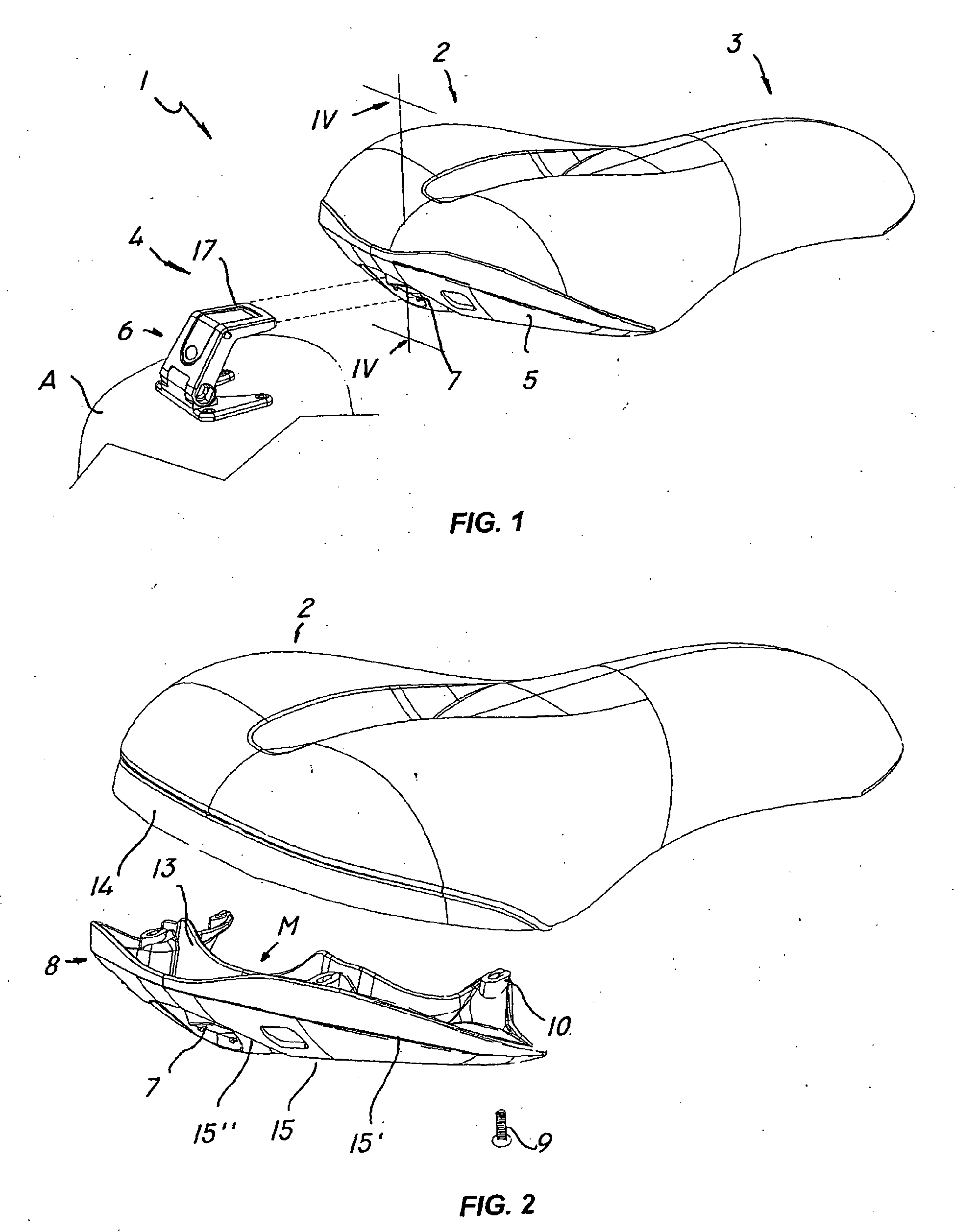
FIG. 1 is a perspective view of a saddle structure according to the invention;
FIG. 2 is a partly exploded view of a particular embodiment of the structure according
to the invention;
FIG. 3 is a perspective view of a detail of FIG. 2;
FIG. 4 is a sectional view of the structure of Fig. 1, as taken along a plane IV-IV.
Detailed description of a preferred embodiment
[0018] With reference to the above figures, the saddle structure of the invention, generally
designated by numeral 1, is of the type that can be classically anchored to a bicycle
frame, not depicted as being per se known.
[0019] The structure generally includes a widened rear portion 2, which is designed to receive
a seated user, and a tapered front portion 3, as shown in FIG. 1. Quick-connection
means are provided at the rear portion of the saddle 2 for connection of any accessory
indicated A, which may be a signal light, a reflector or a tool kit, as shown.
[0020] A peculiar feature of this invention is that, at the rear portion 2, the saddle has
an ergonomically shaped peripheral edge 5, which is at least partly beveled and rounded,
with no sharp edges, to define a comfortable and safe grip portion for a user to allow
lifting and handling of the bicycle. Furthermore, the quick-connection means, generally
designated by numeral 4, are located along the edge 5, to facilitate quick-connection/removal
of the accessory A to/from the saddle. An ergonomic and firm grasp is further ensured
by forming the edge 5 with an at least partially inwardly and downwardly inclination.
[0021] As shown in FIG. 1, the means 4 near the center portion M of the edge 5 include a
male member 6 connected to the accessory A and a female member 7 integral and monolithic
with the edge 5. It shall be understood that the members 6 and 7 may also be placed
on the edge 5 and the accessory A respectively, and the member on the edge 5 may also
be non monolithic therewith .
[0022] As particularly shown in FIG. 2, the edge 5 is defined by a profile 8 made of a rigid
or semi-rigid material, preferably but without limitation of the polymer type, to
be attached to the saddle by means of screws 9 to be received in special slots 10.
Otherwise, the edge 5 may be monolithic with the saddle, and the screw fastening means
9 may be replaced by or coupled to snap fitting means .
[0023] As is clearly shown in FIG. 3, the profile 8, which has a horseshoe shape, comprises
an internal connecting portion 11 and an external portion 12, the latter being designed
to contact the hand of a user.
[0024] Advantageously, the internal portion has a longitudinal recess 13 which is designed
to be coupled to a corresponding projection 14 at the rear portion 2 of the saddle.
On the other hand, the external portion 12 has rounded and/or tapered connecting edges
15, 15', 15" for preventing any accidental injury to a user.
[0025] The quick-connection means 4 may be formed as taught by the above mentioned international
patent application PCT/IB2005/000753.
[0026] In a preferred non-exclusive embodiment, the female member 7 is defined by a slot
in a recess 16 of the profile 8, whereas the male member 6 has an elongate extension
17 which is slideably engaged and snap fitted therein.
[0027] To assist the sliding motion of the extension 17 in the slot 7, the recess 16 has
suitably shaped guide surfaces 18, 18'.
[0028] As clearly shown in FIG. 4, to avoid any clearance between the elongate extension
17 of the male member 6 and the female member 7, the latter has detent means, generally
designated by numerals 19, 19', and preferably comprising a pair of specially shaped
receptacles 20, 20', to be engaged by a pair of corresponding guides 21, 21' on the
male member 6.
[0029] The above disclosure clearly shows that the structure of the invention fulfills the
intended objects and particularly the object of providing a saddle structure that
ensures a quick and firm connection/removal of the accessory to be carried to/from
the saddle, while allowing a comfortable and safe grasp of the saddle.
[0030] Thanks to the provision of the edge 5, which is shaped in such a manner as to define
a comfortable and safe grip portion for a user, and to the provision of the quick-connection
means 4 thereon, a multifunction saddle structure is obtained, allowing a comfortable
and pleasant use.
[0031] The structure of the invention is susceptible to a number of changes and variants,
within the inventive concept disclosed in the appended claims. All the details thereof
may be replaced by other technically equivalent parts, and the materials may vary
depending on different needs, without departure from the scope of the invention as
defined in the claims.
[0032] While the structure has been described with particular reference to the accompanying
figures, the numerals referred to in the disclosure and claims are only used for the
sake of a better intelligibility of the invention and shall not be intended to limit
the claimed scope in any manner.
1. A saddle structure with quick-connection means for attaching bicycle accessories,
comprising a saddle designed to be anchored to a bicycle frame, said saddle having
a tapered front portion (3) and a widened rear portion (2), an ergonomically shaped
peripheral edge (5) being provided in said widened rear portion (2), which edge (5)
is at least partly bevelled and rounded and has no sharp edges to define a comfortable
and safe grip portion (12) for a user, quick-connection means (4) being provided at
said rear portion (2), said quick-connection means (4) comprising only one of a male
(6) or a female member (7) designed to be coupled to the other of said male (6) or
female (7) member that is associated to one or more bicycle accessories (A), characterised in that said peripheral edge (5) is provided to said widened rear portion (2) under the saddle
and is at least partly inwardly and downwardly inclined, said quick-connection means
(4) being located below said grip portion (12) along said shaped edge (5) in order
not to interfere with the hand of the user when lifting and handling the bicycle.
2. Structure as claimed in claim 1, characterized in that said shaped edge (5) is integral and monolithic with said saddle.
3. Structure as claimed in claim 1, characterized in that said shaped edge (5) is defined by a profile (8) made of a rigid or semi-rigid material,
to be attached to the saddle by screw and/or snap fit means (9).
4. Structure as claimed in claim 3, characterized in that said profile (8) has an internal connecting portion (11) and an external grip portion
(12).
5. Structure as claimed in claim 4, characterized in that said connecting portion (11) has a longitudinal recess (13) which is designed to
be at least partly coupled to a corresponding projection (14) at said widened rear
portion (2).
6. Structure as claimed in claim 5, characterized in that said grip portion (12) has rounded and/or tapered connecting edges (15, 15', 15")
for preventing any accidental injury to a user.
7. Structure as claimed in claim 1, characterized in that said quick-connection means (4) are.located near the center portion (M) of said shaped
edge (5).
8. Structure as claimed in claim 1, characterized in that said one of said male member (6) and female member (7) is formed integrally and monolithically
with said shaped edge (5).
9. Structure as claimed in claim 1, characterized in that said female member (7) is formed integrally and monolithically with said shaped edge
(5).
10. Structure as claimed in claim 9, characterized in that said female member (7) comprises a slot in a recess (16) of said shaped edge (5).
11. Structure as claimed in claim 10, characterized in that said male member (6) has an elongate extension (17) which is slidingly engaged and
snap fitted in said slot (7).
12. Structure as claimed in claim 11, characterized in that said recess (16) has guide surfaces (18, 18') for assisting the sliding motion of
said elongate extension (17) in said slot (7).
13. Structure as claimed in claim 12, characterized in that said slot (7) has detent means (19, 19') for said male member (6).
14. Structure as claimed in claim 13, characterized in that said detent means (19, 19') comprise a pair of specially shaped receptacles (20,
20'), which are designed to be engaged by a pair of corresponding guides (21, 21')
on said male member (6).
1. Eine Sattelstruktur mit Schnellbefestigungsmitteln für den Anschluss von Fahrradzubehör,
einen für die Befestigung an einem Fahrradrahmen bestimmten Sattel umfassend, wobei
dieser Sattel einen länglichen vorderen Abschnitt (3) aufweist sowie einen breiteren
hinteren Abschnitt (2), einen ergonomisch geformten Außenrand (5), wobei dieser Rand
(5) in diesem hinteren, breiteren Abschnitt (2) wenigstens teilweise abgeschrägt und
abgerundet ist und keine scharfen Kanten aufweist, so dass ein Bereich (12) zum sicheren
und bequemen Greifen durch einen Benutzer gebildet wird, ein Schnellbefestigungsmittel
(4), wobei dieses Schnellbefestigungsmittel (4) in Entsprechung des hinteren Abschnitts
(2) lediglich ein männliches Element (6) oder ein weibliches Element (7) aufweist,
das geeignet ist, mit dem Gegenstück dieses männlichen (6) oder weiblichen Elements
(7) verbunden zu werden, welches einem oder mehreren Fahrradzubehörteilen (A) zugeordnet
ist, dadurch gekennzeichnet, dass der zum hinteren, breiteren Abschnitt (2) gehörige Außenrand (5) sich unter dem Sattel
befindet und wenigstens teilweise nach innen und nach unten geneigt ist, wobei das
Schnellbefestigungsmittel (4) unterhalb des Griffbereichs (12) an dem geformten Rand
(5) entlang positioniert ist, um die Hand des Benutzers nicht zu behindern, wenn Letzterer
das Fahrrad anhebt und bewegt.
2. Struktur gemäß Patentanspruch 1, dadurch gekennzeichnet, dass der geformte Rand (5) einen einheitlichen Körper mit dem Sattel bildet.
3. Struktur gemäß Patentanspruch 1, dadurch gekennzeichnet, dass der geformte Rand (5) durch ein Profil (8) aus starrem oder halbstarrem Material
besteht und mit Schrauben und/oder durch Einrasten (9) am Sattel befestigt wird.
4. Struktur gemäß Patentanspruch 3, dadurch gekennzeichnet, dass das Profil (8) einen internen Verbindungsabschnitt (11) und einen externen Griffabschnitt
(12) aufweist.
5. Struktur gemäß Patentanspruch 4, dadurch gekennzeichnet, dass der Verbindungsabschnitt (11) einen länglichen Hohlraum (13) aufweist, der dazu bestimmt
ist, wenigstens teilweise mit einer entsprechenden Auskragung (14) an dem hinteren,
breiteren Abschnitt (2) verbunden zu werden.
6. Struktur gemäß Patentanspruch 5, dadurch gekennzeichnet, dass der Griffabschnitt (12) abgerundete und/oder verlängerte Verbindungsränder (15, 15',
15") aufweist, um jegliche versehentliche Verletzung des Benutzers zu verhindern .
7. Struktur gemäß Patentanspruch 1, dadurch gekennzeichnet, dass die Schnellbefestigungsmittel (4) in der Nähe des mittleren Abschnitts (M) des geformten
Rands (5) positioniert sind.
8. Struktur gemäß Patentanspruch 1, dadurch gekennzeichnet, dass das männliche Element (6) und das weibliche Element (7) Bestandteile des geformten
Rands (5) sind und mit diesem ein einziges Teil bilden.
9. Struktur gemäß Patentanspruch 1, dadurch gekennzeichnet, dass das weibliche Element (7) Bestandteil des geformten Rands (5) ist und mit diesem
ein einziges Teil bildet.
10. Struktur gemäß Patentanspruch 9, dadurch gekennzeichnet, dass das weibliche Element (7) ein Langloch in einem Hohlraum des geformten Rands (5)
aufweist.
11. Struktur gemäß Patentanspruch 10, dadurch gekennzeichnet, dass das männliche Element (6) einen länglichen Ansatz (17) aufweist, der in das Langloch
(7) einrastet und in diesem gleitet.
12. Struktur gemäß Patentanspruch 11, dadurch gekennzeichnet, dass der Hohlraum (16) Gleitflächen (18, 18') für die Gleitbewegung des länglichen Ansatzes
(17) in dem Langloch (7) aufweist.
13. Struktur gemäß Patentanspruch 12, dadurch gekennzeichnet, dass das Langloch (7) Haltevorrichtungen (19, 19') für das männliche Element (6) aufweist.
14. Struktur gemäß Patentanspruch 13, dadurch gekennzeichnet, dass diese Haltevorrichtungen (19, 19') ein Paar besonders geformter Aufnahmen (20, 20')
umfassen, die dazu bestimmt sind, an einem entsprechenden Paar Führungen (21, 21')
an dem männlichen Element (6) fixiert zu werden.
1. Une structure de selle avec moyens d'attache rapide pour la fixation d'accessoires
de bicyclette, comprenant une selle destinée à être fixée à un cadre de bicyclette,
ladite selle présentant une portion antérieure allongée (3) et une portion postérieure
élargie (2), un bord (5) périphérique de forme ergonomique étant prévu sur ladite
portion postérieure élargie (2). Ce bord (5) est au moins partiellement émoussé et
arrondi et ne présente pas d'arêtes tranchantes de façon à définir une portion (12)
de prise sûre et pratique pour l'utilisateur, des moyens d'attache rapide (4) étant
prévus au niveau de ladite portion postérieure (2), lesdits moyens d'attache rapide
(4) comprenant seulement un entre un élément mâle (6) ou un élément femelle (7) destiné
à être couplé à l'autre dudit élément mâle (6) ou élément femelle (7) qui est associé
à un ou plusieurs accessoires de bicyclette (A), caractérisée en ce que ledit bord périphérique (5) équipe la portion postérieure élargie (2) sous la selle
et est au moins partiellement incliné vers l'intérieur et vers le bas, lesdits moyens
d'attache rapide (4) étant positionnés sous ladite portion de prise (12) le long dudit
bord profilé (5), de sorte qu'ils n'interfèrent pas avec la main de l'utilisateur
lorsque celui-ci soulève et manoeuvre la bicyclette.
2. Structure selon la revendication 1, caractérisée en ce que ledit bord profilé (5) est intégral et fait corps avec ladite selle.
3. Structure selon la revendication 1, caractérisée en ce que ledit bord profilé (5) est défini par un profil (8) en matériau rigide ou semi-rigide,
à fixer à la selle par des moyens à vis et/ou à enclenchement (9).
4. Structure selon la revendication 3, caractérisée en ce que ledit profil (8) présente une portion de jonction interne (11) et une portion de
prise externe (12).
5. Structure selon la revendication 4, caractérisée en ce que ladite portion de jonction (11) présente une cavité longitudinale (13) qui est destinée
à être au moins partiellement couplée à une saillie (14) correspondante au niveau
de ladite portion postérieure élargie (2).
6. Structure selon la revendication 5, caractérisée en ce que ladite portion de prise (12) présente des bords de jonction arrondis et/ou allongés
(15, 15', 15") pour empêcher toute lésion accidentelle de l'utilisateur.
7. Structure selon la revendication 1, caractérisée en ce que lesdits moyens d'attache rapide (4) sont positionnés à proximité de la portion centrale
(M) dudit bord profilé (5).
8. Structure selon la revendication 1, caractérisée en ce que ledit un entre ledit élément mâle (6) et élément femelle (7) est intégralement formé
et fait corps avec ledit bord profilé (5).
9. Structure selon la revendication 1, caractérisée en ce que ledit élément femelle (7) est intégralement formé et fait corps avec ledit bord profilé
(5).
10. Structure selon la revendication 9, caractérisée en ce que ledit élément femelle (7) comprend une fente dans une cavité (16) dudit bord profilé
(5).
11. Structure selon la revendication 10, caractérisée en ce que ledit élément mâle (6) présente un appendice allongé (17) qui est engagé par glissement
et inséré par enclenchement dans ladite fente (7).
12. Structure selon la revendication 11, caractérisée en ce que ladite cavité (16) présente des surfaces de guidage (18, 18') pour accompagner le
mouvement de glissement dudit appendice allongé (17) dans ladite fente (7).
13. Structure selon la revendication 12, caractérisée en ce que ladite fente (7) présente des moyens d'arrêt (19, 19') pour ledit élément mâle (6).
14. Structure selon la revendication 13, caractérisée en ce que lesdits moyens d'arrêt (19, 19') comprennent une paire de logements (20, 20') de
forme spéciale qui sont destinés à être engagés par une paire de guides correspondants
(21, 21') sur ledit élément mâle (6).

REFERENCES CITED IN THE DESCRIPTION
This list of references cited by the applicant is for the reader's convenience only.
It does not form part of the European patent document. Even though great care has
been taken in compiling the references, errors or omissions cannot be excluded and
the EPO disclaims all liability in this regard.
Patent documents cited in the description