| (19) |
 |
|
(11) |
EP 1 810 946 B1 |
| (12) |
EUROPEAN PATENT SPECIFICATION |
| (45) |
Mention of the grant of the patent: |
|
19.08.2009 Bulletin 2009/34 |
| (22) |
Date of filing: 11.01.2007 |
|
| (51) |
International Patent Classification (IPC):
|
|
| (54) |
Bottle filling valve to be used in aseptic industrial bottling systems for juices,
beverages and in general for so-called still beverages
Flaschenfüllventil zur Verwendung in aseptischen industriellen Abfüllsystemen für
Säfte, Getränke und allgemein für sogenannte stille Getränke
Soupape de remplissage de bouteilles à utiliser dans des systèmes aseptiques d'embouteillage
industriel pour jus, boissons et en général pour les boissons dites plates
|
| (84) |
Designated Contracting States: |
|
AT BE BG CH CY CZ DE DK EE ES FI FR GB GR HU IE IS IT LI LT LU LV MC NL PL PT RO SE
SI SK TR |
| (30) |
Priority: |
18.01.2006 IT PD20060015
|
| (43) |
Date of publication of application: |
|
25.07.2007 Bulletin 2007/30 |
| (73) |
Proprietor: ACQUA MINERALE SAN BENEDETTO S.p.A. |
|
I-30037 Scorze' (Prov. of Venezia) (IT) |
|
| (72) |
Inventor: |
|
- Zoppas, Enrico
31015 Conegliano Veneto (TV) (IT)
|
| (74) |
Representative: Modiano, Micaela Nadia et al |
|
Dr. Modiano & Associati SpA
Via Meravigli 16
20123 Milano
20123 Milano (IT) |
| (56) |
References cited: :
EP-A1- 0 906 889
DE-B- 1 221 571
FR-A1- 2 842 799
US-A- 4 269 236
|
DE-A1- 3 325 338
FR-A1- 2 322 092
FR-A3- 2 721 305
|
|
| |
|
|
|
|
| |
|
| Note: Within nine months from the publication of the mention of the grant of the European
patent, any person may give notice to the European Patent Office of opposition to
the European patent
granted. Notice of opposition shall be filed in a written reasoned statement. It shall
not be deemed to
have been filed until the opposition fee has been paid. (Art. 99(1) European Patent
Convention).
|
[0001] The present invention relates to a bottle filling valve to be used in aseptic industrial
bottling systems for juices, beverages, and in general for so-called still beverages.
[0002] As is known, bottling systems for beverages intended for mass consumption must perform
bottling at extremely variable rates and must have a high productivity (typically
expressed as filled bottles per hour) in order to be able to achieve the necessary
economies of scale.
[0003] These systems are further required to have a certain production flexibility in order
to be able to bottle beverages having different flavors and bottle bottles having
different volumes.
[0004] Moreover, the particular and delicate environment in which bottling is performed,
which must be substantially aseptic in order to avoid the proliferation of germs and
bacteria inside the bottles once they have been bottled, forces bottling systems to
perform frequent sterilizing and sanitizing cycles.
[0005] The bottle filling step is performed by means of a certain number of filling valves;
these valves are generally the parts of the system that have a decisive role in the
filling rate.
[0006] In filling valves, it is important that germs and bacteria cannot enter the filling
duct, which generally ends with a sleeve which is inserted in the bottle.
[0007] In known valves, in particular in the case of valves of the mechanical type, this
often does not occur, since coaxial parts which compose the filling duct can move
with respect to each other in order to allow the opening of a flow control element
which closes said duct.
[0008] The interface between such mutually moving parts is a preferential path for the entry
of germs into the duct, in particular because the interface has a portion which is
exposed to the outside environment; during the relative movement of the parts, said
portion is carried inside the structure of the valve, facilitating the advancement
of the germs toward the duct.
[0009] Further, the structures of known valves are complicated and therefore have substantial
costs for their production and maintenance difficulties, and this is particularly
critical in view of the continuous bottling cycles.
[0010] DE 33 25 338 A1 discloses a bottle filling valve in accordance with the precharacterising portion
of the appended claim 1.
[0011] The aim of the present invention is to solve the problems noted in known types of
bottle filling valve.
[0012] Within this aim, an object of the present invention is to provide a bottle filling
valve to be used in aseptic industrial bottling systems for juices, beverages and
in general for so-called still beverages, which allows to maintain a high level of
asepsis during operation.
[0013] Another object of the present invention is to provide a bottle filling valve to be
used in aseptic industrial bottling systems for juices, beverages and in general for
so-called still beverages which allows a high filling rate.
[0014] Another object of the present invention is to provide a bottle filling valve to be
used in aseptic industrial bottling systems for juices, beverages and in general for
so-called still beverages which is structurally simple.
[0015] In accordance with the invention, there is provided a bottle filling valve as defined
in the appended claims.
[0016] Further characteristics and advantages of the invention will become better apparent
from the following detailed description of a preferred but not exclusive embodiment
thereof, illustrated by way of non-limiting example in the accompanying drawings,
therein:
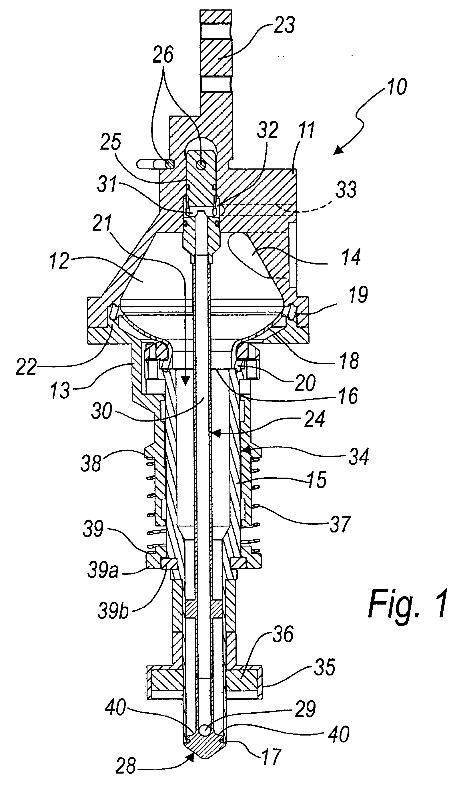
Figure 1 is a sectional view, taken along its main axis, of a bottle filling valve
according to the invention during closure;
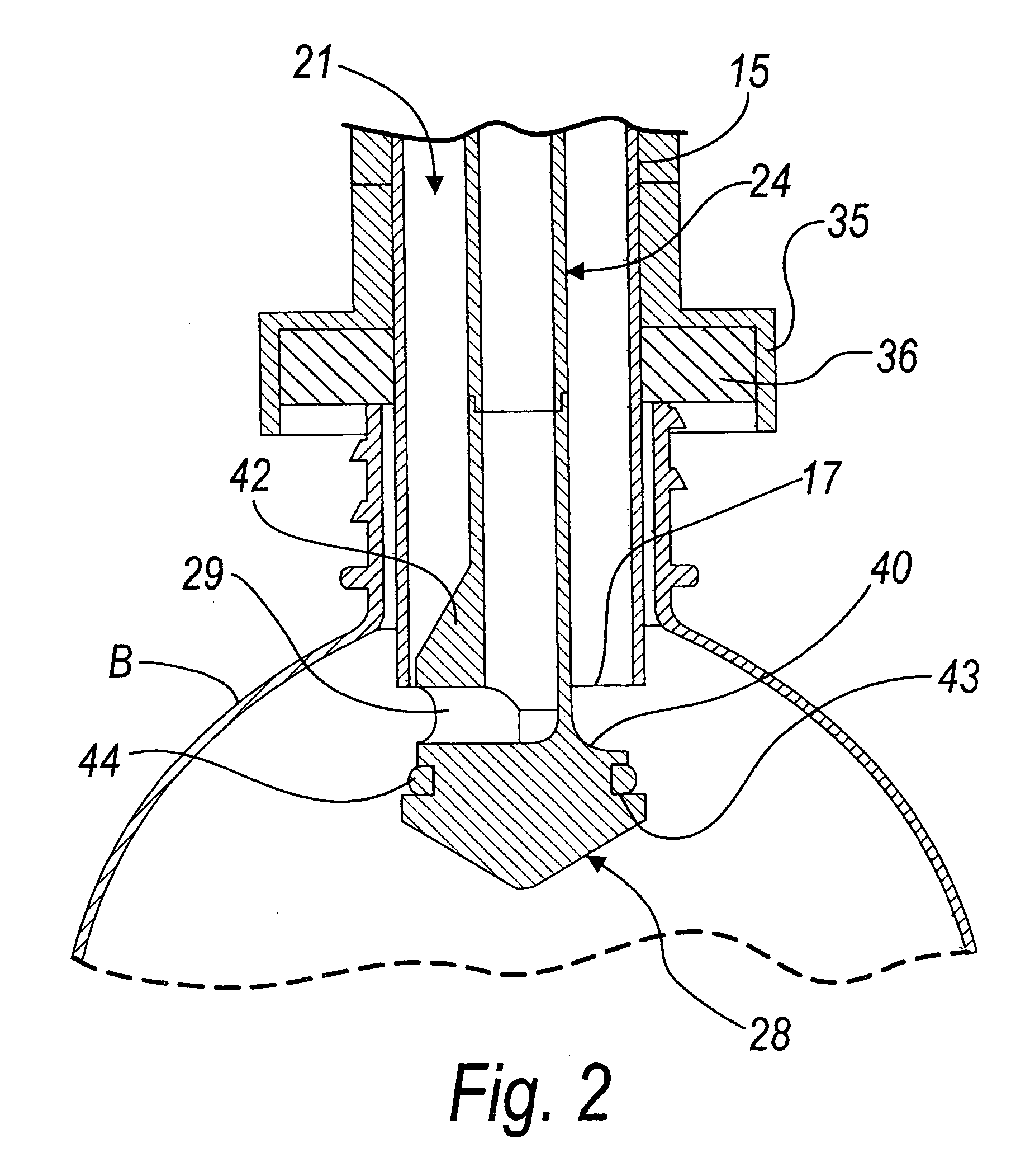
Figure 2 is a sectional view, taken along a plane which is perpendicular to the plane
of Figure 1, of a detail of the filling valve during opening-discharge.
[0017] It is noted that anything found to be already known during the patenting process
is understood not to be claimed and to be the subject of a disclaimer.
[0018] With reference to the figures, a bottle filling valve according to the invention
is generally designated by the reference numeral 10.
[0019] The valve 10 comprises an upper body 11, in which there is a chamber 12 which is
open downward, and a lower tubular body 13, which is fixed to the upper body 11 at
the lower rim of the chamber 12.
[0020] The chamber 12 is connected to a liquid supply system (not shown in the figures)
by means of an access hole 14.
[0021] Below the chamber 12, in a position which is partially internal and coaxial with
respect to the lower body 13, there is a sleeve 15 to be inserted in the bottle to
be filled (which is shown schematically and partially in Figure 2 and designated by
the reference letter B).
[0022] The sleeve 15 has, at its upper and lower ends, respectively an opening 16 for connection
to the chamber 12 and a port 17 for discharge into the bottle.
[0023] The chamber 12 and the sleeve 15 are mutually connected by means of a connecting
member which is formed by an annular membrane 18 made of plastic material, which is
elastic and impermeable and is fixed by its outer perimetric portion 19 to the lower
rim of the chamber 12 and by its inner perimetric portion 20 to the upper rim of the
sleeve 15.
[0024] The chamber 12, the wall of the annular membrane 18 and the sleeve 15 form the bottle
filling duct 21.
[0025] In particular, the outer perimetric portion 19 of the annular membrane 18 is locked
in a sandwich-like fashion between the lower rim of the chamber 12 and an annular
ridge 22 which is formed on the upper part of the lower body 13.
[0026] The upper body 11 has a part 23 for fixing to the structure for supporting and moving
the valve 10, which is not shown in the figures.
[0027] A tubular stem 24 is provided inside the filling duct 21, is fixed in an upper region
on the top of the chamber 12, and is coaxial to the sleeve 15.
[0028] The tubular stem 24 is locked by inserting the head 24a of the stem 24 in a seat
25 which is formed in the upper body 11 and the corresponding reversible locking in
the seat of the head 24a for its coupling with a fork-like pin 26, which is removable
and can be arranged outside the upper body 11.
[0029] The tubular stem 24 has, at its lower end, a flow control body 28 for the discharge
port 17 of the sleeve 15.
[0030] A vent hole 29 leads out laterally on the flow control body 28 and is connected to
the inside 30 of the tubular stem 24, which in turn is connected to an external system
for venting and/or recovering liquid, not shown in the figures.
[0031] In particular, the interior 30 of the tubular stem 24 ends on a transverse hole 31
formed in the head 24a of said stem, which in turn is open onto an annular slot 32
which is formed in the seat 25 and is isolated upward and downward by gaskets.
[0032] A connecting duct 33 is open on the annular slot 32 and connects it to said external
system for venting and/or recovering liquid.
[0033] The sleeve 15 comprises means 34 which are suitable to allow it to perform a relative
translational motion with respect to the tubular stem 24 from a position in which
the discharge port 17 is closed onto the flow control body 28 (Figure 1) to a position
in which the port 17 is raised from the flow control body 28 (Figure 2) when the sleeve
is inserted into the bottle to be filled.
[0034] The means 34, termed hereinafter "translational means 34", consist of the cylindrical
guide constituted by the internal surface of the lower body 13, which is substantially
tubular, and of an abutment ring 35, which is fixed coaxially to the portion of the
sleeve 15 that protrudes from the lower body 13 (the operation of which will be explained
hereinafter).
[0035] The abutment ring 35 is provided internally with an annular gasket 36 against which
the rim of the mouth of the bottle abuts.
[0036] Means for returning the discharge port 17 to the closure position on the flow control
body 28 are associated with the translational means 34 and are constituted by a spring
37, which is arranged coaxially to the lower body 13 and to the sleeve 15 between
a first annular abutment 38, formed on the lower body 13, and a second annular abutment
39, associated with the sleeve 15.
[0037] In particular, the second annular abutment 39 is constituted by an annular body 39a,
which is arranged in abutment against two half-rings 39b which are inserted in corresponding
annular slots formed on the outer surface of the sleeve 15.
[0038] The maximum relative translational motion between the sleeve 15 and the tubular stem
14 is equal to the distance between the lower body 13 and the annular abutment 39.
[0039] The flow control body 28 has, for a portion of its rotation about the axis of the
tubular stem 24, a portion 40 for blending with said tubular stem which tapers upward
so as to form a chute for conveyance toward the wall of the bottle for the liquid
that exits from the filling duct 21.
[0040] A rib 42 is provided on the angular blending portion between the flow control body
28 and the tubular stem 24 which is not tapered and has a radial extension equal to
the distance between the lateral surface of the tubular stem 24 and the internal surface
of the sleeve 15 (as clearly shown in Figure 2, in which the flow control body is
shown in cross-section with respect to a plane which is perpendicular to the sectional
plane of Figure 1).
[0041] The vent hole 29 is provided on the face of the rib 42 which is directed toward the
sleeve 15.
[0042] The rib 42, conveniently blended with the tubular stem 24, prevents the liquid being
discharged from blocking the vent hole 29.
[0043] The flow control body 28 has an annular shoulder 43, which is formed below the blending
portion 40 and against which the discharge port 17 of the sleeve 15 abuts for closure;
a gasket 44, for example of the O-Ring type, is provided at the annular shoulder 43.
[0044] Advantageously, guiding wings 45 protrude from mutually opposite portions of the
outer lateral surface of the tubular stem 24 and have a radial dimension which is
substantially equal to the distance between said outer lateral surface of the tubular
stem 24 and the inner surface of the sleeve 15.
[0045] The operation of the valve is as follows.
[0046] The upper body 11 is fixed to a supporting and movement structure, while the sleeve
15 abuts against the discharge port 17 on the flow control body 28 (which is rigidly
coupled to the upper body 11) by way of the thrust of the spring 37; the sleeve 15
is connected to the upper body 11 by the annular membrane 18.
[0047] A bottle B is moved below the valve 10; said valve is lowered, moving the sleeve
15 into the mouth of the bottle and arranging the abutment ring 35 on the rim of said
mouth of the bottle.
[0048] The descent of the valve continues for a certain extent, so that the rim of the mouth
of a bottle pushes against the abutment ring 35 by way of the contact with the gasket
36, with the consequence of producing the upward translational motion of the sleeve
15 with respect to the lower body 13 and therefore with respect to the upper body
11 with the tubular stem 24; accordingly, said sleeve rises from the flow control
body 28, thus opening the discharge port, with the consequent descent of liquid.
[0049] Opening occurs by virtue of the very weight of the valve 11 which, being supported
by the bottle B, overcomes the force of the spring 37.
[0050] The descent of the liquid continues until it reaches the vent hole 29.
[0051] At this point, dispensing is interrupted and the excess product flows out, through
the vent hole 29, from the liquid venting and/or recovery system, thus determining
the level inside the bottle.
[0052] Once filling has ended, the valve 10 is raised and the sleeve 15, by virtue of its
own weight and of the return spring, returns to the closure condition on the flow
control body.
[0053] In practice it has been found that the invention thus described solves the problems
noted in known types of filling valve; in particular, the present invention provides
a bottle filling valve to be used in aseptic industrial bottling systems for juices,
beverages and in general for so-called still beverages which allows to avoid entraining
gems and bacteria into the filling duct.
[0054] By way of the annular membrane which connects the chamber to the sleeve, a relative
movement of the two parts of the duct is obtained without however forming any interface
which might constitute a preferential path for the penetration of germs into the duct.
[0055] The structure of the valve is further extremely simple, facilitating its production
and maintenance.
[0056] The shape of the flow control body and the size of the interior 30 of the tubular
stem 24 further allow to optimize the flow of liquid that enters the bottle, with
a considerable increase in the filling rate with respect to known valves.
[0057] The invention thus conceived is susceptible of numerous modifications and variations,
all of which are within the scope of the appended claims; all the details may further
be replaced with other technically equivalent elements.
[0058] In practice, the materials employed, so long as they are compatible with the specific
use, as well as the dimensions, may be any according to requirements and to the state
of the art.
[0059] Where technical features mentioned in any claim are followed by reference signs,
those reference signs have been included for the sole purpose of increasing the intelligibility
of the claims and accordingly such reference signs do not have any limiting effect
on the interpretation of each element identified by way of example by such reference
signs.
1. A bottle filling valve to be used in aseptic industrial bottling systems for juices,
beverages and in general for so-called still beverages, comprising a filling duct
(21), which is substantially straight and is constituted, from the top downward, by
an upper body (11), in which there is a chamber (12) which is open downward and is
connected to a liquid supply system, and by a sleeve (15) to be inserted in a bottle
(B) to be filled, said sleeve (15) being in a position which is partially internal
and coaxial to a lower tubular body (13) fixed to said upper body (11), said sleeve
(15) having, at its upper and lower ends, respectively an opening (16) for connection
to said chamber (12) and a port (17) for discharge into the bottle, said chamber (12)
and said sleeve (15) being mutually connected by means of a connecting member formed
by an annular elastic and impermeable membrane (18), which is fixed by means of its
outer perimetric portion (19) to the lower rim of said chamber (12) and by means of
its inner perimetric portion (20) to the upper rim of said sleeve (15), a tubular
stem (24) being provided inside said filling duct (21) and being fixed in an upper
region on the top of said chamber (12) and having, at its lower end, a flow control
body (28) for said discharge port (17) of said sleeve (15), a vent hole (29) being
provided in said flow control body (28) and being connected to the inside of said
tubular stem (24), which in turn is connected to an external system for venting and/or
recovering liquid, said sleeve (15) comprising means (34) suitable to allow it to
perform a relative translational motion with respect to said tubular stem (24) from
a position in which the discharge port (17) is closed onto said flow control body
(28) to a position in which said discharge port (17) is raised from said flow control
body (28) when said sleeve (15) is inserted in the bottle to be filled, means for
the return to the closure position of said discharge port (17) on said flow control
body (28) being associated with said means for translational motion (34), the bottle
filling valve being characterized in that said lower tubular body (13) is fixed to said upper body (11) at the lower rim of
said chamber (12), below said chamber (12), said outer perimetric portion (19) of
said annular membrane (18) being locked in a sandwich-like fashion between the lower
rim of said chamber (12) and an annular ridge (22) which is provided on the upper
part of said lower body (13).
2. The bottle filling valve according to claim 1, characterized in that said tubular stem (24) is coaxial to said sleeve (15) and in that said flow control body (28) has, for a portion of its rotation about the axis of
said tubular stem (24), a portion (40) for blending with said tubular stem (24) which
tapers upward so as to form a chute for conveyance toward the wall of the bottle (B)
for the liquid that exits from said sleeve (15), a rib (42) being provided on the
angular blending portion between said flow control body (28) and said tubular stem
(24) which is not tapered, said rib having a radial extension whose dimensions are
equal to the distance between the lateral surface of said tubular stem (24) and the
internal surface of said sleeve (15), said vent hole (29) being provided on the face
of said rib (42) which is directed toward said sleeve (15).
3. The bottle filling valve according to one of the preceding claims, characterized in that said tubular stem (24) is locked by inserting the head (24a) of said tubular stem
(24) in a seat (25) provided in said upper body (11) and by reversible locking in
said seat by coupling to a fork-like pin (26) which can be extracted and can be arranged
outside said upper body (11).
4. The bottle filling valve according to one of the preceding claims, characterized in that the interior (30) of said tubular stem (24) ends on a transverse hole (31) provided
in said head (24a) of said tubular stem (24), which in turn is open onto an annular
slot (32) which is formed in said seat (25) and is insulated upward and downward by
gaskets, a connecting duct (33) being open on said annular slot (32) for connection
to said external system for venting and/or recovering liquid.
5. The bottle filling valve according to one of the preceding claims, characterized in that said means (34) suitable to allow it to perform a relative translational motion with
respect to said tubular stem (24) consist of the cylindrical guide formed by the internal
surface of said lower body (13) and of an abutment ring (35) which is flexed coaxially
to the portion of said sleeve (15) which protrudes from said lower body (13), said
abutment ring (35) being provided internally with an annular gasket (36) against which
the rim of the mouth of the bottle abuts.
6. The bottle filling valve according to one of the preceding claims, characterized in that said means for returning to the closure position said discharge port (17) on the
flow control body (28) are constituted by a spring (37), which is arranged coaxially
to said lower body (13) and to said sleeve (15) between a first annular abutment (38),
provided on said lower body (13) and a second annular abutment (39), which is associated
with said sleeve (15).
7. The bottle filling valve according to claim 6, characterized in that said second annular abutment (39) is constituted by an annular body (39a) which is
arranged in abutment on two half-rings (39b), which are inserted in corresponding
annular slots provided on the outer surface of said sleeve (15).
8. The bottle filling valve according to claim 2, characterized in that said rib (42) is blended with said tubular stem (24).
9. The bottle filling valve according to one of the preceding claims, characterized in that guiding wings (45) protrude from mutually opposite portions of the outer lateral
surface of said tubular stem (24) and have, in a radial direction, dimensions which
are substantially equal to the distance between said outer lateral surface of said
tubular stem (24) and the internal surface of said sleeve (15).
10. The bottle filling valve according to claim 2, characterized in that said flow control body (28) has an annular shoulder (43), which is formed below said
blending portion (40), against which said discharge port (17) of the sleeve (15) abuts
for closure, a gasket (44) being provided at said annular shoulder (43).
1. Flaschenfüllventil zur Verwendung in aseptischen industriellen Flaschenfüllsystemen
für Säfte, Getränke und allgemein für sogenannte stille Getränke, mit einem Füllkanal
(21), der im Wesentlichen gerade und, von oben nach unten, aus einem oberen Gehäuse
(11), in dem eine Kammer (12) ist, die nach unten offen und mit einem Flüssigkeitszufuhrsystem
verbunden ist, und aus einer Hülse (15), die in eine zu befüllende Flasche (B) einzuführen
ist, gebildet ist, wobei die Hülse (15) in einer Lage ist, die teilweise innerhalb
und koaxial zu einem unteren rohrförmigen Gehäuse (13) ist, das an dem oberen Gehäuse
(11) befestigt ist, wobei die Hülse (15) eine Öffnung (16) zum Anschluss an die Kammer
(12) und eine Öffnung (17) für den Ausstoß in die Flasche an ihrem oberen bzw. unteren
Ende hat, wobei die Kammer (12) und die Hülse (15) mittels eines Verbindungsteiles
miteinander verbunden sind, das aus einer ringförmigen elastischen und undurchlässigen
Membran (18) besteht, die mittels ihres äußeren Umfangsteiles (19) an dem unteren
Rand der Kammer (12) und mittels ihres inneren Umfangsteiles (20) an dem oberen Rand
der Hülse (15) befestigt ist, wobei ein rohrförmiger Stab (24) in dem Kanal (21) vorgesehen
und in einem oberen Bereich an dem oberen Ende der Kammer (12) befestigt ist und an
seinem unteren Ende einen Strömungssteuerungskörper (28) für die Ausstoßöffnung (17)
der Hülse (15) hat, wobei ein Entlüftungsloch (29) in dem Strömungssteuerungskörper
(28) vorgesehen und mit der Innenseite des rohrförmigen Stabes (24) verbunden ist,
der wiederum mit einem externen System zum Entlüften und/oder Wiedergewinnen von Flüssigkeit
verbunden ist, wobei die Hülse (15) Mittel (34) aufweist, die geeignet sind, um ihr
zu gestatten, eine relative Translationsbewegung bezüglich des rohrförmigen Stabes
(24) aus einer Stellung, in der die Ausstoßöffnung (17) durch den Strömungssteuerungskörper
(28) geschlossen ist, in eine Stellung, in der die Ausstoßöffnung - (17) von dem Strömungssteuerungskörper
(28) abgehoben ist, wenn die Hülse (15) in eine zu befüllende Flasche eingeführt ist,
durchzuführen, wobei Mittel für die Rückkehr in die Schließstellung der Ausstoßöffnung
(17) an dem Strömungssteuerungskörper (28) mit den Mitteln für eine Translationsbewegung
(34) verbunden sind, wobei das Flaschenfüllventil dadurch gekennzeichnet ist, dass das untere rohrförmige Gehäuse (13) an dem oberen Gehäuse (11) an dem unteren Rand
der Kammer (12) unter der Kammer (12) befestigt ist, wobei der äußere Umfangsteil
(19) der ringförmigen Membran (18) sandwichartig zwischen dem unteren Rand der Kammer
(12) und einem ringförmigen Wulst (22), der an dem oberen Teil des unteren Gehäuses
(13) vorgesehen ist, festgehalten ist.
2. Flaschenfüllventil nach Anspruch 1, dadurch gekennzeichnet, dass der rohrförmige Stab (24) koaxial zu der Hülse (15) ist, und dass der Strömungssteuerungskörper
(28) über einen Teil seiner Drehung um die Achse des rohrförmigen Stabes (24) einen
Teil (40) zum Ineinandergehen mit dem rohrförmigen Stab (24) hat, der sich nach oben
verjüngt, um eine Rutsche zum Fördern der aus der Hülse (15) austretenden Flüssigkeit
in Richtung auf die Wand der Flasche (B) zu bilden, wobei eine Rippe (42) an dem winkelförmigen
Übergangsteil zwischen dem Strömungssteuerungskörper (28) und dem rohrförmigen Stab
(24), der nicht verjüngt ist, vorgesehen ist, wobei die Rippe eine radiale Ausdehnung
hat, deren Abmessungen gleich dem Abstand zwischen der seitlichen Fläche des rohrförmigen
Stabes (24) und der inneren Fläche der Hülse (15) ist, wobei das Entlüftungsloch (29)
auf der Außenseite der Rippe (42) vorgesehen ist, die auf die Hülse (15) gerichtet
ist.
3. Flaschenfüllventil nach einem der vorhergehenden Ansprüche, dadurch gekennzeichnet, dass der rohrförmige Stab (24) durch Einführen des Kopfes (24a) des rohrförmigen Stabes
(24) in einen in dem oberen Gehäuse (11) vorgesehenen Sitz (25) und durch umkehrbares
Festhalten in dem Sitz durch Verbinden mit einem gabelähnlichen Stift (26), der herausgezogen
und außerhalb des oberen Gehäuses (11) angeordnet werden kann, festgehalten wird.
4. Flaschenfüllventil nach einem der vorhergehenden Ansprüche, dass die Innenseite (30)
des rohrförmigen Stabes (24) an einem in dem Kopf (24a) des rohrförmigen Stabes (24)
vorgesehenen querverlaufenden Loch (31) endet, das wiederum zu einem ringförmigen
Schlitz (32) hin offen ist, der in dem Sitz (25) gebildet und nach oben und nach unten
durch Dichtungen isoliert ist, wobei ein Verbindungskanal (33) zu dem ringförmigen
Schlitz (32) zum Anschluss an das externe System zum Entlüften und/oder Wiedergewinnen
von Flüssigkeit offen ist.
5. Flaschenfüllventil nach einem der vorhergehenden Ansprüche, dadurch gekennzeichnet, dass die Mittel (34), die geeignet sind, um ihr zu gestatten, eine relative Translationsbewegung
bezüglich des rohrförmigen Stabes (24) durchzuführen, aus der zylindrischen Führung,
die von der inneren Oberfläche des unteren Gehäuses (13) gebildet wird und aus einem
Widerlagerring (35) bestehen, der koaxial zu dem Abschnitt der Hülse (15) befestigt
ist, der von dem unteren Gehäuse (13) vorsteht, wobei der Widerlagerring (35) innen
mit einer ringförmigen Dichtung (36) versehen ist, an die der Rand der Öffnung der
Flasche anstößt.
6. Flaschenfüllventil nach einem der vorhergehenden Ansprüche, dadurch gekennzeichnet, dass die Mittel zum Zurückführen der Ausstoßöffnung (17) in die Schließstellung an dem
Strömungssteuerkörper (28) aus einer Feder (37) bestehen, die koaxial zu dem unteren
Gehäuse (13) und der Hülse (15) zwischen einem ersten ringförmigen Widerlager (38),
das an dem unteren Gehäuse (13) vorgesehen ist, und einem zweiten ringförmigen Widerlager
(39), das mit der Hülse (15) verbunden ist, angeordnet ist.
7. Flaschenfüllventil nach Anspruch 6, dadurch gekennzeichnet, dass das zweite ringförmige Widerlager (39) von einem ringförmigen Körper (39a) gebildet
wird, der in Anlage an zwei Halbringen (39b) angeordnet ist, die in entsprechende
ringförmige Schlitze eingesetzt sind, die an der äußeren Oberfläche der Hülse (15)
vorgesehen sind.
8. Flaschenfüllventil nach Anspruch 2, dadurch gekennzeichnet, dass die Rippe (42) in den rohrförmigen Stab (24) übergeht.
9. Flaschenfüllventil nach einem der vorhergehenden Ansprüche, dadurch gekennzeichnet, dass Führungsflügel (45) von einander entgegengesetzten Abschnitten der äußeren seitlichen
Fläche des rohrförmigen Stabes (24) abstehen und in einer Radialrichtung Abmessungen
haben, die im Wesentlichen gleich dem Abstand zwischen der äußeren seitlichen Oberfläche
des rohrförmigen Stabes (24) und der inneren Oberfläche der Hülse (15) sind.
10. Flaschenfüllventil nach Anspruch 2, dadurch gekennzeichnet, dass der Strömungssteuerungskörper (28) einen ringförmigen Absatz (43) hat, der unter
dem Übergangsteil (40) gebildet ist, an dem die Ausstoßöffnung (17) der Hülse (15)
zum Schließen anstößt, wobei eine Dichtung (44) an dem ringförmigen Absatz (43) vorgesehen
ist.
1. Valve de remplissage de bouteille destinée à être utilisée dans des systèmes de mise
en bouteille industrielle pour des jus, boissons et en général boissons non gazeuses,
comportant un conduit (21) de remplissage, qui est sensiblement droit et est constitué,
à partir de l'extrémité inférieure, par un corps supérieur (11), dans lequel est prévue
une chambre (12) ouverte vers le bas et est reliée à un système d'alimentation de
liquide, et par un manchon (15) destiné à être inséré dans une bouteille (B) destinée
à être remplie, ledit manchon (15) étant dans une position qui est partiellement interne
et coaxiale à un corps tubulaire inférieur (13) fixé audit corps (11) supérieur, ledit
manchon (15) ayant, à ses extrémités supérieure et inférieure, respectivement une
ouverture (16) pour liaison à ladite chambre (12) et un port (17) pour décharge dans
la bouteille, ladite chambre (12) et ledit manchon étant mutuellement liés au moyen
d'un élément de connexion formé par une membrane (18) imperméable, élastique et annulaire,
qui est fixée au moyen de sa partie de périmètre extérieur (19), à la périphérie inférieure
de ladite chambre (12), et au moyen de sa partie de périmètre (20) intérieure au périmètre
extérieur dudit manchon (15), une tige tubulaire (24) étant prévue à l'intérieur dudit
conduit de remplissage (21) et étant fixée dans une partie supérieure du sommet de
ladite chambre (12) et ayant à son extrémité inférieure un corps (28) de commande
d'écoulement pour ledit port d'évacuation (17) dudit manchon (15), un trou d'évacuation
(29) étant prévu dans ledit corps (28) de commande d'écoulement et étant relié à l'intérieur
de ladite tige (24) tubulaire, qui à son tour est reliée à un système externe pour
évacuer et/ou récupérer du liquide, ledit manchon (15) comprenant des moyens (34)
aptes à permettre à ce dernier de réaliser un mouvement relatif de translation par
rapport à ladite tige tubulaire (24), à partir d'une position dans laquelle le port
(17) d'évacuation est fermé sur ledit corps (28) de commande d'écoulement en une position
dans laquelle ledit port (17) d'évacuation est relevé par rapport audit corps (28)
de commande d'écoulement lorsque ledit manchon (15) est inséré dans la bouteille destinée
à être remplie, des moyens pour le retour en position fermée dudit port d'évacuation
(17) sur ledit corps de commande d'évacuation (28), étant associés auxdits moyens
pour ledit mouvement de translation (34), la valve étant caractérisée en ce que ledit cops (13) tubulaire inférieur est fixé audit corps supérieur (11) en la périphérie
inférieure de ladite chambre (12), sous ladite chambre (12), ladite partie (19) de
périmètre extérieure de ladite membrane (18) annulaire étant bloquée en sandwich entre
la périphérie inférieure de ladite chambre (12) et une arête (22) annulaire qui est
prévue sur la partie supérieure dudit corps inférieur (13).
2. Valve de remplissage de bouteille selon la revendication 1, caractérisée en ce que ladite tige tubulaire (24) et coaxiale audit manchon (15) et en ce que ledit corps (28) de commande d'écoulement présente, pour une partie de sa rotation
autour de l'axe de ladite tige (24) tubulaire, une partie (40) confondue avec ladite
tige (24) tubulaire qui s'amincit vers le haut afin de former une chute pour évacuation
vers la paroi de la bouteille (B) pour le liquide qui sort dudit manchon (15), une
nervure (42) étant prévue sur la partie confondue angulaire entre ledit corps de commande
d'écoulement (28) et ladite tige tubulaire (24) qui n'est pas amincie, ladite nervure
ayant une extension radiale dont les dimensions sont égales à la distance entre la
surface latérale de ladite tige tubulaire (24) et la surface interne dudit manchon
(15), ledit trou d'évacuation (29) étant prévu sur la face de ladite nervure (42)
qui est dirigée vers ledit manchon (15).
3. Valve selon l'une des revendications précédentes, caractérisée en ce que ladite tige (24) tubulaire est bloquée par l'insertion de la tête (24a) de ladite
tige (24) tubulaire dans un siège (25) prévu sur ledit corps supérieur (11) par un
mécanisme de blocage réversible dans ledit siège par couplage à une aiguille (26)
en fourche qui peut être extraite et peut être disposée à l'extérieur dudit corps
(11) supérieur.
4. Valve selon l'une des revendications précédentes, caractérisée en ce que l'intérieur (30) de ladite tige (24) tubulaire se termine sur un trou transversal
(31) prévu dans ladite tête (24a) de ladite tige tubulaire (24), qui à son tour est
ouverte sur une fente annulaire (32) formée dans ledit siège (25) et est isolée vers
le haut et vers le bas par des joints annulaires, un conduit de liaison (33) étant
ouvert sur ladite fente (32) annulaire pour liaison vers ledit système externe pour
l'évacuation et/ou la récupération de liquide.
5. Valve selon l'une des revendications précédentes, caractérisée en ce que lesdits moyens (34), aptes à permettre son déplacement de translation relatif par
rapport à ladite tige (24) tubulaire, consistent en le guide cylindrique formé par
la surface interne dudit corps (13) inférieur et un anneau (35) de butée qui est fixé
coaxialament à la partie dudit manchon (15) qui fait saillie par rapport audit corps
inférieur (13), ledit anneau (35) de butée étant réalisé de façon interne avec un
joint annulaire (36) contre lequel la périphérie du goulot de la bouteille vient en
butée.
6. Valve selon l'une des revendications précédentes, caractérisée en ce que lesdits moyens pour retourner en position de fermeture ledit port (17) d'évacuation
sur le corps (28) de commande d'écoulement sont constitués par un ressort (37) qui
est disposé coaxialement audit corps (13) inférieur et audit manchon (15), entre une
première butée (38) annulaire prévue sur ledit corps inférieur (13) et une seconde
butée (39) qui est associée audit manchon (15).
7. Valve selon la revendication 6, caractérisée en ce que ladite seconde butée annulaire (39) est constituée par un corps (39a) annulaire qui
est disposé en butée sur deux demi anneaux (39b) qui sont insérés dans des fentes
annulaires correspondantes prévues sur la surface extérieure dudit manchon (15).
8. Valve selon la revendication 2, caractérisée en ce que ladite nervure (42) se fond avec ladite tige tubulaire (24).
9. Valve selon l'une des revendications précédentes, caractérisée en ce que des ailes de guidage (45) font saillie à partir des parties opposées mutuellement
de la surface interne extérieure de ladite tige (24) tubulaire et présentent dans
une direction radiale des dimensions qui sont sensiblement égales à la distance entre
ladite surface latérale extérieure de ladite tige (24) tubulaire, et la surface interne
dudit manchon (15).
10. Valve selon la revendication 2, caractérisée en ce que le corps (28) de commande d'écoulement présente un épaulement (43) annulaire qui
est formé sous ladite partie (40) confondue contre laquelle ledit port d'évacuation
(17) du manchon (15) est en butée pour fermeture, un joint annulaire (44) étant prévu
sur ledit épaulement annulaire (43).
REFERENCES CITED IN THE DESCRIPTION
This list of references cited by the applicant is for the reader's convenience only.
It does not form part of the European patent document. Even though great care has
been taken in compiling the references, errors or omissions cannot be excluded and
the EPO disclaims all liability in this regard.
Patent documents cited in the description