|
(11) | EP 1 925 269 B1 |

| (12) | EUROPEAN PATENT SPECIFICATION |
|
|
| (54) |
Tooth root canal anchorage assembly Zahnwurzelkanalverankerungsanordnung Ensemble d'ancrage de canal de racine dentaire |
|
|
||||||||||||||||||||||||||||
| Note: Within nine months from the publication of the mention of the grant of the European patent, any person may give notice to the European Patent Office of opposition to the European patent granted. Notice of opposition shall be filed in a written reasoned statement. It shall not be deemed to have been filed until the opposition fee has been paid. (Art. 99(1) European Patent Convention). |
[0001] The present application pertains to a tooth root canal anchorage assembly as defined in the introduction of independent claim 1.
[0002] Tooth root canal posts, screws or anchors have existed in dentistry since ca 1750. These items are inserted in the tooth root canal and serve as retention or anchorage for a re-building of the ruined tooth crown, which had to be done, using a plastic material.
[0003] To avoid the need for the dentist to build up the core in plastic material, posts with fixed crown cores, in addition to the ordinary posts, were introduced in the early 1900, so Davis posts, ca 1920 and Kurer crown posts ca 1970. They all consist of a large cylinder or head part to serve as crown core and a post or anchor part attached to the bottom of the crown part, the anchor part to be inserted in the root canal.
[0004] All these posts show a disadvantage in that there is a point of breakage in the junction between the head and the much narrower root part. There is also no possibility to regulate the length of the root post except cutting it off at the end, thereby with the danger of cutting off special features provided at the point of this part. It is also known that threaded dowels have tendency to fracture and also tight fitting dowels have tendency to exert lateral forces when it is cemented.
[0005] Another aspect of root canal treatments is that there is a need to give access to the root canal for preparation and reconstruction before closing definitively the root canal with a post. To this end, inserts or sleeves are fixed in the tooth, having a bore with a greater diameter than the root canal. After the last treatment, a post is inserted into the bore of the sleeve. This sleeve can also serve to fix a rubber dam.
[0006] WO-A-96 25 119 describes a tooth root channel anchorage assembly comprising a post member made of transparent fibres, which is inserted into the root channel and surrounded by a hardenable material filled into the root channel to form a core member. This assembly is removed from the root channel in a semi-cured state and externally hardened to form a member with a crown part and an anchorage part, which is then cemented into the tooth root channel.
[0007] EP-A2-0 245 878 and EP-A1-0 113 792 disclose a tooth root canal anchorage assembly according to the introduction of claim 1 of the present invention, wherein a sleeve as core member with a through bore is cemented into a corresponding hole extending around the root canal. A post, having also a through bore is inserted in the sleeve and fixed into the root canal. The sleeves disclosed are cylindrical, with a collar and the posts are conventional ones with a conical anchoring part. The disclosed shape of the sleeves call for drilling a cylindrical bore with a relatively large diameter, leading to weaken the tooth.
[0008] Starting from this known prior art it is an object of the present invention to provide for a tooth root canal anchorage assembly which core member is shaped to allow a better anchorage whilst weakening less the tooth. This object is attained by the assembly according to independent claim 1.
[0009] It is a further object of the present invention to provide for a post which shape diminishes considerably the danger of its breaking. This object is attained with dependent claim 3. Further advantages and objects are defined in other dependent claims.
[0010] The invention will be explained in more detail hereinafter with reference to drawings of an exemplary embodiment.
- Fig. 1
- shows schematically an embodiment of a core member according to the invention,
- Fig. 2
- shows a post according to the invention,
- Fig. 3
- shows the post of Fig. 2 inserted in core member of Fig. 1,
- Fig. 4
- shows the assembly of Fig. 3 fixed within the root canal of a tooth,
- Fig. 5
- shows schematically a drill according to the invention, and
- Fig. 6
- shows schematically a reamer according to the invention.
[0011] The core member 1 of Fig. 1 comprises - see also Fig. 4 - an anchorage surface 2, a crown surface 3 and a through bore 4. The crown surface 3 comprises a conical part for receiving a crown or the like, followed by a transfer part 5 with a hyperbolic form ending in a ring face 6 having the greatest diameter of the core member. The anchorage surface 2 has also a hyperbolic form.
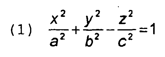
[0012] Both hyperboloids are hyperboloids of revolution of one sheet. These hyperboloids of revolution are defined as
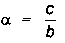
whereby a = b. The opening of the hyperbola, resp. the angle α of the asymptote is defined as
[0013] For the present case of a core member, where a = b these values can be calculated on the basis of the parameters given below.
[0014] In architecture, hyperboloids are known since the 19th century and in modern time some chimneys of nuclear power plants have also the shape of a hyperboloid.
[0015] As follows from Fig. 4, the hyperbolic shaped anchorage surface 2 has the advantage to require a minimal removal of the wall of the root canal, causing its minimal weakening.
[0016] The hyperbolic shape of surface 3 allows a better transmittal of the forces bearing on the crown to the core member.
[0017] It is understood that the values of a = b, and c for crown surface 3 are not necessarily the same as for anchorage surface 2.
[0018] As examples the following values for the greatest diameter R5 of ring face 6 and the smallest diameter R1 of the crown surface 3 and R2 of anchorage surface 2 are as follows:
[0019] The distance D1 between the beginning of the transfer part 5 and the ring face 6 can be 1.5 - 3 mm, and D2 between the ring face 6 and the end of the core member can be 1.5 - 3 mm.
[0020] The post 7 comprises a cylindrical part 8 to be received in bore 4 of the core member, followed by an anchorage part 9, which surface can also have a hyperbolic shape with the following values, where a = b:
[0022] The hyperbolic surfaces of the crown and anchoring part and of the post allow the optimal distribution of pressure or stress and prevents post, core member or root fractures.
[0023] In Fig. 4 the assembled core member and post is shown cemented into the root canal 11 of tooth 12.
[0024] The whole assembly comprises a calibrated drill or reamer 13 with reaming or drilling part 2D having the same shape as the core member part 2 for giving the root canal the hyperbolic shape which corresponds to the shape of the anchorage part of the core member and a calibrated drill or reamer 14 which drilling or reaming part 9D corresponds to the anchorage part 9 of the post.
[0025] The assembly of the invention allows for multiple ways of application:
- 1) The post can be fixed and cemented into the core member prior to insertion in the root canal, thereby it is possible to adjust it's length, resp. to have the same length as the core member in the crown part.
- 2) The post can be inserted first within the root canal and the core member is then sledded down the post till it reaches it's prepared seat in the upper part of the root canal.
- 3) The core member can be cemented first in the root canal and the post can be sledded through bore 4 into the root canal and the cylindrical part 8 of the post is - after adjusting its length - cemented within bore 4.
- 4) In some cases, the post can be used alone, without using the core member in teeth having particular roots or multi roots.
[0026] Although it is possible to produce the core member and the post of metal, usually stainless steel, as known in the prior art, it is preferable to produce the said parts of glass fibre reinforced composite material, for example as disclosed in US-A-6 402 519 to the same applicant.
1. Tooth root channel anchorage assembly, comprising a core member (1) to be fixed within
the tooth root channel (11) and a post (7) to be inserted into the core member, the
core member having a throughgoing bore (4), characterised in that the core member comprises a crown part (3) and an anchorage part (2) to be fixed
within the root canal, the surface of the anchorage part (2) having a substantially
hyperbolic form.
2. Assembly according to claim 1, characterised in that the crown part (3) of the core member (1) comprises a surface (5) which has a substantially
hyperbolic form.
3. Assembly according to claim 1 or 2, characterised in that the post (7) has a cylindrical part (8) fitting slidably into the bore (4) of the
core member (1), which cylindrical part is followed by a post anchorage part, which
surface (9) has a hyperbolic form.
4. Assembly according to any of claims 1 to 3, characterised in that the core member and the post are made of fibre glass reinforced composite material.
5. Assembly according to any of claims 1 to 4,
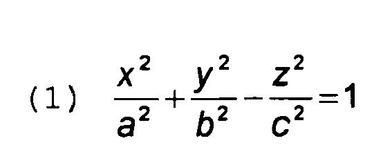
characterised in that the hyperboloid is a hyperboloid of revolution of one sheet, according to the formula:
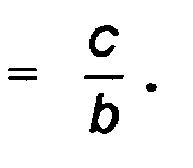
whereby a = b, and the asymptote is defined as having an angle
characterised in that the hyperboloid is a hyperboloid of revolution of one sheet, according to the formula:
whereby a = b, and the asymptote is defined as having an angle
6. Assembly according to claim 5, wherein the core member has the following values:
a = b
the greatest diameter R5 of the core member = 3 - 5 mm, the smallest diameter R1 of the crown surface = 2 - 4 mm, the smallest diameter R2 of the anchorage surface = 1.5 - 3 mm, the distance D1 between the beginning of the hyperbolic surface 5 and the greatest diameter R5 = 1.5 - 3 mm, and the distance D2 between the greatest diameter R5 and the end of the anchorage part R2 = 1.5 - 3 mm.
7. Assembly according to any of claims 5 to 6, wherein the post has the following values:
a = b
the diameter R3 of the cylindrical part 8 = 1.3 - 1.7 mm, the diameter R4 of the end of the post = 0.3 - 0.7 mm, the distance D3 between R3 and R4 = 8 - 12 mm.
a = b
the diameter R3 of the cylindrical part 8 = 1.3 - 1.7 mm, the diameter R4 of the end of the post = 0.3 - 0.7 mm, the distance D3 between R3 and R4 = 8 - 12 mm.
8. Assembly according to any of claims 1 to 7, characterised in that it further comprises a drill or reamer (13) having the same drilling or reaming surface
(D2) as the anchorage part (2) of the core member (1) and a drill or reamer (14) having
the same drilling or reaming surface (D9) as the post part (9) to be inserted into
the root canal.
1. Zahnwurzelkanal-Verankerungsanordnung mit einem im Zahnwurzelkanal (11) zu fixierenden
Kern (1) und einem in den Kern einzuführenden Stift (7), wobei der Kern eine durchgehende
Bohrung (4) aufweist, dadurch gekennzeichnet, dass der Kern einen Kronenteil (3) und einen im Wurzelkanal zu fixierenden Verankerungsteil
(2) aufweist, wobei die Oberfläche des Verankerungsteils (2) eine im Wesentlichen
hyperbolische Form aufweist.
2. Anordnung nach Anspruch 1, dadurch gekennzeichnet, dass der Kronenteil (3) des Kerns (1) eine Oberfläche (5) mit im Wesentlichen hyperbolischer
Form aufweist.
3. Anordnung nach Anspruch 1 oder 2, dadurch gekennzeichnet, dass der Stift (7) einen zylindrischen Teil (8) aufweist, der in die Bohrung (4) des Kerns
(1) einschiebbar ist, welcher zylindrische Teil in einen Stiftverankerungsteil übergeht,
dessen Oberfläche (9) eine hyperbolische Form aufweist.
4. Anordnung nach einem der Ansprüche 1 bis 3, dadurch gekennzeichnet, dass der Kern und der Stift aus glasfaserverstärktem Verbundmaterial hergestellt sind.
5. Anordnung nach einem der Ansprüche 1 bis 4, dadurch gekennzeichnet, dass das Hyperboloid ein einschaliges Rotationshyperboloid mit der Formel:
ist, wobei a = b und die Asymptote mit einem Winkel

definiert ist.
ist, wobei a = b und die Asymptote mit einem Winkel
definiert ist.
6. Anordnung nach Anspruch 5, wobei der Kern folgende Werte aufweist:
a = b
grösster Durchmesser R5 des Kerns = 3 - 5 mm, kleinster Durchmesser R1 der Kronenfläche = 2 - 4 mm, kleinster Durchmesser R2 der Verankerungsfläche = 1,5 - 3 mm, Abstand D1 zwischen dem Anfang der hyperbolischen Fläche 5 und dem grössten Durchmesser R5 = 1,5 - 3 mm und Abstand D2 zwischen dem grössten Durchmesser R5 und dem Ende des Verankerungsteils R2 = 1,5 - 3 mm.
7. Anordnung nach einem der Ansprüche 5 bis 6, wobei der Stift folgende Werte aufweist:
a = b
Durchmesser R3 des zylindrischen Teils 8 = 1,3 - 1,7 mm, Durchmesser R4 des Stiftendes = 0,3 - 0,7 mm, Abstand D3 zwischen R3 und R4 = 8 - 12 mm.
a = b
Durchmesser R3 des zylindrischen Teils 8 = 1,3 - 1,7 mm, Durchmesser R4 des Stiftendes = 0,3 - 0,7 mm, Abstand D3 zwischen R3 und R4 = 8 - 12 mm.
8. Anordnung nach einem der Ansprüche 1 bis 7, dadurch gekennzeichnet, dass sie weiter einen Bohrer oder eine Reibahle (13) mit der gleichen Bohr- oder Reibfläche
(D2) wie der Verankerungsteil (2) des Kerns (1) und einen Bohrer oder eine Reibahle
(14) mit der gleichen Bohr- oder Reibfläche (D9) wie der in den Wurzelkanal einzuführende
Stiftteil (9) umfasst.
1. Ensemble d'ancrage pour canaux radiculaires dentaires, comprenant un noyau (1) destiné
à être fixé dans le canal radiculaire dentaire (11) et un tenon (7) destiné à être
introduit dans le noyau, le noyau présentant un alésage traversant (4), caractérisé en ce que le noyau comprend une partie couronne (3) et une partie d'ancrage (2) destinée à
être fixée dans le canal radiculaire, la surface de la partie d'ancrage (2) ayant
une forme essentiellement hyperbolique.
2. Ensemble selon la revendication 1, caractérisé en ce que la partie couronne (3) du noyau (1) présente une surface (5) qui a une forme essentiellement
hyperbolique.
3. Ensemble selon la revendication 1 ou 2, caractérisé en ce que le tenon (7) a une partie cylindrique (8) insérable par coulissement dans l'alésage
(4) du noyau (1), laquelle partie cylindrique est prolongée d'une partie d'ancrage
du tenon dont la surface (9) présente une forme hyperbolique.
4. Ensemble selon l'une quelconque des revendications 1 à 3, caractérisé en ce que le noyau et le tenon sont fabriqués en matériau composite renforcé de fibre de verre.
5. Ensemble selon l'une quelconque des revendications 1 à 4, caractérisé en ce que l'hyperboloïde est un hyperboloïde de révolution à une nappe selon la formule:

où a = b, et l'asymptote est définie comme ayant un angle

où a = b, et l'asymptote est définie comme ayant un angle
6. Ensemble selon la revendication 5, où le noyau a les valeurs suivantes:
a = b
le plus grand diamètre R5 du noyau = 3 - 5 mm, le plus petit diamètre R1 de la surface de la couronne = 2 - 4 mm, le plus petit diamètre R2 de la surface d'ancrage = 1,5 - 3 mm, la distance D1 entre le début de la surface hyperbolique 5 et
le plus grand diamètre R5 = 1,5 - 3 mm et la distance D2 entre le plus grand diamètre R5 et l'extrémité de la partie d'ancrage R2 = 1,5 - 3 mm.
7. Ensemble selon l'une quelconque des revendications 5 à 6, où le tenon a les valeurs
suivantes:
a = b
le diamètre R3 de la partie cylindrique 8 = 1,3 - 1,7 mm, le diamètre R4 de l'extrémité du tenon = 0,3 - 0,7 mm, la distance D3 entre R3 et R4 = 8 - 12 mm.
a = b
le diamètre R3 de la partie cylindrique 8 = 1,3 - 1,7 mm, le diamètre R4 de l'extrémité du tenon = 0,3 - 0,7 mm, la distance D3 entre R3 et R4 = 8 - 12 mm.
8. Ensemble selon l'une quelconque des revendications 1 à 7, caractérisé en ce qu'elle comprend en outre un foret ou alésoir (13) ayant la même superficie de forage
ou d'alésage (D2) que la partie d'ancrage (2) du noyau (1) et un foret ou alésoir
(14) ayant la même superficie de forage ou d'alésage (D9) que la partie du tenon (9)
destinée à être insérée dans le canal radiculaire.
REFERENCES CITED IN THE DESCRIPTION
This list of references cited by the applicant is for the reader's convenience only. It does not form part of the European patent document. Even though great care has been taken in compiling the references, errors or omissions cannot be excluded and the EPO disclaims all liability in this regard.
Patent documents cited in the description