| (19) |
 |
|
(11) |
EP 2 049 053 B1 |
| (12) |
EUROPEAN PATENT SPECIFICATION |
| (45) |
Mention of the grant of the patent: |
|
18.11.2009 Bulletin 2009/47 |
| (22) |
Date of filing: 27.07.2007 |
|
| (51) |
International Patent Classification (IPC):
|
| (86) |
International application number: |
|
PCT/EP2007/057782 |
| (87) |
International publication number: |
|
WO 2008/015175 (07.02.2008 Gazette 2008/06) |
|
| (54) |
METHOD AND APPARATUS FOR CALCULATING A LASER SHOT FILE FOR USE IN AN EXCIMER LASER
VERFAHREN UND GERÄT ZUR BERECHNUNG EINES LASERSCHUSSFILES ZUR VERWENDUNG IN EINEM
EXCIMER-LASER
PROCÉDÉ ET APPAREIL POUR CALCULER UN FICHIER DE DÉCHARGE LASER POUR UNE UTILISATION
DANS UN LASER À EXCIMÈRE
|
| (84) |
Designated Contracting States: |
|
DE ES FR GB IT |
| (30) |
Priority: |
02.08.2006 DE 102006036085
|
| (43) |
Date of publication of application: |
|
22.04.2009 Bulletin 2009/17 |
| (73) |
Proprietor: Technolas Perfect Vision GmbH |
|
80992 München (DE) |
|
| (72) |
Inventor: |
|
- HEGELS, Ernst
85551 Kirchheim (DE)
|
| (74) |
Representative: Vossius & Partner |
|
Siebertstraße 4
81675 München
81675 München (DE) |
| (56) |
References cited: :
WO-A-01/24688
WO-A-2004/095187
US-A- 5 928 221
|
WO-A-2004/041104
WO-A-2005/007002
US-A- 6 090 100
|
|
| |
|
|
|
|
| |
|
| Note: Within nine months from the publication of the mention of the grant of the European
patent, any person may give notice to the European Patent Office of opposition to
the European patent
granted. Notice of opposition shall be filed in a written reasoned statement. It shall
not be deemed to
have been filed until the opposition fee has been paid. (Art. 99(1) European Patent
Convention).
|
Field of the invention
[0001] The present invention relates to a method and apparatus for calculating a laser shot
file for use in an excimer laser in particular using a dithering algorithm. The invention
is specifically, suitable for applying the laser shot file when performing a laser
treatment of an eye or when producing a customized contact lens or an intraocular
lens (IOL) by laser ablation.
Description of the related art
[0002] US 6,090,100 relates to an excimer laser system for correction of vision with reduced thermal
effects. It specifically relates to an apparatus and method for controlling the excimer
laser system for removing tissue from the eye to perform various types of corrections,
such as myopia, hyperopia, and astigmatism correction. In one disclosed embodiment,
the excimer laser system provides a relatively large spot size which provides a relatively
large coverage of treatment area per shot. While using such large spot sizes, the
shots are generally not "adjacent" to each other but instead overlap to generate the
desired degree of ablation at a particular point. For calculating the result of the
overlapping shots, an algorithm is used. In one method of calculating treatment patterns
using large, fixed spot sizes distributed throughout the treatment area, a dithering
algorithm is used. Specific reference is made to a rectangular dithering, circular
dithering and a line-by-line oriented dithering. Using any variety of shot dithering
methods, an array of shots is created for a fixed spot size spread over a treatment
area to correct to the desired degree of ablation. For the respective array, a grid
is used with a constant grid width between individual grid positions. With the known
dither methods, the shape of the desired ablation profile, which usually is a continuous
profile, has to be transferred into a whole-numbered discrete density distribution.
Here, the continuous profile represents a planned ablation and the whole-numbered
discrete density distribution represents a series of ablating flying spot laser pulses.
The residual structure, i.e., the difference between the planned and the achieved
profile, has to be minimised. Exact solutions can principally be found numerically
but not in a reasonable time. Therefore, for this purpose, dither algorithms are used.
The profile is discretised on a given grid. Using a cost function or merit function
the algorithm decides for each position of the grid whether to place a shot or not.
For this decision, usually only a few neighbouring positions of the grid are taken
into account. This dither algorithm saves calculation time without the need that the
real size of the spot is taken into account. It is sufficient to know the shot volume
which is ablated with one laser shot. However, under certain conditions, the known
dither algorithms produce artefacts in parts of the profile, e.g., in low-density
regions where the next neighbouring shot is too far away. Artefacts may also be produced
in high-density regions where at nearly every position, a shot is placed. The positions
with no shot also have too large a distance for the assumption that only a few neighbour
positions are necessary.
[0003] As regards the general background of dithering algorithms, reference is made to
US 6,271,936 B1, which relates to the field of digital image processing. It particularly relates
to a method for digitally multitoning a continous-tone image using error diffusion,
dithering and over-modulation methods. Reference is made to the problem that an artefact
may occur like worms which are formed when the black or white output pixels appear
to string together in an area that should be otherwise uniform. Wherein this US patent
gives a detailed description of these known methods, it is related to a completely
different technical field. Among other differences, known laser printer systems are
using a respective fixed resolution given as a number of dots per inch, i.e., a higher
number of dots per inch results in a better resolution. Moreover, a known laser printer
has no problem with overlapping and touching dots because this does not result in
an additional blackening when hitting a. point twice or more often. Rather, to produce
an image, a certain local area of the image having a certain grey level can be created
by applying a corresponding number of dots in this local arena.
Summary of the invention
[0004] The object underlying the present invention is to provide a method and apparatus
for calculating a laser shot file for use in a refractive excimer laser, wherein the
difference between the planned and the achieved profile is minimised. This object
is solved with the features of the claims.
A desired ablation profile for correcting for example myopia has a maximum shot density
in the central part of the treatment zone whereas a minimum shot density is present
along the circumferential border of the treatment zone. Thus, the number of laser
shots to be applied to the central part of the treatment zone is higher than in other
sub-areas in particular along the border of the treatment zone.
[0005] For the correction of, for example, hyperopia the minimum shot density is present
in the central part of the treatment zone. On the other hand, the ablation profile
requires a higher number of laser shots along a circumferential border of the treatment
zone.
[0006] The invention is generally applicable for any ablation profile, wherein sub-areas
having different shot densities are investigated in order to determine any sub-area
having a maximum shot density and/or any sub-area having a minimum shot density.
[0007] The general concept of the present invention is based on the idea to adapt the dither
algorithm which is used for placing laser shots of the excimer laser when discretizing
a given ablation profile on a given grid. Using a cost function the dither algorithm
decides for each position of a grid whether to place a shot. More specifically, the
shot density for obtaining a predetermined desired ablation profile is calculated
first. Depending on the calculated shot density of the desired ablation profile, the
dither algorithm is adapted by using a dynamic threshold value being used in a cost
function for the shot calculation.
[0008] According to a preferred embodiment of the present invention, the threshold value
is selected from at least two different threshold values depending on the minimum
shot density and/or maximum shot density of the desired ablation profile. Generally,
for a desired ablation profile having low shot densities, a lower threshold value
is used. For a desired ablation profile having high shot densities, a higher threshold
value is used.
[0009] According to a preferred embodiment of the present invention, a first threshold value
is a value within the range of 0% to 20% of the maximum shot density of the ablation
profile. Alternatively or in addition a second threshold value is a value within the
range of 20% to 80% of the maximum shot density. Alternatively or in addition a third
threshold value is a value within the range of 80% to 100% of the maximum shot density.
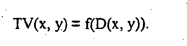
[0010] According to a further preferred embodiment of the present invention, more than three
different threshold values are used and more preferably the threshold value "TV(x,
y)" is related to the shot density "D(x, y)" according to the following equation (1):

More preferably, there is a linear relationship between the threshold value "TV(x,
y)" and "D(x, y)" according to the following equation (2):

wherein "a" is a positive factor within the range of 0 < a ≤ 1.5 and wherein "x" and
"y" are the coordinates of the grid position for which the calculation is made.
[0011] Preferably, the threshold value is set for each grid position in correspondence to
the density function. More preferably, the threshold value is set to a value equal
to or nearby the value of the density function at a respective grid position.
[0012] The threshold value is preferably at least a value within the range of 80% to 110%,
more preferably of 90% to 100% of the value of the density function at a respective
grid position. Thus, the factor "a" of equation (1) is a value preferably within the
range of 0.8 to 1.1, more preferably of 0.9 to 1.0. Best results can be achieved with
a=1.
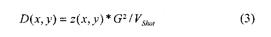
[0013] A local shot density D(x, y) within a sub-area around a grid position P(x, y) is
calculated from an ablation profile z(x, y) within the respective sub-area using the
ablation volume of a single laser shot V
Shot and a given width G using following equation:
[0014] According to a preferred embodiment, a dither algorithm is used for calculating the
placement of the laser shots of the excimer laser on grid positions. The dither algorithm
is adapted to the desired ablation profile by determining the optimised grid width
for the grid to be used for the dither algorithm. For a more detailed description
of this aspect to optimize the grid width, reference is made to the co-pending patent
application of the present applicant with the title "Method and apparatus for calculating
a laser shot file for use in a refractive excimer laser".
[0015] According to a preferred embodiment, with following equation the grid width is found
for a maximum value of the Profile z
max(x, y) and for a desired maximum density D
max (x, y):
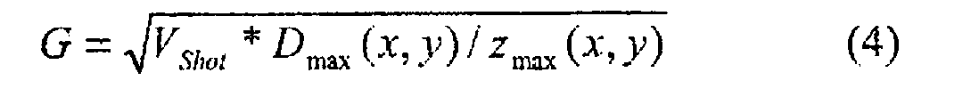
[0016] With equation 3 the local shot density around the minimum of the desired profile
is calculated with a given grid width. Preferably the grid width is calculated with
equation 4. The influence of the dynamic threshold is explained using two examples.
As a first example a treatment using a treatment zone of about 5.5mm for a desired
correction of +4dpt is selected. This hyperopia correction has the maximum of the
ablation along an annular portion circumfering the centre. The desired depth is approximately
26µm. About 445 laser shots are necessary to reach a result with a typical excimer
treatment laser. To get shot densities along the annular portion of about 18% a grid
width of 98µm is chosen. In this example an ablation is calculated using a constant
threshold. In a second example of an ablation the treatment zone is again 5.5mm and
the correction is +4dpt. The desired maximum depth is also about 26µm and about 445
laser shots are needed. For the second example, a dynamic threshold is used. The second
example shows the advantage to use a dynamic threshold when calculating the ablation.
[0017] According to a further preferred embodiment, a desired ablation profile is divided
into at least two ablation sub-profiles. Then for each ablation sub-profile, the respective
shot density is calculated and a respective grid width based on the respective calculated
density of the ablation sub-profile is determined. Each sub-profile is calculated
using the dynamic threshold. Thus, for a desired ablation profile where the contrast
is too high, i.e., a difference between the maximum shot density and the minimum shot
density is too high, the calculation of the laser shot file is made in two or more
runs preferably using different grid constants or grid widths for each respective
ablation sub-profile resulting in a corresponding laser shot file. Thereafter, the
two or more laser shot files can be combined in one single laser shot file.
[0018] According to the present invention, the calculated, placed laser shots are processed
in a further step of sorting to obtain a laser shot sequence. The sorting is performed
taking into consideration that any thermal effects should be avoided, i.e., two consecutive
laser shots are preferably placed on different grid positions in the treatment zone
which are at a distance from each other.
Brief description of the drawings
[0019] The invention will be further described by way of examples with reference to the
drawings, in which:
Fig. 1A is a diagram showing the location of laser spots for a first test using a
constant threshold value,
Fig. 1B is a diagram showing the planned and the achieved profile as a cross-section
along the horizontal axis of Fig. 1A,
Fig. 1C is a diagram showing the planned and the achieved profile as a cross-section
along the vertical axis of Fig. 1A,
Fig. 2A is a diagram showing the location of laser spots for a second test using a
dynamic threshold value according to a preferred embodiment of the present invention,
Fig. 2B is a diagram showing the planned and the achieved profile as a cross-section
along the horizontal axis of Fig. 2A,
Fig. 2C is a diagram showing the planned and the achieved profile as a cross-section
along the vertical axis of Fig. 2A,
Fig. 3 shows a flow diagram with a calculation of laser pulse patterns with a dither
algorithm, and
Fig. 4 shows an example of a sub-grid with weighting factors usable for weighting
neighbouring error values.
Detailed description of the preferred embodiment
[0020] Figs. 1A, 1B and 1C show the simulated calculation of a laser shot tile for use in
an excimer laser for the correction of hyperopia with a value of about +4 dioptres,
using a typical excimer laser for refractive treatments, within a treatment zone having
a diameter of 5.5 mm and using a laser spot having a diameter of 1 mm. In this simulated
first test, the grid width is 98µm. Thus, the distance between two neighbour grid
points is 98µm. In this example, the grid points are arranged in rows and columns.
In total, 445 laser shots are used for achieving the ablation. Depending on the ablated
volume of a single shot the resulting treatment is expected to have a refraction of
said about +4 dioptres. The diagram of Fig. 1A shows the respective centre position
of each of the 445 laser shots which is related to one of the grid positions each
marked with a "+"-sign. In the upper right corner of Fig. 1A, the grid is schematically
shown having a grid width of 98µm. Each of the shown laser shot centre positions are
arranged on a grid point of this grid. The diagram of Fig. 1B shows, as a dashed line,
the desired ablation profile, i.e., the ablation depth in µm with respect to a respective
X-position. The ablation depth is approximately 26µm in an annular portion of the
treatment zone at about the x-positions -2 and +2 and is smaller in the centre portion
and at both sides. The ablation depth is almost zero in the centre portion. It further
shows the simulated resulting ablation profile as a continuous line as a cross-section
taken along the horizontal axis through the point 0-0 in Fig. 1A. Similarly, Fig.
1C shows the desired ablation profile as a dashed line which is taken as a cross-section
along the vertical axis through the point 0-0 in Fig. 1A. Fig. 1C further shows the
resulting ablation profile as a continuous line taken as a cross-section along the
vertical axis through point 0-0 of Fig. 1A. In Fig. 1 the average shot density inside
the treatment zone, having in this example a diameter of 5.5mm, is about 18% (Figure
1A). The respective centre positions of the laser shots are placed within a range
of ± 2.7mm in the X-direction and ± 2.7mm in the Y-direction.
[0021] Figs. 2A, 2B and 2C show the results of a similar second test as in Figs. 1A, 1B
and 1C except for using a dynamic threshold. More specifically in this test the shot
density D (x, y) has been used as the threshold value TV (x, y). Thus, the factor
"a" in the above equation (2) is selected as a=1.
[0022] The use of a constant threshold value for the first test causes artefacts like the
linewise arrangement of laser shot positions in the lower part of the ablation (Figure
1A). For example, as shown, several laser shots are provided at grid positions which
are arranged along a horizontal bottom line at a closer distance. Further laser shots
are provided at grid positions which arc arranged at a larger distance from this horizontal
bottom line. Thus, the laser shots are not provided in an equal manner resulting in
a deviation from the desired ablation profile (see Fig. 1C).
[0023] A comparison of the Figures for the first test and the second test shows that the
resulting ablation profile in the second test is better, i.e., the curve of the resulting
ablation profile better follows to the curve of the desired ablation profile (see
Figs. 2B and 2C). In particular, Fig. 1C shows that the resulting ablation profile
deviates from the desired ablation profile, i.e., there is a shift with respect to
the right part of the desired ablation profile. The dither algorithm produces artefacts
in parts of the resulting ablation profile which may depend on the order of the calculation
of the laser shots for respective grid positions. In regions with gradients in shot
density, the shots are shifted. The shift depends on the depth of the desired ablation.
Additionally, artefacts called worms may be introduced.
[0024] By using a dither algorithm, the input parameters are the shot volume of a laser
shot and the desired ablation profile. There is no need to take the beam diameter
into account as the dither algorithm works independently therefrom. The dither algorithm
provides a laser shot file as an output. More specifically, the dither algorithm is
used for the placement of laser shots of the excimer laser on grid positions. Preferably,
a cost function is used for deciding for each grid position whether a laser shot is
placed or not. Herein, preferably the decision is made with regard to whether one
or more laser shot(s) is (are) placed at a grid position(s) within the neighbourhood
of the given grid position. Preferably, a dither algorithm is used as disclosed in
US 6,090,100.
[0025] In the following a preferred dithering algorithm will be described with reference
to Figure 3 which shows a flow chart representing an example for the error diffusion.
This dither algorithm is based on the concept of error diffusion. Prior to the step
of error diffusion, the desired ablation profile is calculated based, e.g., on the
desired correction of a patient's eye or the modification of contact lenses or of
IOLs. This profile is stored within a grid having a specific grid width. For example,
such a grid has 256 x 256 values which covers an area of 15
2 mm
2. The error diffusion may be started in one edge within that grid and follows it line
by line.
[0026] In a first step S1, the ablation profile and the dynamic threshold is determined
using equation 1 and the active dither position is set to a point in one of the edges
of the grid. Optionally, a desired grid width is calculated. Said active dither position
represents the actual position within the grid being processed.
[0027] In a next step S2, a desired ablation value for the active dither position is obtained.
In step S3 this desired ablation value is multiplied with a scaling factor f. The
scaling factor f takes into account the different size of laser pulse and the positioning
step, i.e., the grid width. More specifically, the scaling factor is calculated as
follows to get the desired shot density at this position (see equation 3):
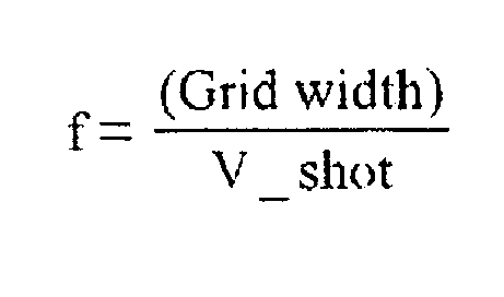
[0028] For the above-mentioned grid having 256 x 256 values covering an area of 15
2 mm
2, the grid width is 15 mm/256 = 58 µm. Thus, the area of the smallest square the laser
beam can be sent around is (58 µm)
2. Thus, the number of calculated pulses are reduced in order to take into account
for the overlapping of laser pulses.
[0029] In a next step S4, weighted neighbouring errors are added to the scaled desired ablation
value for the active dither position. These weighted neighbouring errors are preferably
the weighted sum of errors of adjacent grid points that have already been processed.
An example will be described later.
[0030] In a further step S5, a decision is made whether the obtained value is larger than
a predetermined threshold. Thus, the sum of the value for the respective grid point
and the weighted errors of adjacent grid points will be compared to this threshold
value. If the value is not larger than the dynamic threshold T (x, y) step S9 follows.
If the value is larger than the threshold, a laser pulse is set for this grid position
in step S6. One laser pulse is subtracted from said density value. Then in step S7
it is determined whether a new value is still larger than the threshold. In case the
new value is larger than the dynamic threshold in step S8, it is determined that an
error of shot overflow occurred. In other words, if at a grid position it would be
necessary to set more than laser pulse, the algorithm has to stop with an error. By
the use of grid width calculated with equation 4 this error can be avoided. In this
exemplary implementation of the error diffusion, a maximum of one laser pulse for
each grid position is allowed.
[0031] On the other hand, if the new value is not larger than a dynamic threshold in step
S9, this new value is stored as an error for this particular grid position. It will
be used when processing neighbouring positions for the calculation with respect to
further dither positions.
[0032] In the next step S10, it is decided whether the line is complete; if not, in step
S11 a next point in the same line is selected as an active position and the before-mentioned
processing is repeated. In case the line is complete, then in step S12 a decision
has to be made whether there is a new line; if yes, then in step S13 a first point
in the new line is selected as active position and the processing is repeated. Otherwise,
if there is no new line, the processing ends with step S14. The before-mentioned grid
point error represents the ablation error done at a particular grid point. For each
grid point processed, this error is the sum of desired ablation value plus the weighted
neighbouring errors minus the laser pulse ablation depth (if a laser pulse has been
set for that position).
[0033] Figure 4 shows an example for weighting of errors of neighbouring grid points. More
specifically, Figure 4 shows a sub-grid of 7 x 7 grid points, wherein the active dither
position is shown in the middle. In this case, the weighting function is determined
as 8/distance with a distance measured in units of grid points. The sum of the errors
will then be normalised by a division with 70.736 which is the sum of all weighting
factors used. As apparent from Figure 4, the white positions indicate grid position
not yet processed. Thus, before deciding whether a laser pulse has to be set at a
given grid position, the error induced while processing adjacent grid points has to
be added to the theoretical ablation value for that grid point. The errors of the
neighbouring grid points are not simply added but weighted due to their distance to
the active grid point. The respective weighting factors are shown in Figure 4. It
shall be noted that this is just one possible method for summing up the surrounding
errors, which is working fine.
[0034] It shall be noted that the above described dither algorithm is only one example for
using the present invention.
[0035] A laser shot sequence may be determined thereafter by using a separate sorting algorithm.
A sorting may be performed in order to avoid thermal effects. Thus, any two following
laser shots should preferably be placed at two grid positions at a distance from each
other. Preferably, every four shots a laser shot is placed in the same region as the
first shot.
[0036] The foregoing disclosure and description of the invention are illustrative and explanatory
thereof and changes in the construction and method of operation may be made without
departing from the scope of the invention.
1. A method for calculating a laser shot file for use in an excimer laser preferably
for performing a refractive laser treatment of an eye or for producing a customized
contact lens or an intraocular lens comprising the steps of providing information
with respect to a desired ablation profile and using a dither algorithm, wherein the
dither algorithm is adapted to the desired ablation profile by using a dynamic threshold
depending on a shot density of the desired ablation profile for calculating the laser
shot file.
2. The method of claims 1, further comprising the steps of using the dither algorithm
for discretizing the desired ablation profile on a given grid and deciding for each
grid position whether to place a laser shot of the excimer laser on said grid position.
3. The method of claim 2, wherein the dither algorithm is using a cost function for determining
for each grid position whether to place a laser shot of the excimer laser on said
grid position.
4. The method of any of the foregoing claims, further comprising the step of calculating
a shot density for obtaining the desired ablation profile and wherein said dynamic
threshold is defined depending on the calculated shot density of the desired ablation
profile.
5. The method of any of the foregoing claims, wherein at least two different threshold
values are used depending on the desired ablation profile.
6. The method of claim 5, wherein a first threshold value is used for a desired ablation
profile having low shot densities and/or a second threshold value is used for a desired
ablation profile having high shot densities, wherein said first threshold value is
lower than said second threshold value.
7. The method of claim 6, wherein the first threshold value is a value within a range
of 0% to 20% of a maximum shot density of the desired ablation profile and/or the
second threshold value is a value within a range of 20% to 80% of the maximum shot
density and/or a third threshold value is a value within a range of 80% to 100% of
the maximum shot density.
8. The method of any of the foregoing claims, wherein the threshold value TV(x, y) is
related to the shot density of the desired ablation profile D(x, y) according to the
equation:
9. The method of any of the foregoing claims, wherein the threshold value TV(x, y) is
linearly related to the shot density of the desired ablation profile D(x, y) according
to the following equation:
wherein a is a factor within the range of 0 < a ≤ 1.5, more preferably 0.8 ≤ a ≤ 1.1
and most preferably a=1.
10. The method of claim 9, wherein the threshold value is set to a value equal or nearby
the value of the shot density.
11. The method of any of the foregoing claims, wherein a grid width of the given grid
is ' determined based on the calculated shot density of the desired ablation profile.
12. The method of any of claims 2 to 11, wherein in the step of deciding whether to place
a shot on a given grid position a corresponding decision with regard to grid positions
in the neighborhood of the given grid position is taken into account.
13. The method of any of the foregoing claims further comprising the step of dividing
a desired ablation profile into at least two ablation sub-profiles, calculating the
shot density of each of said ablation sub-profiles, and determining a respective grid
width based on the respective calculated shot density of each of the ablation sub-profiles.
14. The method of any of claims 2 to 13 further comprising the step of sorting the calculated
placed laser shots.
15. The method of any of the foregoing claims wherein the excimer laser provides a laser
beam at a spot size fixed between 0.5 mm and 3.5 mm in diameter, preferably at a spot
size fixed between 1.0 to 2.0 mm in diameter.
16. An apparatus for calculating a laser shot file for use in an excimer laser preferably
for performing a refractive laser treatment of an eye or for producing a customized
contact lens or an intraocular lens comprising means for providing information with
respect to a desired ablation profile and using a dither algorithm, wherein the dither
algorithm is adapted to the desired ablation profile by using a dynamic threshold
depending on a shot density of the desired ablation profile for calculating the laser
shot file.
17. The apparatus of claim 16, further comprising when using the dither algorithm means
for discretizing the desired ablation profile on a given grid and means for deciding
for each grid position whether to place a laser shot of the excimer laser on said
grid position.
18. The apparatus of claim 17, wherein the dither algorithm is using a cost function for
determining for each grid position whether to place a laser shot of the excimer laser
on said grid position.
19. The apparatus of any of claims 16 to 18, further comprising means for calculating
a shot density for obtaining the desired ablation profile and wherein said dynamic
threshold is defined depending on the calculated shot density of the desired ablation
profile.
20. The apparatus of any of claims 16 to 19, further comprising means for selecting at
least two different threshold values depending on the desired ablation profile.
21. The apparatus of claim 20, wherein a first threshold value is selected for a desired
ablation profile having low shot densities and/or a second threshold value is selected
for a desired ablation profile having high shot densities, wherein said first threshold
value is lower than said second threshold value.
22. The apparatus of claim 21, wherein the first threshold value is a value within a range
of 0% to 20% of a maximum shot density of the desired ablation profile and/or the
second threshold value is a value within a range of 20% to 80% of the maximum shot
density and/or a third threshold value is a value within a range of 80% to 100% of
the maximum shot density.
23. The apparatus of any of claims 16 to 22, further comprising means for determining
the threshold value TV(x, y) in relation to the shot density of the desired ablation
profile D(x, y) according to the equation:
24. The apparatus of any of claims 16 to 22, further comprising means for determining
the threshold value TV(x, y) as a linear relationship to the shot density of the desired
ablation profile D(x, y) according to the following equation:
wherein a is a factor within the range of 0 < a ≤ 1.5, more preferably 0.8 ≤ a ≤ 1.1
and most preferably a = 1.
25. The apparatus of claim 24, further comprising means for setting the threshold value
to a value equal or nearby the value of the shot density.
26. The apparatus of any of claims 16 to 25, further comprising means for determining
a grid width of the given grid based on the calculated shot density of the desired
ablation profile.
27. The apparatus of any of claims 17 to 26, wherein said means for deciding whether to
place a shot on a given grid position is using information regarding a corresponding
decision with regard to grid positions in the neighborhood of the given grid position.
28. The apparatus of any of claims 16 to 27 further comprising means for dividing a desired
ablation profile into at least two ablation sub-profiles, means for calculating the
shot density of each of said ablation sub-profiles, and means for determining a respective
grid width based on the respective calculated shot density of each of the ablation
sub-profiles.
29. The apparatus of any of claims 17 to 28 further comprising means for sorting the calculated
placed laser shots.
30. The apparatus of any of claims 16 to 29, wherein the excimer laser provides a laser
beam at a spot size fixed between 0.5 mm and 3.5 mm in diameter, preferably at a spot
size fixed between 1.0 to 2.0 mm in diameter.
1. Verfahren zur Berechnung einer Laserschussdatei zur Verwendung in einem Excimer-Laser
vorzugsweise zur Durchführung einer refraktiven Laserbehandlung eines Auges oder zur
Herstellung einer kundenspezifischen Kontaktlinse oder einer Intraokularlinse, das
die Schritte aufweist: Bereitstellen von Informationen bezüglich eines gewünschten
Ablationsprofils und Verwenden eines Dithering-Algorithmus, wobei der Dithering-Algorithmus
durch Verwendung einer dynamischen Schwelle zur Berechnung der Laserschussdatei an
das gewünschte Ablationsprofil in Abhängigkeit von der Schussdichte des gewünschten
Ablationsprofils angepasst wird.
2. Verfahren nach Anspruch 1, das ferner die Schritte aufweist: Verwenden des Dithering-Algorithmus
zum Diskretisieren des gewünschten Ablationsprofils auf ein gegebenes Gitter und Entscheiden
für jede Gitterposition, ob ein Laserschuss des Excimer-Lasers auf dieser Gitterposition
platziert werden soll.
3. Verfahren nach Anspruch 2, wobei der Dithering-Algorithmus eine Kostenfunktion verwendet,
um für jede Gitterposition festzustellen, ob ein Laserschuss des Excimer-Lasers auf
die Gitterposition platziert werden soll.
4. Verfahren nach einem der vorhergehenden Ansprüche, das ferner den Schritt des Berechnens
einer Schussdichte zum Erhalten des gewünschten Ablationsprofils aufweist und wobei
die dynamische Schwelle abhängig von der berechneten Schussdichte des gewünschten
Ablationsprofils definiert wird.
5. Verfahren nach einem der vorhergehenden Ansprüche, wobei abhängig vom gewünschten
Ablationsprofil mindestens zwei unterschiedliche Schwellenwerte verwendet werden.
6. Verfahren nach Anspruch 5, wobei ein erster Schwellenwert für ein gewünschtes Ablationsprofil
mit niedrigen Schussdichten verwendet wird, und/oder ein zweiter Schwellenwert für
ein gewünschtes Ablationsprofil mit hohen Schussdichten verwendet wird, wobei der
erste Schwellenwert niedriger als der zweite Schwellenwert ist.
7. Verfahren nach Anspruch 6, wobei der erste Schwellenwert ein Wert innerhalb eines
Bereichs von 0% bis 20% einer maximalen Schussdichte des gewünschten Ablationsprofils
ist, und/oder der zweite Schwellenwert ein Wert innerhalb eines Bereichs von 20% bis
80% der maximalen Schussdichte ist, und/oder ein dritter Schwellenwert ein Wert innerhalb
eines Bereichs von 80% bis 100% der maximalen Schussdichte ist.
8. Verfahren nach einem der vorhergehenden Ansprüche, wobei der Schwellenwert TV(x,y)
mit der Schussdichte des gewünschten Ablationsprofils D(x,y) gemäß der folgenden Gleichung
in Beziehung steht:
9. Verfahren nach einem der vorhergehenden Ansprüche, wobei der Schwellenwert TV(x,y)
mit der Schussdichte des gewünschten Ablationsprofils D(x,y) gemäß der folgenden Gleichung
linear in Beziehung steht:
wobei a ein Faktor innerhalb des Bereichs von 0<a≤1,5, bevorzugter von 0,8≤a≤1, und
am bevorzugtesten a=1 ist.
10. Verfahren nach Anspruch 9, wobei der Schwellenwert auf einen Wert eingestellt wird,
der gleich oder nahe dem Wert der Schussdichte ist.
11. Verfahren nach einem der vorhergehenden Ansprüche, wobei eine Gitterweite des gegebenen
Gitters beruhend auf der berechneten Schussdichte des gewünschten Ablationsprofils
bestimmt wird.
12. Verfahren nach einem der Ansprüche 2 bis 11, wobei im Entscheidungsschritt, ob ein
Schuss auf eine gegebene Gitterposition platziert werden soll, eine entsprechende
Entscheidung hinsichtlich der Gitterpositionen in der Nachbarschaft der gegebenen
Gitterposition berücksichtigt wird.
13. Verfahren nach einem der vorhergehenden Ansprüche, das ferner den Schritt aufweist:
Unterteilen eines gewünschten Ablationsprofils in mindestens zwei Ablationsteilprofile,
Berechnen der Schussdichte jedes der Ablationsteilprofile und Festlegen einer jeweiligen
Gitterweite beruhend auf der jeweiligen berechneten Schussdichte jedes der Ablationsteilprofile.
14. Verfahren nach einem der Ansprüche 2 bis 13, das ferner den Schritt des Sortierens
der berechneten platzierten Laserschüsse aufweist.
15. Verfahren nach einem der vorhergehenden Ansprüche, wobei der Excimer-Laser einen Laserstrahl
mit einer festen Fleckgröße zwischen 0,5 mm und 3,5 mm Durchmesser, vorzugsweise mit
einer festen Fleckgröße zwischen 1,0 und 2,0 mm Durchmesser liefert.
16. Vorrichtung zur Berechnung einer Laserschussdatei zur Verwendung in einem Excimer-Laser
vorzugsweise zur Durchführung einer refraktiven Laserbehandlung eines Auges oder zur
Herstellung einer kundenspezifischen Kontaktlinse oder einer Intraokularlinse, die
eine Einrichtung zum Bereitstellen von Informationen bezüglich eines gewünschten Ablationsprofils
und zum Verwenden eines Dithering-Algorithmus aufweist, wobei der Dithering-Algorithmus
durch Verwendung einer dynamischen Schwelle zur Berechnung der Laserschussdatei an
das gewünschte Ablationsprofil in Abhängigkeit von der Schussdichte des gewünschten
Ablationsprofils angepasst wird.
17. Vorrichtung nach Anspruch 16, die ferner, wenn der Dithering-Algorithmus verwendet
wird, eine Einrichtung zum Diskretisieren des gewünschten Ablationsprofils auf ein
gegebenes Gitter und eine Einrichtung zum Entscheiden für jede Gitterposition aufweist,
ob ein Laserschuss des Excimer-Lasers auf dieser Gitterposition platziert werden soll,
aufweist.
18. Vorrichtung nach Anspruch 17, wobei der Dithering-Algorithmus eine Kostenfunktion
verwendet, um für jede Gitterposition festzustellen, ob ein Laserschuss des Excimer-Lasers
auf die Gitterposition platziert werden soll.
19. Vorrichtung nach einem der Ansprüche 16 bis 18, die ferner eine Einrichtung zum Berechnen
einer Schussdichte zum Erhalten des gewünschten Ablationsprofils aufweist und wobei
die dynamische Schwelle abhängig von der berechneten Schussdichte des gewünschten
Ablationsprofils definiert wird.
20. Vorrichtung nach einem der Ansprüche 16 bis 19, die ferner eine Einrichtung aufweist,
um abhängig vom gewünschten Ablationsprofil mindestens zwei unterschiedliche Schwellenwerte
auszuwählen.
21. Vorrichtung nach Anspruch 20, wobei ein erster Schwellenwert für ein gewünschtes Ablationsprofil
mit niedrigen Schussdichten ausgewählt wird, und/oder ein zweiter Schwellenwert für
ein gewünschtes Ablationsprofil mit hohen Schussdichten ausgewählt wird, wobei der
erste Schwellenwert niedriger als der zweite Schwellenwert ist.
22. Vorrichtung nach Anspruch 21, wobei der erste Schwellenwert ein Wert innerhalb eines
Bereichs von 0% bis 20% einer maximalen Schussdichte des gewünschten Ablationsprofils
ist, und/oder der zweite Schwellenwert ein Wert innerhalb eines Bereichs von 20% bis
80% der maximalen Schussdichte ist, und/oder ein dritter Schwellenwert ein Wert innerhalb
eines Bereichs von 80% bis 100% der maximalen Schussdichte ist.
23. Vorrichtung nach einem der Ansprüche 16 bis 22, die ferner eine Einrichtung zum Bestimmen
des Schwellenwerts TV(x,y) in Bezug auf die Schussdichte des gewünschten Ablationsprofils
D(x,y) gemäß der Gleichung aufweist:
24. Vorrichtung nach einem der Ansprüche 16 bis 22, die ferner eine Einrichtung zum Bestimmen
des Schwellenwerts TV(x,y) als eine lineare Beziehung zur Schussdichte des gewünschten
Ablationsprofils D(x,y) gemäß der folgenden Gleichung aufweist:

wobei a ein Faktor innerhalb des Bereichs von 0<a≤1,5, bevorzugter von 0,8≤a≤1,1 und
am bevorzugtesten a=1 ist.
25. Vorrichtung nach Anspruch 24, die ferner eine Einrichtung zum Setzen des Schwellenwerts
auf einen Wert gleich oder nahe dem Wert der Schussdichte aufweist.
26. Vorrichtung nach einem der Ansprüche 16 bis 25, die ferner eine Einrichtung zum Bestimmen
einer Gitterweite des gegebenen Gitters beruhend auf der berechneten Schussdichte
des gewünschten Ablationsprofils aufweist.
27. Vorrichtung nach einem der Ansprüche 17 bis 26, wobei die Einrichtung zum Entscheiden,
ob ein Schuss auf eine gegebene Gitterposition platziert werden soll, eine entsprechende
Entscheidung hinsichtlich der Gitterpösitionen in der Nachbarschaft der gegebenen
Gitterposition verwendet.
28. Vorrichtung nach einem der Ansprüche 16 bis 27, die ferner eine Einrichtung zum Unterteilen
eines gewünschten Ablationsprofils in mindestens zwei Ablationsteilprofile, eine Einrichtung
zum Berechnen der Schussdichte jedes der Ablationsteilprofile und eine Einrichtung
zum Bestimmen einer jeweiligen Gitterweite beruhend auf der jeweiligen berechneten
Schussdichte jedes der Ablationsteilprofile aufweist.
29. Vorrichtung nach einem der Ansprüche 17 bis 28, die ferner eine Einrichtung zum Sortieren
der berechneten platzierten Laserschüsse aufweist.
30. Vorrichtung nach einem der Ansprüche 16 bis 29, wobei der Excimer-Laser einen Laserstrahl
mit einer festen Fleckgröße zwischen 0,5 mm und 3,5 mm Durchmesser, vorzugsweise mit
einer festen Fleckgröße zwischen 1,0 und 2,0 mm Durchmesser liefert.
1. Procédé pour calculer un fichier de décharge de laser pour une utilisation dans un
laser à excimère pour effectuer de préférence un traitement au laser réfractif d'un
oeil ou pour produire une lentille de contact personnalisée ou une lentille intraoculaire,
comprenant les étapes consistant à fournir des informations en relation avec un profil
d'ablation souhaité et utiliser un algorithme de tremblement, dans lequel l'algorithme
de tremblement est adapté au profil d'ablation souhaité en utilisant un seuil dynamique
dépendant d'une densité de décharge du profil d'ablation souhaité pour calculer le
fichier de décharge de laser.
2. Procédé selon la revendication 1, comprenant en outre les étapes consistant à utiliser
l'algorithme de tremblement pour discrétiser le profil d'ablation souhaité sur une
grille donnée et décider pour chaque position de grille s'il faut placer une décharge
de laser du laser à excimère sur ladite position de grille.
3. Procédé selon la revendication 2, dans lequel l'algorithme de tremblement utilise
une fonction de coût pour déterminer pour chaque position de grille s'il faut placer
une décharge de laser du laser à excimère sur ladite position de grille.
4. Procédé selon l'une quelconque des revendications précédentes, comprenant en outre
l'étape de calcul d'une densité de décharge pour obtenir le profil d'ablation souhaité,
et dans lequel ledit seuil dynamique est défini en fonction de la densité de décharge
calculée du profil d'ablation souhaité.
5. Procédé selon l'une quelconque des revendications précédentes, dans lequel au moins
deux valeurs de seuil différentes sont utilisées en fonction du profil d'ablation
souhaité.
6. Procédé selon la revendication 5, dans lequel une première valeur de seuil est utilisée
pour un profil d'ablation souhaité ayant de faibles densités de décharge et/ou une
deuxième valeur de seuil est utilisée pour un profil d'ablation souhaité ayant de
grandes densités de décharge, dans lequel ladite première valeur de seuil est inférieure
à ladite deuxième valeur de seuil.
7. Procédé selon la revendication 6, dans lequel la première valeur de seuil est une
valeur dans une plage de 0 % à 20 % d'une densité de décharge maximum du profil d'ablation
souhaité et/ou la deuxième valeur de seuil est une valeur dans une plage de 20 % à
80 % de la densité de décharge maximum et/ou une troisième valeur de seuil est une
valeur dans une plage de 80 % à 100 % de la densité de décharge maximum.
8. Procédé selon l'une quelconque des revendications précédentes, dans lequel la valeur
de seuil TV(x, y) concerne la densité de décharge du profil d'ablation souhaité D(x,
y) selon l'équation :
9. Procédé selon l'une quelconque des revendications précédentes, dans lequel la valeur
de seuil TV(x, y) est associée linéairement à la densité de décharge du profil d'ablation
souhaité D(x, y) selon l'équation suivante :
dans laquelle a est un facteur dans la plage de 0 < a ≤ 1,5, plus préférablement 0,8
≤ a ≤ 1,1, et plus préférablement a = 1.
10. Procédé selon la revendication 9, dans lequel la valeur de seuil est fixée à une valeur
égale à ou voisine de la valeur de la densité de décharge.
11. Procédé selon l'une quelconque des revendications précédentes, dans lequel une largeur
de grille de la grille donnée est déterminée sur la base de la densité de décharge
calculée du profil d'ablation souhaité.
12. Procédé selon l'une quelconque des revendications 2 à 11, dans lequel, à l'étape de
détermination s'il faut placer une décharge sur une position de grille donnée, une
décision correspondante concernant des positions de grille dans le voisinage de la
position de grille donnée est prise en compte.
13. Procédé selon l'une quelconque des revendications précédentes, comprenant en outre
l'étape de division d'un profil d'ablation souhaité en au moins deux sous-profils
d'ablation, de calcul de la densité de décharge de chacun desdits sous-profils d'ablation,
et de détermination d'une largeur de grille respective sur la base de la densité de
décharge calculée respective de chacun des sous-profils d'ablation.
14. Procédé selon l'une quelconque des revendications 2 à 13, comprenant en outre l'étape
de tri des décharges de laser placées calculées.
15. Procédé selon l'une quelconque des revendications précédentes, dans lequel le laser
à excimère fournit un faisceau de laser avec une taille de point fixée entre 0,5 mm
et 3,5 mm de diamètre, de préférence avec une taille de point fixée entre 1,0 et 2,0
mm de diamètre.
16. Dispositif pour calculer un fichier de décharge de laser pour une utilisation dans
un laser à excimère pour effectuer de préférence un traitement au laser réfractif
d'un oeil ou pour produire une lentille de contact personnalisée ou une lentille intraoculaire,
comprenant des moyens pour fournir des informations en relation avec un profil d'ablation
souhaité et utiliser un algorithme de tremblement, dans lequel l'algorithme de tremblement
est adapté au profil d'ablation souhaité en utilisant un seuil dynamique dépendant
d'une densité de décharge du profil d'ablation souhaité pour calculer le fichier de
décharge de laser.
17. Dispositif selon la revendication 16, comprenant en outre, lors de l'utilisation de
l'algorithme de tremblement, des moyens pour discrétiser le profil d'ablation souhaité
sur une grille donnée et des moyens pour déterminer pour chaque position de grille
s'il faut placer une décharge de laser du laser à excimère sur ladite position de
grille.
18. Dispositif selon la revendication 17, dans lequel l'algorithme de tremblement utilise
une fonction de coût pour déterminer pour chaque position de grille s'il faut placer
une décharge de laser du laser à excimère sur ladite position de grille.
19. Dispositif selon l'une quelconque des revendications 16 à 18, comprenant en outre
des moyens pour calculer une densité de décharge pour obtenir le profil d'ablation
souhaité, et dans lequel ledit seuil dynamique est défini en fonction de la densité
de décharge calculée du profil d'ablation souhaité.
20. Dispositif selon l'une quelconque des revendications 16 à 19, comprenant en outre
des moyens pour sélectionner au moins deux valeurs de seuil différentes en fonction
du profil d'ablation souhaité.
21. Dispositif selon la revendication 20, dans lequel une première valeur de seuil est
sélectionnée pour un profil d'ablation souhaité ayant de faibles densités de décharge
et/ou une deuxième valeur de seuil est sélectionnée pour un profil d'ablation souhaité
ayant de grandes densités de décharge, dans lequel ladite première valeur de seuil
est inférieure à ladite deuxième valeur de seuil.
22. Dispositif selon la revendication 21, dans lequel la première valeur de seuil est
une valeur dans une plage de 0 % à 20 % d'une densité de décharge maximum du profil
d'ablation souhaité et/ou la deuxième valeur de seuil est une valeur dans une plage
de 20 % à 80 % de la densité de décharge maximum et/ou une troisième valeur de seuil
est une valeur dans une plage de 80 % à 100 % de la densité de décharge maximum.
23. Dispositif selon l'une quelconque des revendications 16 à 22, comprenant en outre
des moyens pour déterminer la valeur de seuil TV(x, y) en relation avec la densité
de décharge du profil d'ablation souhaité D(x, y) selon l'équation :
24. Dispositif selon l'une quelconque des revendications 16 à 22, comprenant en outre
des moyens pour déterminer la valeur de seuil TV(x, y) en tant que relation linéaire
par rapport à la densité de décharge du profil d'ablation souhaité D(x, y) selon l'équation
suivante :
dans laquelle a est un facteur dans la plage de 0 < a ≤ 1,5, plus préférablement 0,8
≤ a ≤ 1,1, et plus préférablement a = 1.
25. Dispositif selon la revendication 24, comprenant en outre des moyens pour fixer la
valeur de seuil à une valeur égale à ou voisine de la valeur de la densité de décharge.
26. Dispositif selon l'une quelconque des revendications 16 à 25, comprenant en outre
des moyens pour déterminer une largeur de grille de la grille donnée sur la base de
la densité de décharge calculée du profil d'ablation souhaité.
27. Dispositif selon l'une quelconque des revendications 17 à 26, dans lequel lesdits
moyens pour décider s'il faut placer une décharge sur une position de grille donnée
utilisent des informations concernant une décision correspondante en relation avec
des positions de grille dans le voisinage de la position de grille donnée.
28. Dispositif selon l'une quelconque des revendications 16 à 27, comprenant en outre
des moyens pour diviser un profil d'ablation souhaité en au moins deux sous-profils
d'ablation, des moyens pour calculer la densité de décharge de chacun desdits sous-profils
d'ablation, et des moyens pour déterminer une largeur de grille respective sur la
base de la densité de décharge calculée respective de chacun des sous-profils d'ablation.
29. Dispositif selon l'une quelconque des revendications 17 à 28, comprenant en outre
des moyens pour trier les décharges de laser placées calculées.
30. Dispositif selon l'une quelconque des revendications 16 à 29, dans lequel le laser
à excimère fournit un faisceau de laser avec une taille de point fixée entre 0,5 mm
et 3,5 mm de diamètre, de préférence avec une taille de point fixée entre 1,0 et 2,0
mm de diamètre.
REFERENCES CITED IN THE DESCRIPTION
This list of references cited by the applicant is for the reader's convenience only.
It does not form part of the European patent document. Even though great care has
been taken in compiling the references, errors or omissions cannot be excluded and
the EPO disclaims all liability in this regard.
Patent documents cited in the description