| (19) |
 |
|
(11) |
EP 1 692 425 B1 |
| (12) |
EUROPEAN PATENT SPECIFICATION |
| (45) |
Mention of the grant of the patent: |
|
28.07.2010 Bulletin 2010/30 |
| (22) |
Date of filing: 09.12.2003 |
|
| (51) |
International Patent Classification (IPC):
|
| (86) |
International application number: |
|
PCT/US2003/038925 |
| (87) |
International publication number: |
|
WO 2005/064220 (14.07.2005 Gazette 2005/28) |
|
| (54) |
QUICK CONNECT COLLET RETAINER WITH SELF-CENTERING STRUCTURE
SCHNELLVERBINDUNGSKLEMMRINGHALTER MIT SELBSTZENTRIERENDER STRUKTUR
ORGANE DE RETENUE DE DOUILLE FONDUE A RACCORDEMENT RAPIDE AVEC STRUCTURE D'AUTO-CENTRAGE
|
| (84) |
Designated Contracting States: |
|
AT BE BG CH CY CZ DE DK EE ES FI FR GB GR HU IE IT LI LU MC NL PT RO SE SI SK TR |
| (43) |
Date of publication of application: |
|
23.08.2006 Bulletin 2006/34 |
| (73) |
Proprietor: Cooper-Standard Automotive, Inc. |
|
Novi, MI 48375 (US) |
|
| (72) |
Inventors: |
|
- LUTZKE, Matthew David
Grand Blanc, MI 48439 (US)
- GRAICHEN, Brian
Royal Oak, MI 48073 (US)
|
| (74) |
Representative: Shanks, Andrew et al |
|
Marks & Clerk LLP
Aurora
120 Bothwell Street
Glasgow
G2 7JS
Glasgow
G2 7JS (GB) |
| (56) |
References cited: :
US-A- 5 730 475
US-B1- 6 347 815
|
US-A- 5 887 911
US-B1- 6 390 511
|
|
| |
|
|
|
|
| |
|
| Note: Within nine months from the publication of the mention of the grant of the European
patent, any person may give notice to the European Patent Office of opposition to
the European patent
granted. Notice of opposition shall be filed in a written reasoned statement. It shall
not be deemed to
have been filed until the opposition fee has been paid. (Art. 99(1) European Patent
Convention).
|
BACKGROUND OF THE INVENTION
[0001] This application relates to a collet quick connect fluid handling connector, wherein
the collet is self-centering within a tube housing.
[0002] Fluid connectors include a type known as a quick connect coupling. A quick connect
coupling generally includes a resilient portion that is biased away from a relaxed
position by a fluid handling member such as a tube. Generally, the tube includes an
upset or enlarged portion that passes through the quick connect retainer, moving the
resilient portion of the quick connect retainer away from the relaxed position. Once
the upset portion has passed this portion, the portion can move back to its relaxed
position, now securing the tube within a housing structure.
[0003] One type of quick connect retainer is a collet retainer. In a collet retainer, the
retainer is generally cylindrical, with an expansion gap through the collet retainer
at one circumferential position. As the upset portion engages the collet retainer,
the collet retainer expands at this expansion gap, such that the upset portion can
pass. Once the upset portion has passed the collet retainer; the collet retainer returns
to its relaxed position, outward of the upset portion, and retaining the tube within
the housing.
[0004] Collet retainers have gained much success. However, one challenge with a collet retainer
is that it can be off-center within a housing opening. When this occurs, and the tube
is moved into the housing, the tube may sometimes move the collet retainer even further
away from an acceptable position. This is of course undesirable.
[0005] US 5,887,911 describes a quick connect coupling having a releasable collet retainer. A housing
includes an axial bore into which a tube can be releasably inserted. A pilot and a
split collet are disposed in the housing and include corresponding inclined surfaces,
the collet riding up the inclined pilot surface so that the collet is expanded and
the tube may be released from the housing.
SUMMARY OF THE INVENTION
[0006] According to a first aspect of the present invention there is provided a fluid handling
combination assembly according to claim 1.
[0007] In a disclosed embodiment of this invention, a collet retainer is provided with self-centering
structure to hold the collet retainer in an approximately centered position in the
housing until the tube is inserted into the housing. More preferably, the self-centering
structure includes a leg extending from the retainer portion of the collet that fits
into a channel. The channel is preferably formed within a pilot positioned inward
of the collet retainer.
[0008] In another feature, the collet retainer preferably has a ramp surface facing inward
that cams along a guiding surface as the collet is brought inwardly by the upset portion
of the tube. The ramp surface assists in the collet retainer being cammed to its opened
position. Thus, the upset portion is more easily moved beyond the collet retainer.
Again, in a most preferred embodiment, it is the pilot positioned inwardly of the
collet retainer that causes the ramp surface to be cammed outwardly.
[0009] These and other features of the present invention can be best understood from the
following specification and drawings, the following of which is a brief description.
BRIEF DESCRIPTION OF THE DRAWINGS
[0010]
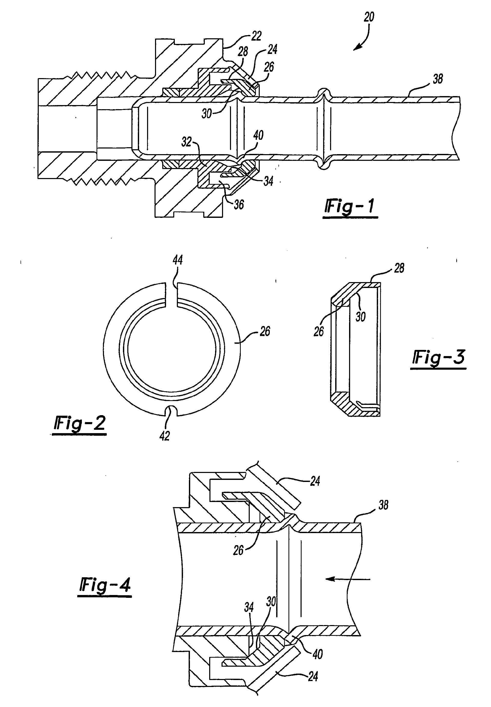
Figure 1 is a cross-sectional view through a fluid handling assembly.
Figure 2 is a front view of a collet retainer according to this invention.
Figure 3 is a cross-sectional view through Figure 2.
Figure 4 shows a feature of the collet retainer as a tube is being inserted.
DETAILED DESCRIPTION OF THE PREFERRED EMBODIMENT
[0011] A fluid handling assembly 20 is illustrated in Figure 1. As shown, a housing 22 includes
an outer structure 24 retaining a collet retainer 26. Collet retainer 26 is formed
with an axially inwardly extending leg 28. Further, an inward-facing surface of the
collet retainer 26 is formed at a ramp angle. In a preferred embodiment, this angle
is at 45 relative to a central axis of the collet retainer 26.
[0012] A pilot 32 has an inner end 34 that faces the ramp surface 30. Further, a channel
36 is formed in the pilot 32. As can be appreciated in Figure 1, the leg 28 is received
within the channel 36. The positioning of the leg 28 within the channel 36 ensures
that the collet retainer remains at least approximately centered within the housing
22 until insertion of the tube 38. As is known, the tube 38 is formed with an upset
portion 40 that moves inward of the housing 22, and past the collet retainer 26, such
that it is secured as shown in Figure 1.
[0013] Figure 2 is a front view of the collet retainer 26. As known, a collet retainer has
an expansion gap 44 between two circumferential ends. This gap allows the pilot retainer
to expand radially outwardly when the upset portion 40 engages the collet retainer
26, allowing the upset portion 40 to move into the housing 22 and beyond the collet
retainer 26. A groove 42 is formed approximately at a circumferentially opposed location
to the gap 44, and further assists this expansion.
[0014] Figure 3 is a cross-sectional view through the collet 26, and shows the ramp surface
30, and the centering leg 28.
[0015] As shown in Figure 4, as the tube 38 is being inserted, the upset portion 26 initially
contacts an outer surface of the collet retainer 26. The upset portion 44 will carry
the collet retainer inwardly until the ramp surface 30 engages end 34 of the pilot
32. At that point, the ramp surface 30 will cam along end 34, causing the collet retainer
26 to expand radially outwardly about the groove 42, and separating at gap 44 to be
circumferentially larger such that the upset portion 40 can move beyond the collet
retainer 26. At that point, the collet retainer 26 will snap back inwardly to its
relaxed position, outward of the upset portion 40 and holding the tube 38 as shown
in Figure 1.
[0016] By providing the centering structures 28 and 36, the present invention ensures the
collet retainer is properly positioned in the housing 22 prior to insertion of the
tube. Moreover, the ramp surface 30 assists this radially outward expansion.
1. A fluid handling combination assembly (20) comprising:
a housing (22); and
a collet retainer (26) adapted to be received within said housing (22), said collet
retainer (26) extending generally circumferentially around a central axis, the collet
retainer (26) having an expansion gap (44) at one circumferential location and a groove
(42) formed at an opposing circumferential location to the expansion gap (44), said
collet retainer (26) being provided with self-centering structure for ensuring said
collet retainer (26) is generally centered about a central axis of said housing (22).
2. An assembly (20) as set forth in claim 1, further comprising a tube (38) adapted to
be received by the housing (22), the tube (38) comprising an upset portion (40) for
positioning inwardly of said collet retainer (26) to hold the tube (38) within the
housing (22).
3. An assembly (20) as set forth in claim 1 or 2, wherein said collet retainer self-centering
structure includes a leg (28) arranged to extend axially inwardly and which is adapted
to be received within a channel (36) to center said collet retainer (26).
4. An assembly (20) as set forth in claim 3, wherein a distal end surface of the leg
(28) is ramped.
5. An assembly (20) as set forth in claim 3 or 4, wherein a pilot (32) is adapted to
be positioned axially inwardly of said collet retainer (26), said pilot (32) including
said channel (36).
6. An assembly (20) as set forth in claim 5, wherein the channel (36) extends between
a radially outer pilot wall and radially inner pilot wall.
7. An assembly (20) as set forth in any one of claims 2 to 6, wherein said collet retainer
(26) has a ramped surface (30), said ramped surface adapted to contact a cam surface
(34) when the tube (38) is moved to bring said collet retainer (26) axially into said
housing (22), said cam surface (34) causing said ramped surface (30) of said collet
retainer (26) to cam radially outwardly and assist radial expansion of said collet
retainer (26) as the tube (38) is moved into said housing (22).
8. An assembly (20) as set forth in claim 7, wherein the ramped surface (30) comprises
an angled inwardly facing surface.
9. An assembly (20) as set forth in claim 7 or 8, when dependent on claim 3, wherein
said leg (28) is located between said channel (36) and said ramped surface (30).
10. An apparatus (20) as set forth in any one of claims 7 to 9, when dependent on claim
3, where the ramped surface (30) is transversely angled relative to the leg (28).
11. An assembly (20) as set forth in any one of claims 7 to 10, wherein said ramped surface
(30) is angled 45 degrees relative to the central axis of the collet retainer (26).
12. An assembly (20) as set forth in any one of claims 7 to 11, when dependent on claim
5, wherein said cam surface (34) is provided on the pilot (32).
13. An assembly (20) as set forth in any preceding claim, wherein the groove (42) comprises
an axial groove.
14. An assembly (20) as set forth in any preceding claim, wherein the groove (42) is u-shaped.
15. An assembly (20) as set forth in any preceding claim, wherein the groove (42) extends
partially into said collet retainer (26) and said expansion gap (44) extends fully
through said collet retainer (26).
1. Fluidbehandlungskombinationsanordnung (20), umfassend:
ein Gehäuse (22); und
einen Klemmringhalter (26), der angepasst ist, um vom Gehäuse (22) aufgenommen zu
werden, wobei sich der Klemmringhalter (26) im Allgemeinen in Umfangrichtung um eine
zentrale Achse herum erstreckt, wobei der Klemmringhalter (26) einen Dehnungsspalt
(44) an einer Umfangsstelle aufweist und eine Nut (42), die an einer zum Dehnungsspalt
(44) entgegengesetzten Umfangsstelle gebildet ist, wobei der Klemmringhalter (26)
mit einer selbstzentrierenden Struktur versehen ist, um zu gewährleisten, dass der
Klemmringhalter (26) im Allgemeinen um eine zentrale Achse des Gehäuses (22) zentriert
ist.
2. Anordnung (20) nach Anspruch 1, ferner umfassend ein Rohr (38), das angepasst ist,
um vom Gehäuse (22) empfangen zu werden, wobei das Rohr (38) einen gestauchten Abschnitt
(40) umfasst, für eine Positionierung einwärts vom Klemmringhalter (26), um das Rohr
innerhalb des Gehäuses (22) zu halten.
3. Anordnung (20) nach Anspruch 1 oder 2, wobei die selbstzentrierende Struktur des Klemnringhalters
einen Schenkel (28) einschließt, der angeordnet ist, um sich axial nach innen zu erstrecken
und der angepasst ist, um von einem Kanal (36) aufgenommen zu werden, um den Klemmringhalter
(26) zu zentrieren.
4. Anordnung (20) nach Anspruch 3, wobei eine distale Endfläche des Schenkels (28) abgeschrägt
ist.
5. Anordnung (20) nach Anspruch 3 oder 4, wobei ein Führungsmittel (32) angepasst ist,
um axial im Inneren des Klemmringhalters (26) positioniert zu werden, wobei das Führungsmittel
(32) den Kanal (36) einsehließt.
6. Anordnung nach Anspruch 5, wobei sich der Kanal (36) zwischen einer radial äußeren
Wand des Führungsmittels und einer radial inneren Wand des Führungsmittels erstreckt.
7. Anordnung (20) nach einem der Ansprüche 2 bis 6, wobei der Klemmringhalter (26) eine
abgeschrägte Fläche (30) aufweist, wobei die abgeschrägte Fläche angepasst ist, um
eine Nockenfläche (34) zu berühren, wenn das Rohr (38) bewegt wird, um den Klemmringhalter
(26) axial in das Gehäuse (22) zu bringen, wobei die Nockenfläche (34) die abgeschrägte
Fläche (30) des Klemmringhalters (26) in eine radiale Bewegung nach außen versetzt
bringt eine radiale Rotationsbewegung nach außen hin durchzuführen und eine radiale
Dehnung des Klemmringhalters (26) zu unterstützen, wenn das Rohr (38) in das Gehäuse
(22) bewegt wird.
8. Anordnung (20) nach Anspruch 7, wobei die abgeschrägte Fläche (30) eine gewinkelte
nach innen gerichtete Fläche umfasst.
9. Anordnung (20) nach Anspruch 7 oder 8, wenn abhängig von Anspruch 3, wobei der Schenkel
(28) zwischen dem Kanal (36) und der abgeschrägten Fläche (30) positioniert ist.
10. Gerät (20) nach einem der Ansprüche 7 bis 9, wenn abhängig von Anspruch 3, wobei die
abgeschrägte Fläche (30) bezüglich des Schenkels (28) quer abgewinkelt ist.
11. Anordnung (20) nach einem der Ansprüche 7 bis 10, wobei die abgeschrägte Fläche (30)
um 45 Grad bezüglich der zentralen Achse des Klemmringhalters (26) abgewinkelt ist.
12. Anordnung (20) nach einem der Ansprüche 7 bis 11, wenn abhängig von Anspruch 5, wobei
die Nockenfläche (34) auf dem Führungsmittel (32) bereitgestellt ist.
13. Anordnung (20) nach einem der vorhergehenden Ansprüche, wobei die Nut (42) eine axiale
Nut umfasst.
14. Anordnung (20) nach einem der vorhergehenden Ansprüche, wobei die Nut (42) U-förmig
ist.
15. Anordnung (20) nach einem der vorhergehenden Ansprüche, wobei sich die Nut (42) teilweise
in den Klemnwinghalter (26) erstreckt und sich der Dehnungsspalt (44) vollständig
durch den Klemmringhalter (26) hindurch erstreckt.
1. Ensemble combiné pour le traitement de fluides (20), comprenant :
un boîtier (22) ; et
une bague de retenue (26) adaptée pour être reçue dans ledit boîtier (22), ladite
bague de retenue (26) s'étendant généralement de manière circulaire autour d'un axe
central, la bague de retenue (26) comportant un jeu de dilatation (44) au niveau d'un
emplacement circulaire et une rainure (42) formée au niveau d'un emplacement circulaire
opposé au jeu de dilatation (44) ladite bague de retenue (26) étant munie d'une structure
d'auto-centrage pour s'assurer que ladite bague de retenue (26) soit généralement
centrée sur un axe central dudit boîtier (22).
2. Ensemble (20) selon la revendication 1, comprenant en outre un tube (38) adapté pour
être reçu dans le boîtier (22), le tube (38) comprenant une partie montante (40) pour
un positionnement vers l'intérieur de ladite bague de retenue (26) pour tenir le tube
(38) dans le boîtier (22).
3. Ensemble (20) selon la revendication 1 ou 2, dans lequel ladite structure d'auto-centrage
de bague de retenue inclut une patte (28) arrangée pour s'étendre axialement vers
l'intérieur et qui est adaptée pour être reçue dans un canal (36) pour centrer ladite
bague de retenue (26).
4. Ensemble (20) selon la revendication 3, dans lequel une surface d'extrémité distale
de la patte (28) est chanfreinée.
5. Ensemble (20) selon la revendication 3 ou 4, dans lequel un guide (32) est adapté
pour être positionné axialement vers l'intérieur de ladite bague de retenue (26),
ledit guide (32) incluant ledit canal (36).
6. Ensemble (20) selon la revendication 5, dans lequel le canal (36) s'étend entre une
paroi du guide radialement extérieure et une paroi du guide radialement intérieure.
7. Ensemble (20) selon l'une quelconque des revendications 2 à 6, dans lequel ladite
bague de retenue (26) comporte une surface chanfreinée (30), ladite surface chanfreinée
étant adaptée pour contacter une surface de came (34) quand le tube (38) est déplacé
pour introduire ladite bague de retenue (26) axialement dans ledit boîtier (22), ladite
surface de came (34) imprimant un mouvement radial vers l'extérieur à la surface chanfreinée
(30) de ladite bague de retenue (26) et assistant l'expansion radiale de ladite bague
de retenue (26) quand le tube (38) est déplacé dans ledit boîtier (22).
8. Ensemble (20) selon la revendication 7, dans lequel la surface chanfreinée (30) comprend
une surface inclinée tournée vers l'intérieur.
9. Ensemble (20) selon la revendication 7 ou 8, lorsque dépendant de la revendication
3, dans lequel ladite patte (28) est située entre ledit canal (36) et ladite surface
inclinée (30).
10. Appareil (20) selon l'une quelconque des revendications 7 à 9, quand dépendant de
la revendication 3, dans lequel la surface chanfreinée (30) est inclinée transversalement
par rapport à la patte (28).
11. Ensemble (20) selon l'une quelconque des revendications 7 à 10, dans lequel ladite
surface chanfreinée (30) est inclinée à 45 degrés par rapport à l'axe central de la
bague de retenue (26).
12. Ensemble (20) selon l'une quelconque des revendications 7 à 11, quand dépendant de
la revendication 5, dans lequel la surface de came (34) est fournie sur le guide (32).
13. Ensemble (20) selon l'une quelconque des revendications précédentes, dans lequel la
rainure (42) comprend une rainure axiale.
14. Ensemble (20) selon l'une quelconque des revendications précédentes, dans lequel la
rainure (42) est en forme de U.
15. Ensemble (20) selon l'une quelconque des revendications précédentes, dans lequel la
rainure (42) s'étend partiellement dans ladite bague de retenue (26) et ledit jeu
de dilatation (44) s'étend entièrement à travers ladite bague de retenue (26).
REFERENCES CITED IN THE DESCRIPTION
This list of references cited by the applicant is for the reader's convenience only.
It does not form part of the European patent document. Even though great care has
been taken in compiling the references, errors or omissions cannot be excluded and
the EPO disclaims all liability in this regard.
Patent documents cited in the description