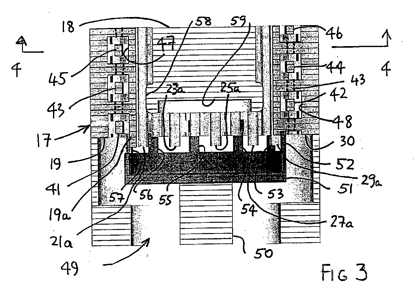
(57) A magnetron has a first set of vanes 30 etc which connect by legs 52 to a coaxial
output coupler 51 and a second set of vanes 19 etc which (in one embodiment) alternate
with the vanes of the first set and are not connected to the output coupler. The vanes
of each set are held, for example, by strap rings which may be distributed along the
length of the anode, at the same potential as each other, and the polarity of the
vanes of one set is opposite to that of the other set. A problem with such a magnetron
is that there is capacitive coupling between the cathode and the output coupler 51,
which can lead to the coaxial TEM mode propagating along the cathode. According to
the invention, additional capacitive coupling is introduced by means of axial extensions
19a etc on the ends of the set of vanes 19 etc which are not connected to the output
coupler, and by choice of dimensions, the cathode is substantially decoupled from
the output coupler because of the opposite polarity of the two sets of vanes.
|
|
